Geometric dimensioning and tolerancing
Geometric dimensioning and tolerancing defines allowable variations in form, orientation, profile, and runout of geometrical features in engineering design. 14 standard GD&T symbols (12 in Y14.5-2018 )are used with feature control frames, which convey consistent information about feature control among designers, engineers, and procurement teams.
GD&T uses theoretically exact dimensions to define theoretically exact locations, orientations, and profiles. Meanwhile, datum reference frames in GD&T provide a reference system used to locate and orient related features. However, you need to call out them correctly.
This article will discuss 14 GD& symbols, modifiers, feature control frames, ASME Y14.5 and ISO 1101 standards, and quality inspection with simulated datums.
What is GD&T and Why ±Tolerancing Fails on Complex Parts?
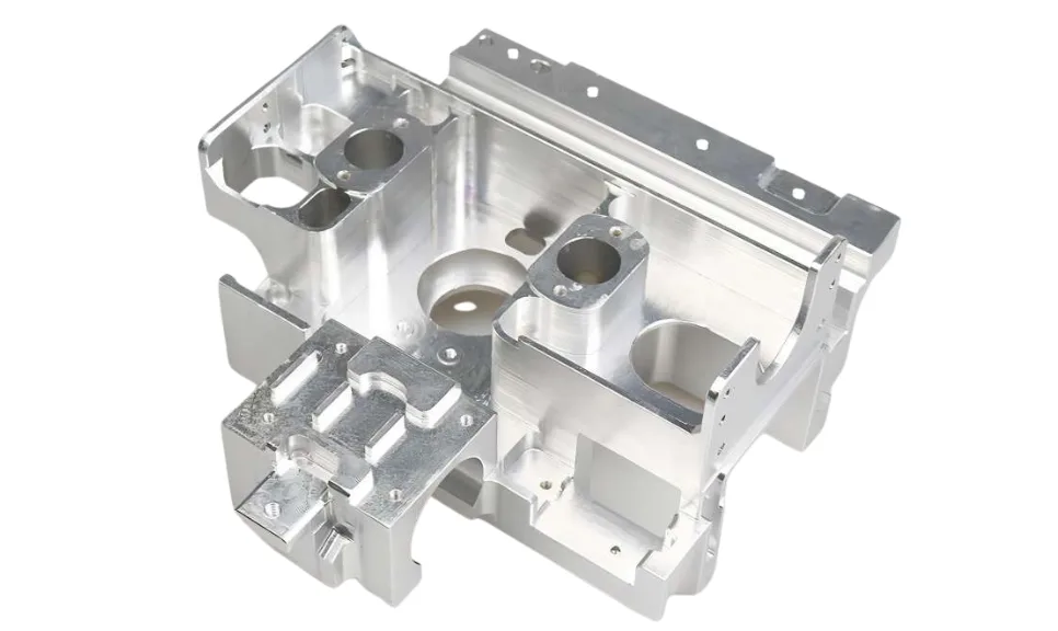
Complex CNC-machined part
Geometric Dimensioning and Tolerancing (GD&T) is an engineering language in mechanical designs. It uses standard symbols to define and communicate allowable variations in the forms, positions, orientations, profiles, and runout of geometric features. Designers use data, dimensions, and feature control frames in drawing, providing a universal understanding of the designed part or system.
The American Society of Mechanical Engineers (ASME) and the International Organization for Standardization (ISO) are two major governing bodies for GD&T. They define 14 main symbols of geometric characteristics, a datum framework, bonus tolerance, and interpretation rules.
Why ±Tolerancing Fails on Complex Parts?
Plus/minus (±) tolerancing fails on complex parts because it only controls deviations in dimensions, not the geometrical, positional, and functional characteristics of features. So, it can increase the tolerance stack-up and impact the assembly fit, alignment, and functionality of the manufactured part.
Absence of a feature control frame makes inspection and verifications of precision challenging because without standard GD&T, CMM, and other machines can not read feature-to-feature position, orientation, and other parameters.
The 14 Symbols, Grouped by What They Control: GD&T Symbols Chart
| GD&T Category | Name | Symbol | Tolerance Zone | What Does It Control? |
| Form | Flatness | ⏥ | Two parallel planes separated by the tolerance value | Deviation from the surface’s true flatness |
| Straightness | ⏤ | Two parallel lines/cylinders | Straightness of surface or line | |
| Circularity | ○ | Two concentric circles | Roundness at any single cross-section | |
| Cylindricity | ⌭ | Two coaxial cylinders | Roundness, taper, and straightness of the feature | |
| Orientation | Perpendicularity | ⟂ | Two parallel planes/ Cylinder at 90° to a datum | Perpendicularity of surface or line with datum axis |
| Angularity | ∠ | Two parallel planes | Any specified angle other than 90° | |
| Parallelism | ∥ | Two parallel planes/cylinder/ a cylinder | How parallel a surface or axis is to a datum | |
| Location | Position | ⌖ | Cylinder or two planes centered on the true position | Position of holes, slots, tabs, and other features with respect to datums |
| Concentricity | ◎ | Cylinder about a datum axis | Derived median points of a feature relative to a datum axis | |
| Symmetry | ⌯ | Two parallel planes about a datum center plane | Even distribution of a feature about a datum center plane | |
| Profile | Line profile | ⌒ | Two offset boundaries from the true line profile | 2D contour at each cross-section |
| Profile of a Surface | ⌓ | 3D boundary offset from the true shape | Form, orientation, location, and sometimes size of a surface | |
| Runout | Circular Runout | ↗ | Two concentric circles in each cross-section | Wobble and eccentricity of 2D cross-section |
| Total Runout | ⌰ | Two coaxial cylinders | Entire 3D surface |
There are 14 commonly used GD&T symbols. They are divided into 5 categories: form, orientation, location, runout, and profiles based on what geometrical features and characteristics they control.
Form Tolerances
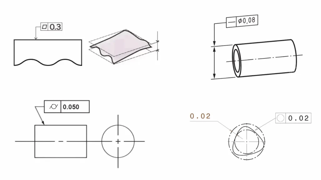
Form tolerances
Form tolerances (flatness, straightness, circularity, and cylindricity) control the shape accuracy of individual geometric features. For instance, flatness-tolerance controls allowable deviations of planner surfaces from the perfectly flat plane. When the design is passed to the production team, A manufacturing engineer and machinist understand by looking at its GD&T callout.
No datum
- Flatness: It controls the deviations of the planner surface with respect to a perfect plane within a tolerance zone defined by two parallel lines. A small parallelogram (⏥) is its symbol, and tolerance values are also placed alongside the symbol.
- Straightness: It defines the allowable deviation (curve, bend, or warp) of individual line elements or axes from a perfectly straight line. The straightness GD&T symbol is a straight dash (⏤).
- Circularity: Circularity is also known as roundness; it controls how close a circular cross-section is to a perfectly circular geometry. The GD&T symbol of circularity is a small circle(○).
- Cylindricity: Cylindricity (⌭) defines the shape of a cylindrical feature as how close it is to a perfect geometric cylinder. It controls the cylindrical feature within a zone between two coaxial cylinders.
Orientation Tolerances
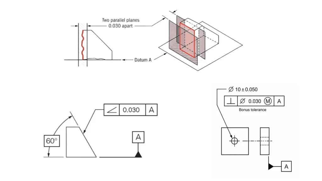
Orientation tolerances GD&T
Unlike form tolerances, orientations are the datum-referenced geometric dimensioning and tolerancing symbols, and they define the orientation of any particular feature with respect to a referenced line, axis, or surface. There are three different orientation tolerances in GD&T: Perpendicularity, Angularity, and Parallelism.
- Perpendicularity: It controls that an axis or surface is at a perfect 90° to the defined datum reference or within the allowable range. For instance, a 200 mm bearing enclosure face should be at 90° to the bore axis(A). A callout symbol ⊥ 0.05 A means the face should lie between two planes 0.05 mm apart and at 90° to the bore axis.
- Angularity: Angularity controls the angular accuracy of axes, surfaces, or planes (except 0 & 90°) with respect to the reference datum. Its GD&T symbol is an acute angle opened on the right side (∠).
- Parallelism: It controls how close any axis, surface, or plane is to 0° alignment with the datum. The parallelism symbol is two parallel lines with a small spacing (∥). For instance, ∥ 0.04 |B.
Location Tolerances
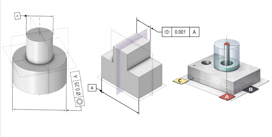
GD&T of location tolerances
Location tolerances define the allowable deviations of features from their true locations (theoretical) mentioned in the design. Three types of location tolerance are position, concentricity, and symmetry.
- Position: It defines the permissible positional deviation of features such as a bore, hole, slot, or channel from the exact theoretical positions. Locations are controlled through the coordinates of Datum references. Meanwhile, its GD&T symbol is ⌖.
- Concentricity: Concentricity defines the axial deviation of a single feature or multiple features that must be concentric with the referenced datum axis. The GD&T symbol of concentricity is two small concentric circles (◎).
- Symmetry: Symmetry ensures a feature is symmetrical to the datum plane. It defines the permissible distance from a feature to two parallel planes on both sides of the center of the datum plane. The GD&T symbol for symmetry is two parallel lines placed at equidistant from a datum line (⌯).
Profile Tolerances
Profile tolerances control how closely line or surface profiles match the form, location, orientation, and size of their true theoretical profiles. Its GD&T symbol is ⌓, and is extensively used for curved and freeform geometries.
- Line Profile: Used for 2D cross-sections, such as curved edges.
- Surface Profile: Used for 3D profiles and controls the entire surface area of the feature.
Runout Tolerances
Runout tolerances ( Circular and total) define the permissible deviation of a rotating surface with respect to a datum axis around which the part rotates. They are useful for controlling oscillations and surface variations in rotating components. (Read how runout tolerances differ from machining runout)
- Circular Runout: It controls surface variations at each individual circular cross-section, and a single arrow (↗) is used as a GD&T symbol.
- Total Runout: Total runout tolerance controls the full length and circumference of the part when the part rotates around its datum axis. Its GD&T symbol is two parallel arrows (↗↗).
How to Read a Feature Control Frame?
The feature control frame is an annotation in an engineering drawing that contains a GD&T symbol and all related tolerancing information, including the tolerance zone, datums, and the intent of the tolerance. For instance, ∥ 0.04 | A is read as the callout surface must be parallel to datum A with a deviation limit of 0.4mm.
Step-wise Guide with an Example
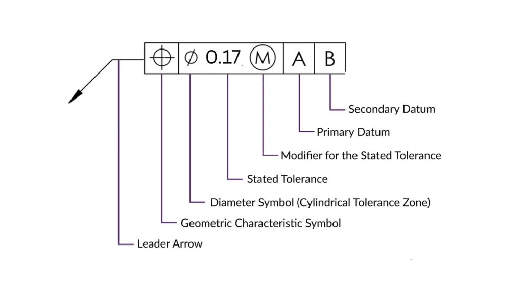
Feature control frame
Identify the Callout Feature
Which surface, line, hole, or other feature does GD&T direct? You can look at the leader arrow extended from the GD&T annotations.
Read GD&T Symbol
Read the GD&T symbol in the first compartment of the feature control box, which defines which geometric characteristic is being controlled. For instance, the example above has a position symbol ⌖.
Identify the Tolerance Zone
In the next compartment after the symbol, you get the tolerance zone and value. You can read ⌀ 0.17 Ⓜ in the above example, where ⌀ suggests a cylindrical tolerance zone with 0.17 mm permissible deviation, and the Ⓜ symbol indicates the MMC modifier.
Datum References
After the MMC modifiers, identify the datum references for tolerancing. There can be more than one datum: primary, secondary, and tertiary. In the example above, you can see two datums, A and B, defining the locating references.
What is Tolerance Stacking?
Tolerance stacking is a cumulative effect of geometric and dimensional variations caused by multiple features in a part. In assembly, geometric and dimensional variations in parts and their features contribute to the tolerance stackup. It is used in manufacturing to evaluate whether parts as a whole are within the tolerance limit or not.
Example of Tolerance Stacking
Let’s take an example of a brake disc and a caliper with four different features: caliper mount surface, knuckle mount surface, hub-to-knuckle position, brake-disc mount surface with tolerances 110 ±0.20 mm, 20 ±0.10 mm, 5 ±0.10 mm,10 ±0.10 mm. The tolerance stacking in this case is ±0.50 mm.
Datum Reference Frames and the 6 Degrees of Freedom
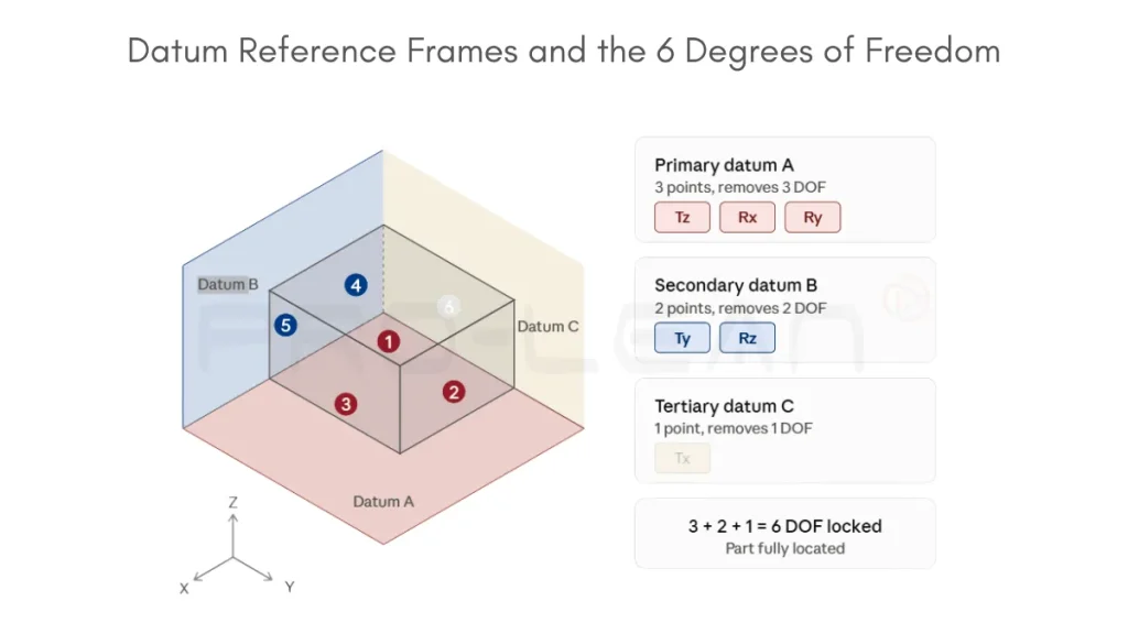
DOF and Datums
A datum reference is defined as the true theoretical plane, axis, or point of a feature in the engineering design. Datum reference frames provide fixed coordinate systems to constrain and track the pat’s six degrees of freedom.
Primary, secondary, and tertiary Datums
After establishing a datum reference frame, you can define the relative position, orientation, profile, and runout of geometrical features. It means each added datum reference locks one or more degrees of freedom. (Read more about datums in GD&T Datum Explained)
3-2-1 rule for datum reference frames and degrees of freedom is as follows;
- Primary (A) datum locks 3 DOF and establishes the first planar surface
- Primary (B) datum locks 2 DOF (X and Z) and establishes the second perpendicular plane.
- Tertiary (C) datum locks 1 DOF and establishes a third perpendicular.
Combined, the three datums lock all six degrees of freedom and provide a reference mathematical coordinate system for measuring and controlling GD&T characteristics. So,
Datum Targets on Cast and Forged Surfaces
In cast and forged parts, the surface texture is not smooth, and they contain high spots, draft transitions, warpages, flashes, and parting lines. So, datum establishment is critical for the precision of parts and features on them.
Datums are targeted in points, lines, and areas of cast and forged surfaces. Datum point targets points on rough castings and forging surfaces, datum lines target edges or ribs, and datum area targets particular faces of casting parts.
Simulated Datums in Inspection
Simulated datums are practical references in the physical part and serve as true geometrical counterparts, as defined in the GD&T of any engineering drawings. They are different from machining datums, and machines & instruments generate simulated datums based on measuring the points, angles, profiles, and other important data.
Machines and instruments that establish the simulated datums are called datum feature simulators, such as CMM machines and digital gauges.
Material Condition Modifiers: MMC, LMC, RFS, and Bonus Tolerance
Material condition modifiers are used in GD&T to control the allowable changes to geometric tolerances when a feature size changes. They are important for ensuring that the features remain within tolerance limits when material conditions change. Maximum material condition and Least material conditions (MMC and LMC), and regardless of feature size (RFS), are three material condition modifiers.
Maximum Material Condition (MMC )
MMC is a condition of a feature of size corresponding to the maximum amount of material, while remaining within the limits of position, orientation, profile, and runout tolerances. For instance, MMC in shaft and hole design means the geometric tolerances remain unchanged even for the largest shaft and smallest hole, maintaining the desired fit.
The MMC modifier adds bonus tolerances geometric tolerances when the size of the actual feature lowers from the MMC to the, providing flexibility in manufacturing.
Example:
For a 60 mm diameter shaft with 0. 60 mm tolerance (Ø60.00 ± 0.60 mm), the maximum material condition is 60+0.60 =Ø60.60 mm. It means the geometric tolerances are applicable up to Ø60.60 mm.
Least Material Conditions (LMC)
LMC is a condition of the lowest material condition, where geometric tolerances are within its specified size limits. If the LMC symbol is placed after the geometric tolerance value in GD&T, the tolerance is limited to the lowest material conditions and earns a bonus tolerance when the size moves towards MMC.
Example:
For a shaft Ø60.00 ± 0.60 mm, the permissible size range is Ø59.40 to 60.60 mm, and the bonus tolerances are added when the size increases from the lowest material condition (Ø59.40) towards MMC.
Regardless of Feature Size (RFS)
If maximum or least material modifier symbols( Ⓜ or Ⓛ) are not included in the GD&T feature control frame, it means the size of the part and geometric tolerances are independent of each other.
Bonus Tolerance
If the material conditions deviate from MMC or LMC and lie within the specified size limit, a bonus tolerance is added to the geometric tolerances. This provides more flexibility in manufacturing, especially for fit & assembly.
It means that when a designer specifies MMC or LMC, the geometric tolerances are designed for the worst-case scenario of feature sizes. As the actual size moves away from the specified material condition, the geometric tolerances increase.
Example:
Let’s consider you machine shaft with Ø60.40 mm, whose specified size was Ø60.00 ± 0.60 mm and positional tolerance was ⌖ ⌀0.20 Ⓜ | A | B.
MMC= Ø60.60
Actual Size= Ø60.40 mm
Deviation from Specified MMC (bonus tolerance)= Ø60.60-Ø60.40 = Ø0.20
Total positional tolerance= ⌀ 0.20+ ⌀ 0.20=⌀0.40 mm
ASME Y14.5 vs ISO 1101: What Actually Differs?
ASME Y14.5 and ISO 1101 are the international standards used to define Geometric dimensioning and tolerancing (GD&T) requirements in engineering drawing. ASME Y14.5 is governed by the American Society of Mechanical Engineers, and the International Organization for Standardization governs ISO 1101. ASME is widely used for the Maximum Material Condition (MMC), whereas size and geometric tolerances are independent in ISO 1101.
ASME uses RSF as the default material condition, and Ⓜ Ⓛ is applied explicitly. On the other hand, ISO 1101 specifies MMR/LMR requirements as defined in ISO 2692.
Symbols that were removed: Since the 2018 ASME Y14.5 edition, the symmetry and concentricity symbols have been removed, but you can control median-point requirements, position, profile, or runout.
What Each Symbol Costs to Hold?
Including more GD&T symbols means defining several geometric tolerances, which makes process planning relatively complex and increases quality inspection & verification costs. Additionally, the machining process route varies with the desired level of accuracy.
IT Grades
IT Grades, or international tolerance grades, are sets of standards that define permissible variations in tolerances and linear dimensions in manufacturing, based on applications and process routes. From IT01 to IT18, 18 IT tolerance grades are defined under ISO 286.
Using IT grades allows specifying the tolerance achievable with machining. So, they are typically encountered with ISO fits and tolerance designations. For instance, the H7/h6 IT grades define the width of the tolerance zone, and you can use H7/h6 charts for reference.
| Approx. IT grade | Typical achievable process route* | Typical engineering application | What starts driving cost |
| IT12–IT13 | Sawing, rough machining, general fabrication, rough turning/milling | Non-critical dimensions, stock preparation, clearance features | Basic process control |
| IT10–IT11 | General CNC turning/milling, drilling, standard boring | General machined dimensions, non-critical interfaces | Stable tooling and routine inspection |
| IT8–IT9 | Controlled CNC turning/milling, precision boring, reaming | Functional holes, shafts, locating features, moderate fits | Better tool control, offsets and SPC |
| IT7–IT8 | Precision CNC machining, finish boring, reaming, controlled turning | Precision fits, bearing-related features, accurate locating surfaces | Higher process capability and tighter environmental/process control |
| IT6–IT7 | Precision turning, grinding, precision boring, honing depending on feature | Bearing seats, precision journals, high-accuracy fits | Secondary finishing and tighter inspection |
| IT5 and finer | Grinding, honing, lapping, superfinishing or specialized precision processes | High-precision interfaces and metrology-critical features | Specialized equipment, environmental control and extensive inspection |
*These are indicative engineering ranges, not guaranteed process capabilities. The same nominal IT grade can have very different manufacturing difficulty depending on part size and geometry.
Where Over-callout Quietly Doubles Your Price?
Over-callout of GD&T in your engineering drawing increases or doubles the machining price, because including several layers of tight tolerances demands higher process capability, strict quality control, and rigorous quality measurements & verification.
Here are the conditions where over-tolerancing can double the machining cost;
- When you set the tight dimensional tolerances on features that are non-critical
- When you call out tight positional tolerances on holes, curvatures, and other features.
- When tight flatness is required on non-sealing surfaces.
- When you define surface finish requirements (low Ra), even though they are not required for functionality.
- When multiple datum transfers are required to verify the tolerances.
Writing GD&T Callouts Your Supplier Can Quote From
The main of geometric dimensioning and tolerancing is to convey the information about the characteristics of a part’s features between designers, procurement teams, factory engineers, quality control engineers, and all stakeholders. When you clearly specify the GD&T symbols and values while sending the design to your supplier for quotation, you get an accurate estimation and practical DFM feedback.
We recommend writing the following GD&T callouts in your designs to get a quote within 24 hours.
- First, define the critical-to-quality (CTQ) features and callout tolerances required for functionality
- Define the correct datum reference frame (DRF)
- Specify LMC or MMC material conditions
- Avoid unnecessary tolerance stack-up
We not only quote your design, but also offer the best online CNC services tailored to your manufacturing needs. You can leverage our multi-axis CNC equipment and professional experts to machine your parts and prototypes precisely.
FAQs
What are the 14 GD&T symbols?
The 14 GD&T symbols are straightness, flatness, circularity, cylindricity, position, concentricity, symmetry, profile of a line, profile of a surface, circular runout, and total runout. These are categorized into five types: form, orientation, location, profile, and runout. Furthermore, ASME Y14.5-2018 has removed symmetry and concentricity symbols, and there are only 12 active symbols under ASME.
ASME Y14.5 vs ISO 1101 — which should I use?
The geometric and dimensional tolerancing symbols are almost identical. Choose them based on your region, customer specifications, and your firm’s practices.
What does MMC mean?
MMC is the maximum material condition for a feature where its geometric tolerances are unchanged while being within the size limit. When the feature in the actual part moves away from MMC, it provides bonus tolerance, increasing manufacturing flexibility and reducing cost.
How do I read a feature control frame?
To read a feature control frame, go through each compartment from left to right.
- First compartment → Read Geometric Symbol, which type of tolerance is being controlled.
- Second Compartment → Read tolerance zone and material modifiers Ⓜ / Ⓛ( zone type and value, E.g., ⌀ 0.20 for cylindrical zones).
- Next Compartments: Read primary secondary tertiary datums in their order of precedence.