
RIGID STRUCTURE. FUNCTIONAL SURFACE.
Overmolding
Services
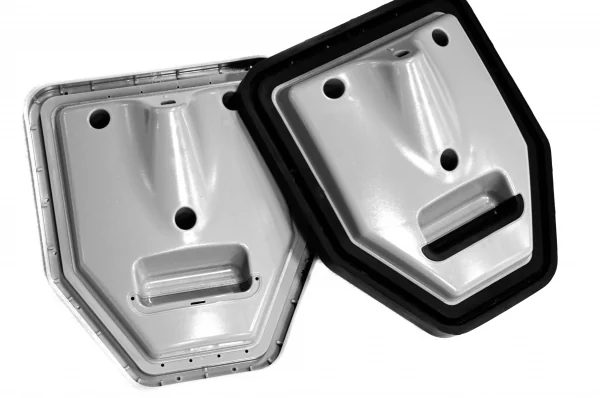
Add grip, sealing, insulation or vibration control to your component. Review the material pair, interface and tooling with ProleanTech.
Start with what the
outer layer needs to do.
Overmolding adds a material to a preformed substrate. A rigid core can carry the load while a softer layer provides the contact surface. Select the function below to identify the requirements that belong in your RFQ.
A secure hold starts with the interface.
Handles, controls and hand-contact surfaces combine a rigid structure with a softer outer layer. Define the contact area, grip texture, target hardness and exposure to sweat, oils or cleaning agents.
- Peel resistance at exposed edges
- Wet or dry grip in the intended use
- Wear, color and tactile consistency
Contact area, target hardness, cleaning agents and expected handling cycles
Design the seal around the assembled condition.
An integrated sealing bead must work against its mating surface. Provide the assembled gap, compression range, mating-part geometry and exposure conditions. Bond strength and leak performance need separate acceptance criteria.
- Compression and recovery over the service life
- Flash and parting lines away from the sealing path
- Leak test conditions for the complete assembly
Mating CAD, compression range, fluid, temperature and leak-test method
Define the electrical requirement beyond material choice.
A molded insulating layer needs controlled coverage and protected contact areas. Specify working conditions, minimum functional wall requirements and the applicable electrical or flammability specification.
- Coverage, voids and exposed conductive areas
- Dielectric or insulation-resistance testing if required
- Grade-specific documentation and assembly clearances
Electrical specification, keep-out areas, layer geometry and required documents
Match damping to the load and frequency.
A compliant layer can change how a housing or mount transmits vibration. Define the loaded geometry, frequency range, temperature and allowable movement so the design can be assessed in its actual assembly.
- Dynamic response at the working load
- Creep, compression set and aging
- Retention under repeated motion
Mass, load, frequency range, service temperature and functional test
Have several functions in one part? Share the assembly and service conditions. Grip, adhesion and sealing may need different tests.
Choose the molding route.
Then define the tool.
Overmolding, insert molding and two-shot molding are related terms, but they do not specify the same production setup. Confirm the proposed route against your geometry, material pair, design stability and repeat demand.
Overmolding
A second material is molded onto selected areas of a substrate. Retention can come from grade-specific adhesion, mechanical features or both.
The decisionWhich layer adds the required function, and where must it remain attached?
Insert molding
A preformed plastic, metal or other component is located in the mold before injection. This can be the production method for an overmolded part.
The decisionHow is the insert located, supported, protected and checked before loading?
Two-shot molding
Two materials are molded in a coordinated cycle using dedicated tooling and equipment. It can reduce separate handling when the project justifies the setup.
The decisionDoes the forecast quantity and stable design justify the added tooling complexity?
Specify your required process in the RFQ. The quotation confirms process availability and the production route for your part.
MATERIALS WORK AS A PAIR
Match exact grades.
Then validate the bond.
“TPE on plastic” is not a complete material specification. Substrate resin, overmold formulation, additives, surface condition and processing history affect adhesion. Use the pairings below to frame a selection discussion; agree the exact grades and trials before tooling release.
| Substrate | Overmold selection | Function to discuss | Engineering review |
|---|---|---|---|
| PP | PP-bonding TPE grade | Grip surfaces and compliant features | Confirm the grade is formulated for PP adhesion; review peel loading, shrinkage and service temperature. |
| ABS / PC / PC-ABS | TPE or TPU grade selected for the exact substrate | Controls, grips and protective interfaces | Review resin compatibility, substrate heat response and stress sensitivity; identify additives and mold-release history. |
| PA / glass-filled PA | PA-compatible overmolding grade | Structural parts with a softer contact zone | Specify PA type, reinforcement and conditioning. Moisture, surface state and dimensional change affect the interface. |
| POM / PE / other low-adhesion substrates | Specialized adhesion grade or engineered retention | Parts requiring a deliberate bonding strategy | Do not assume a general-purpose elastomer will bond. Review supplier data, interlocks and representative trials. |
| Metal or other preformed insert | Application-specific polymer and retention design | Encapsulation, insulation or localized compliance | Define alloy, coating, cleanliness and heat sensitivity. Mechanical capture and any primer or surface treatment require review. |
Hardness is one input.
Specify the hardness scale and target along with abrasion, tear strength, friction, chemical exposure, temperature and aging requirements. A softer grade does not automatically provide better grip, sealing or damping.
Silicone needs its own process review.
Liquid silicone rubber uses a different curing process from thermoplastic elastomers. Confirm substrate heat resistance, bonding strategy and process availability separately if silicone is required.
The interface is a
feature to engineer.
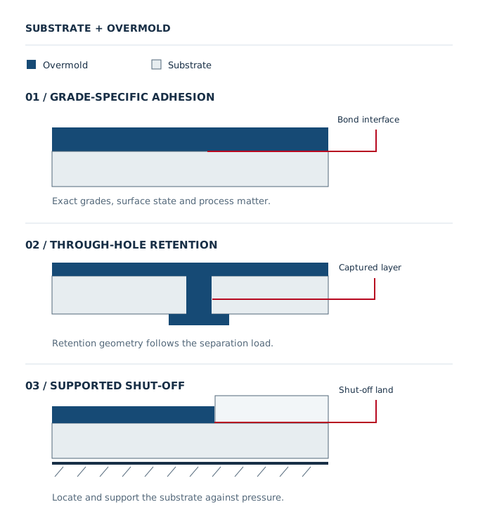
Review how the layer is retained, how the mold seals against the substrate and how both materials move as they cool. A clean boundary on the model needs a practical shut-off, support and molding sequence.
Adhesion & mechanical retention
Use supplier guidance for the exact grade pair. Through-holes, grooves or captured edges can help resist separation when designed for the load direction. Mechanical capture does not by itself create a fluid-tight bond.
Shut-offs & parting lines
Provide a defined land where the mold closes against the substrate to stop material flow. Support the substrate against injection pressure, and keep flash, parting lines and witness marks away from sealing paths and hand-contact edges.
Wall transitions & flow
Keep the overmold layer consistent where practical. Review abrupt thickness changes, long thin flow paths, venting and gate locations to manage incomplete fill, trapped air, sink and visible flow marks.
Shrinkage, location & distortion
Review differential shrinkage between the materials, substrate stiffness and the support scheme. Identify functional datums and the dimensions that apply after overmolding; allow for insert variation in the locating scheme.
Surface state & handling
Specify drying and conditioning requirements, surface treatments and permitted release agents. Keep bond areas free of contamination. Agree storage, handling and traceability when substrates come from a separate supply step.
Mark the boundary on your model. Add keep-out zones, exposed edges, cosmetic faces and areas where the mold can contact the substrate.
FINISHED-PART ACCEPTANCE
Specify appearance.
Verify the function.
Define the acceptance plan before sample approval. A dimensionally correct part still needs the bond, seal, feel or electrical performance required by its application.
Test the bond for the way
the part will be loaded.
Agree a peel, pull or other retention test suited to the geometry. Define fixture, loading direction, conditioning, failure mode and acceptance limit. Repeat the relevant checks after exposure or aging when the application requires it.
Representative molded trials are more useful than assuming compatibility from resin family names alone.
- Dimensions & assembly fit
- Critical substrate locations, overmold coverage, thickness, distortion and fit to mating components. State measurement datums, conditioning and sampling.
- Appearance & touch
- Color, texture, gloss, visible flow lines, gate marks, flash limits and exposed boundaries. Use agreed cosmetic zones and approved samples.
- Application performance
- Leak, compression, insulation, wear or vibration tests as applicable. Define the assembled condition, exposure and test method.
- Order documentation
- Agree first-article results, dimensional reports, material records and lot traceability required for your order.
Material properties and component tests do not establish a finished product’s regulatory approval or ingress rating. Include any application-specific qualification requirements at the inquiry stage.
Plan the tooling around
the complete supply route.
Review the substrate and overmold as one assembly, including who makes the first component, how it is loaded and how the finished part is approved. Separate tooling investment from repeat-part cost when comparing quotations.
Cavities, loading access, locating features, gates, shut-offs, side actions, ejection and substrate support.
Substrate supply, tooling ownership, maintenance, expected production demand, packaging and delivery destination.
Approved CAD revision, material substitutions, tool changes and revalidation after design or process changes.
Agree the approval path before the batch.
- 01Review files
Resolve material pairing, interfaces, quantity and open requirements.
- 02Confirm scope
Agree tooling, route, quotation, schedule and the controlled revision.
- 03Approve samples
Check appearance, dimensions and the agreed functional tests.
- 04Release production
Use the approved specification, inspection plan and delivery documents.
Practical order quantity and lead time depend on the part, material sourcing, tooling, trials and approval requirements. Include initial quantity, repeat forecast and your required date.
Overmolding
questions, answered.
Material pairing, process selection and the information that makes an inquiry useful.
What is overmolding?
Overmolding forms an additional material over part of an existing substrate. The substrate provides structure or an interface; the overmold adds a grip, sealing feature, insulation or a compliant layer. The design must address material compatibility, retention, molding conditions and the finished assembly’s requirements.
What is the difference between overmolding, insert molding and two-shot molding?
Overmolding describes adding a molded layer to a substrate. Insert molding describes placing a preformed component in a mold before injecting material around it; it can be used to make an overmolded part. Two-shot molding forms two materials in a coordinated molding cycle. These terms describe different aspects of the process, and the route is confirmed for your project.
Will TPE or TPU bond to my plastic substrate?
Bonding depends on the exact grades of both materials, the surface condition and the molding process. TPE and TPU are material families, not universal bonding specifications. Send both grade references and application conditions. Supplier compatibility guidance and representative trials should support the selected pair; mechanical retention may also be needed.
Can an overmolded seal make my product waterproof?
A sealing layer alone does not establish an ingress rating. The complete assembly, compression, mating surface, parting lines, material aging and test conditions determine performance. State the required rating or leak-test specification and provide the mating geometry so the sealing path can be reviewed.
Can you overmold a customer-supplied component?
Include the component CAD, drawing, exact material, surface treatments and quantity in your inquiry. Component location, handling, incoming dimensional variation, heat resistance and responsibility for rejected inserts need agreement before a supply route is accepted. Send details before shipping any components.
Do you offer two-shot or silicone overmolding?
Specify two-shot molding or silicone explicitly if your design requires it. These routes have different tooling, processing and substrate constraints from thermoplastic overmolding. ProleanTech confirms process availability, material pairing and the production route in the project quotation; do not substitute one route for another without engineering approval.
What determines tooling cost, order quantity and lead time?
Part geometry, substrate sourcing, cavity count, insert loading, retention features, side actions, material selection, trials and inspection scope all affect the quotation. Include initial and repeat quantities, design maturity and the required delivery date. Tooling development, sample approval and repeat-production timing should be agreed separately.
What should I send for an overmolding quote?
Send separate substrate and overmold CAD bodies, an assembly model and a controlled 2D drawing with units and revision. Add exact material grades or target properties, overmold boundaries, hardness, color, texture, critical dimensions, quantity breaks and destination. Include bonding, sealing, electrical or vibration tests and required documentation where applicable.
YOUR NEXT OVERMOLDED PART
Bring the assembly.
Define the interface.
Send your part files and operating requirements. We’ll review the substrate, outer layer, tooling and acceptance criteria with your quotation.
Your files stay confidential. Optional NDA available ↗
Your overmolding RFQ checklist
- Part definitionSeparate substrate and overmold bodies, assembly CAD, 2D drawing, units and revision.
- Material pairExact grades or target properties, hardness scale, color, texture and service conditions.
- Interfaces & acceptanceBoundaries, keep-outs, datums, mating parts, bond requirements and functional tests.
- Order & tooling scopeQuantity breaks, repeat forecast, substrate supplier, tool ownership, date and destination.