
METAL & PLASTIC PART MANUFACTURING
Rapid Prototyping
Services
ProleanTech provides metal and plastic prototypes for form, fit and functional evaluation. Send your design for a review of the process, material, finishing and inspection requirements.
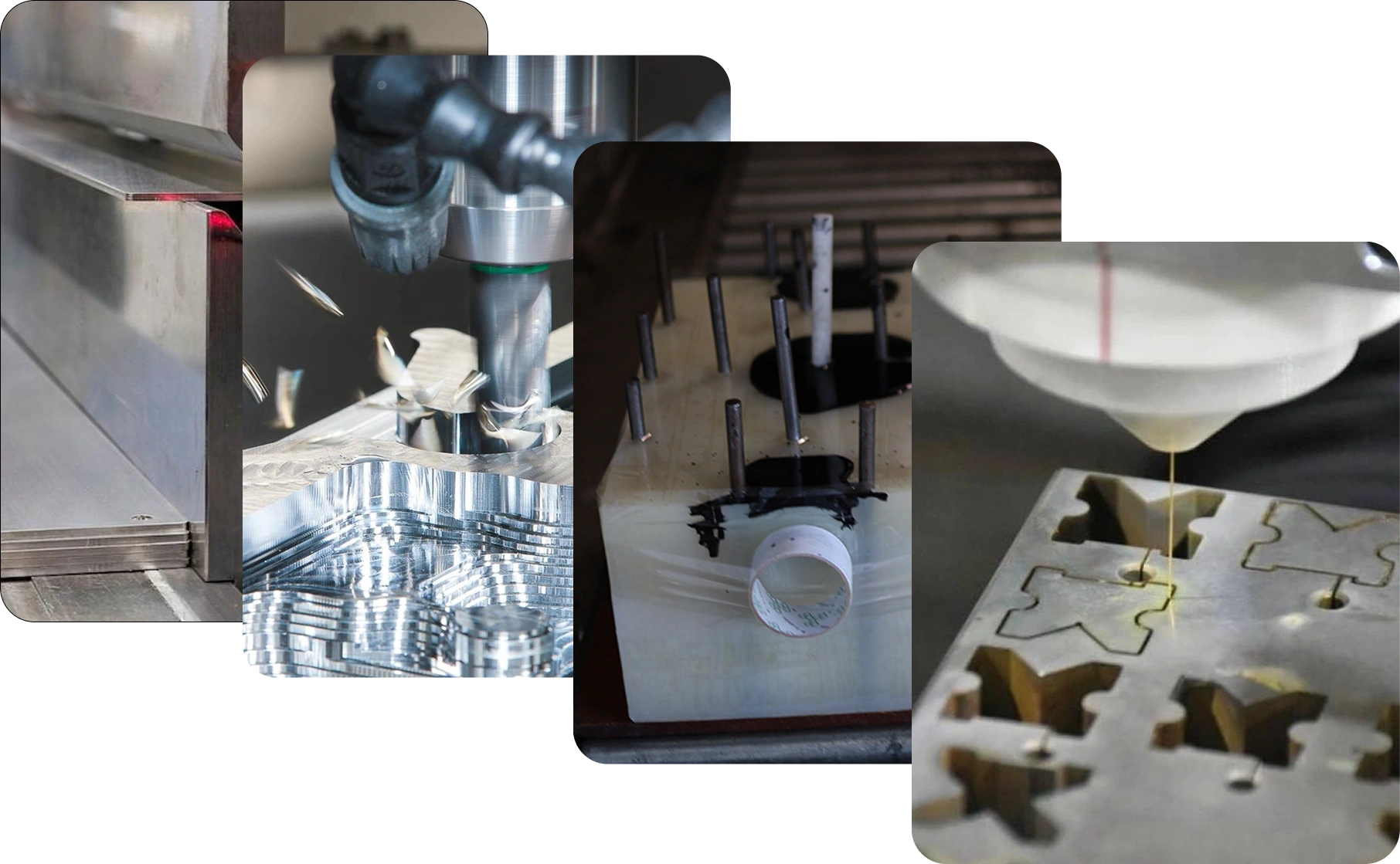
Choose your prototyping process.
Start with the part’s function, geometry and validation goal. Explore each service or compare the routes below.
CNC prototype machining
Functional metal and plastic parts from stock. Review tool access, threads, mating faces and critical dimensions.
3D printing
Complex shapes and early design iterations. Confirm printing process, build direction, supports and material behavior.
Sheet metal prototyping
Formed enclosures, panels and brackets. Review bend radii, hole clearances, hardware and assembly stack-up.
Vacuum casting
Small evaluation batches from a master and silicone tooling. Select a cast resin against the required properties.
Rapid tooling
Prototype or bridge tooling for evaluating a molded design. Review cavity requirements, tool material, expected quantity and ownership.
Injection molding
Molded parts for validation and pilot quantities. Review resin grade, draft, gates, shrinkage and cosmetic requirements.
Process specifications & engineering detail.
Review dimensions, feature geometry and validation conditions before selecting the manufacturing route.
Published service references come from the existing ProleanTech page and need project confirmation. Design starting points come from the linked manufacturers’ technical guides; they do not certify ProleanTech capability.
Published service reference · subject to drawing review
- Linear dimensions
- ±0.025 mm
- Unreamed hole / shaft diameters
- ±0.025 mm
- Published part envelope
- 950 × 550 × 480 mm
Approx. 37.40 × 21.65 × 18.90 in.
These are values on the existing ProleanTech page, not a blanket tolerance for every material or feature. Confirm setup access, fit classes and critical dimensions on the drawing.
Design starting points
- Walls: start at ≥0.8 mm for metals and ≥1.5 mm for plastics.
- Pocket depth: prefer ≤4× pocket width; standard drilled-hole depth: about ≤4× diameter.
- Allow internal corner radii and sufficient tool clearance. Deep pockets and thin walls need a specific review.
External technical design reference reviewed
Process-specific design example · not a ProleanTech machine specification
Specify SLA, SLS or another route before setting tolerances. Resin printing, powder processes and extrusion produce different support marks, surface texture and directional properties.
- SLA feature benchmark
- Form 4 / Grey Resin / 50 µm layers
- CAD wall / clearance
- 0.2 mm wall; 0.4 mm separation
- Hole / drain-hole diameter
- 0.5 mm / 0.75 mm
The figures above are external technical guide’ minimum-feature recommendations for that setup. They are not general printing tolerances or evidence of ProleanTech equipment. Thin features can warp; choose larger dimensions for robust functional parts.
Define with your enquiry
Material datasheet, build direction, support-contact faces, post-cure and assembly clearances. Layer height describes slicing, not finished dimensional accuracy.
External technical design reference reviewed
Published service reference · identify the feature relationship
- Same-face edge / hole relationships
- ±0.127 mm (±0.005 in.)
- Bend to edge / hole
- Published reference: ±0.254 mm (±0.010 in.); review the specific relationship
- Multiple-surface formed features
- Published reference: ±0.762 mm (±0.030 in.); not one rule for all formed dimensions
- Bend angle
- ±1° reference
external technical guide’ guide supports separate flat and formed-feature tolerances, but gives ±0.381 mm for a same-surface bend-to-hole relationship. Define bend-to-edge and bend-to-hole dimensions separately when requesting a quote.
Assembly consequence
A 50 mm flange with 1° angular deviation shifts its end by about 0.87 mm (50 × sin 1°), even before other tolerances. Define bend datums, sheet grade/thickness, inside radius and the finished assembly state.
External technical design reference reviewed
Master → silicone mold → polyurethane parts
Vacuum casting reproduces a master pattern in a silicone mold using a curing resin. It does not melt and remold the specified production thermoplastic.
- Batch planning
- Agree pieces per mold and replacement molds; tool life depends on geometry and resin
- Dimensional control
- Specify a feature-based tolerance after master, resin and shrinkage review
- Material selection
- Use the actual resin datasheet: hardness, strength, elongation, heat and aging behavior
Practical process boundaries
external technical guide describes roughly 50 casts as an example for one silicone mold, not a guaranteed yield. Master finish, split lines, gate marks and cure shrinkage affect the result. Define cosmetic faces and fit-critical holes.
Provide the overall part dimensions and minimum wall sections for feasibility review. Agree tolerances separately for fit-critical features; review master and resin shrinkage before batch release.
External technical design reference reviewed
A tooling strategy, distinct from molding the parts
- Prototype tooling
- Prioritize design evaluation, limited quantities and changes
- Bridge tooling
- Cover interim demand while a production route is qualified
- Production tooling
- Plan for agreed output, durability, maintenance and process control
Tool specification to agree
- Tool material and hardness; cavities, runner/gate system and cooling concept.
- Resin grade, fillers, anticipated shots, replaceable inserts and revision strategy.
- Tool ownership, storage, maintenance, sample approval and inspection records.
Aluminum and steel prototype tools can differ in heat transfer and molding behavior. If shrinkage or cycle behavior is being validated, discuss whether the proposed tool adequately represents production. No universal tool-life figure is assumed.
External technical design reference reviewed
Published mold reference · separate tool accuracy from part performance
- Mold cavity tolerance
- Published reference: ±0.05 mm
- Part-to-part repeatability
- Published reference: ±0.1 mm; feature and measurement method to be agreed
- Tool life / schedule
- Quoted per tool and resin; first samples, approval and batch production are separate milestones
DFM starting points
- Draft: about 2° is a general starting point; textured surfaces may need more.
- Example wall ranges: ABS about 1.14–3.56 mm; PC about 1.02–3.81 mm.
- Prefer consistent walls and gradual transitions; review ribs, bosses, gates and ejection marks.
Draft and wall figures are third-party design references, not guaranteed service limits. Cavity accuracy alone does not establish final-part accuracy: resin shrinkage and distortion must be considered.
External technical design reference reviewed
Compare processes before committing.
Choose the route that represents what you need to test. Material, geometry, quantity and inspection requirements are reviewed together.
| Process / service | Best starting point | Material & validation considerations | Review before manufacture |
|---|---|---|---|
| CNC machining ↗ | Functional parts and critical interfaces | Specified metal or engineering-plastic stock; grade and condition matter. | Tool access, setups, fits and thin walls |
| 3D printing ↗ | Complex geometry and early iterations | Process-specific materials; orientation and post-processing affect properties. | Build direction, supports and surface texture |
| Sheet metal ↗ | Enclosures, panels and formed brackets | Use the intended sheet grade, thickness and temper where relevant. | Bends, hardware and flat-pattern development |
| Vacuum casting ↗ | Repeated appearance or evaluation parts | Cast polyurethane is not automatically equivalent to the production thermoplastic. | Master quality, resin data and silicone tool life |
| Rapid tooling ↗ | Prototype molds and bridge tooling | Agree tool material and the intended molding resin; tool life is project-specific. | Cavities, revision allowance, quantity and ownership |
| Injection molding ↗ | Molded validation and pilot batches | Intended resin and molded features can support production-relevant evaluation. | Draft, gates, shrinkage and cosmetic acceptance |
Need to select a grade? Confirm the material after choosing the manufacturing route.
Prototype parts for your next design decision.
Specify what the prototype needs to prove: appearance, assembly fit or behavior under a defined load and environment. The manufacturing route should support that purpose.
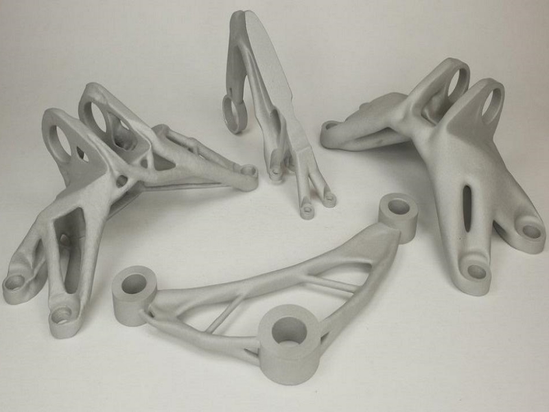
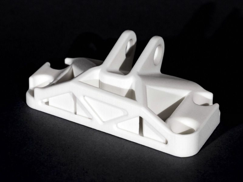
Form & presentation models
Review shape, appearance, handling and cosmetic surfaces. Define texture, color and presentation requirements separately from functional properties.
Fit & assembly prototypes
Check hole patterns, mating faces, fasteners, clearances and tolerance stacks. Identify critical datums and interfaces on the drawing.
Functional parts & pilot batches
Evaluate loads, temperature and operating conditions with an appropriate material and process. Printed and cast substitutes require a property review before representing production performance.
Photographs illustrate geometry and part types. They do not establish a specific material grade, manufacturing route or verified customer project.
Give the prototype a measurable acceptance plan.
Mark the dimensions that determine function. Provide the CAD model with a controlled 2D drawing when tolerances, datums or inspection requirements matter.
- Fits, datums & measurement
- Call out hole/shaft fits, position, flatness, sealing faces and thread standard, size and depth. Agree the datum setup, measurement method and reporting for critical features.
- Surface finish & coating allowance
- Specify Ra in µm where needed, the measurement surface and cosmetic faces. Mask mating features or account for finishing thickness; define whether critical dimensions apply before or after coating.
- Material condition & test purpose
- Specify alloy/temper or polymer grade, moisture conditioning where relevant, load, temperature and environment. A visually matching substitute is not automatically valid for a functional test.
- Revision, samples & batch approval
- Identify drawing revision, sample quantity, inspection report and approval hold points. Treat prototype acceptance and production-process qualification as separate decisions.
Define the inspection scope.
Agree the acceptance plan before manufacture. Dimensions, material records and cosmetic criteria should match the prototype’s purpose and the scope of your order.
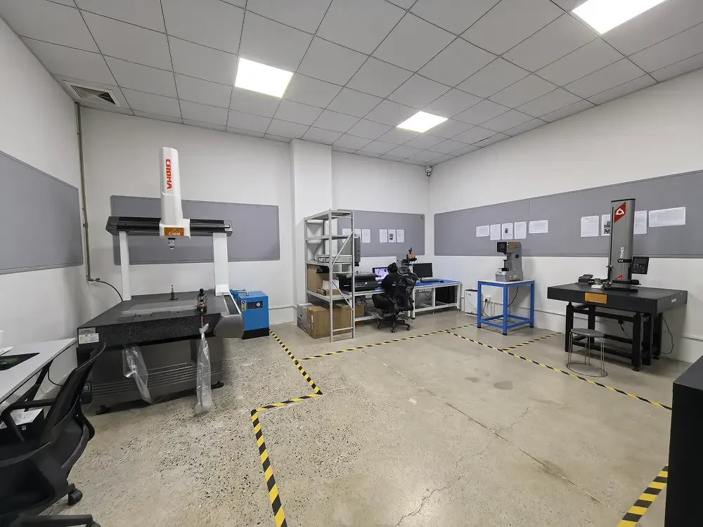
Check the features that determine fit.
Identify critical-to-quality dimensions, datum references and the measurement method. Confirm report content, sampling and any first-article requirements with your order.
A clear inspection scope.
- Dimensions & interfaces
- Critical tolerances, GD&T, threads and mating features.
- Material documentation
- Grade, traceability and certificates where required.
- Finish & appearance
- Cosmetic surfaces, color, texture and masking.
- Packaging & delivery
- Protection for sensitive surfaces and assembly features.
From design review to the next batch.
Send the design
Share CAD, drawing revision, quantity, test objective and delivery destination.
Confirm the route
Review DFM, material, finish, inspection, cost and the project schedule.
Manufacture & inspect
Produce against approved requirements and complete the agreed checks.
Evaluate & scale
Record test results, control revisions and review the route for the next batch.
Plan cost and lead time together.
Compare quantity breaks and separate tooling from part cost. Simplify noncritical features, consolidate finishes and confirm material availability. Freeze the drawing revision before production; include inspection and shipping in the schedule.
Rapid prototyping FAQs
What is a rapid prototyping service?+
It converts a CAD design into physical parts for form, fit, assembly or functional evaluation. CNC machining, 3D printing, sheet metal, vacuum casting and prototype molding serve different validation goals.
Which process is best for a functional prototype?+
Start with the property being tested. CNC machining can use specified stock materials; molding can use the intended resin. Printed and cast parts require a review of material properties, orientation and post-processing before they represent a production part.
How quickly can I receive prototype parts?+
The schedule depends on drawing review, material availability, geometry, quantity, tooling, finish and inspection. Ask for a manufacturing lead time and a separate shipping estimate. The confirmed quotation defines your project schedule.
What tolerances can you achieve?+
The published rapid-prototyping specification lists ±0.025 mm for specified dimensional features; sheet metal uses different values for flat and formed relationships. These are project references, not a universal tolerance. Printed, cast and molded parts need process-specific acceptance. Review the technical tables ↗
Can a plastic prototype use the same material as production?+
CNC-machined stock or injection molding may use the specified polymer grade, subject to availability. Printed materials and cast polyurethane substitutes can differ from production resins in strength, heat resistance, moisture response and aging.
Can you support low-volume manufacturing after prototyping?+
Yes, subject to the selected process. Rapid tooling creates the mold or tool; injection molding produces the parts. Agree cavities, resin, tool material, anticipated shots and sample approval before scaling. Rapid tooling service ↗
What affects prototype cost?+
Material, geometry, setups, tool access, quantity, finish, inspection and tooling all contribute. Separate essential functional requirements from cosmetic preferences, and quote quantities together to compare unit and setup costs.
Can I request an NDA before sending my CAD?+
Yes. An NDA is available for your project. You can also begin with a description of your requirements and arrange confidentiality terms before sharing sensitive files.
START YOUR PROJECT
Have a prototype design?
Let’s review it.
Send the drawing and tell us what the part needs to prove. We’ll review the manufacturing route and the requirements for your quote.
Confidential enquiries · Optional NDA ↗
Include with your enquiry
- 3D CAD and a dimensioned drawing, if available
- Material grade, finish and cosmetic surfaces
- Quantity, revision and critical tolerances
- Test purpose and inspection documents
- Required date and delivery destination