Flatness tolerance
Flat surfaces are critical in the manufacturing of mechanical parts to maintain their overall dimensional stability. In engineering drawing, it is expressed in terms of flatness tolerance, which measures the surface deviation relative to a perfectly level plane.
Controlling the flatness ensures the manufactured parts align and fit correctly during assembly. Subsequently, it is also essential for optimal load distribution and precision of assembled parts. That’s why it is clearly considered and labelled in designs with a standard flatness GD&T symbol and tolerance values, called “callout”.
The upcoming sections of this article will illustrate the GD&T flatness symbol, tolerancing in design, the benefits of considering flatness, and how to measure the flatness of a surface.
Let’s get started.
Flatness Definition and GD&T Flatness Symbol
Flatness is a geometrical control that defines the uniformity of a plane surface in parts made using sheet metal fabrication, CNC machining, casting, molding, or any other process. For quality control purposes, the flatness must fall within the specified tolerance level outlined in the design.
What is flatness tolerance?
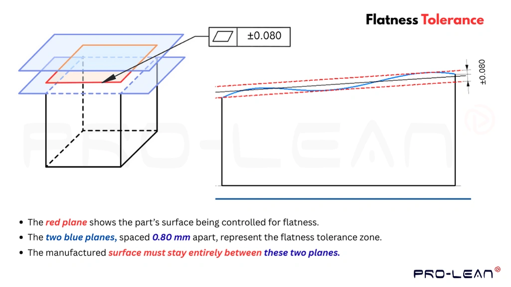
In a 3D space, a designer fixed two virtual parallel planes above and below a reference surface, and the feature must lie between those two lines after manufacturing. So, the flatness tolerance defines allowable deviation from the perfectly flat(reference) surface.
Flatness might seem similar to parallelism, but it is a form type tolerance, unlike parallelism orientation. Parallelism geometric tolerance is relative to the reference datum and controls how parallel the surface or axis is relative to that datum. Flatness is not connected to any datum, independent of its position and orientation with respect to other geometrical features.
How to Show GD&T Flatness Symbol in Design?
Flatness symbol
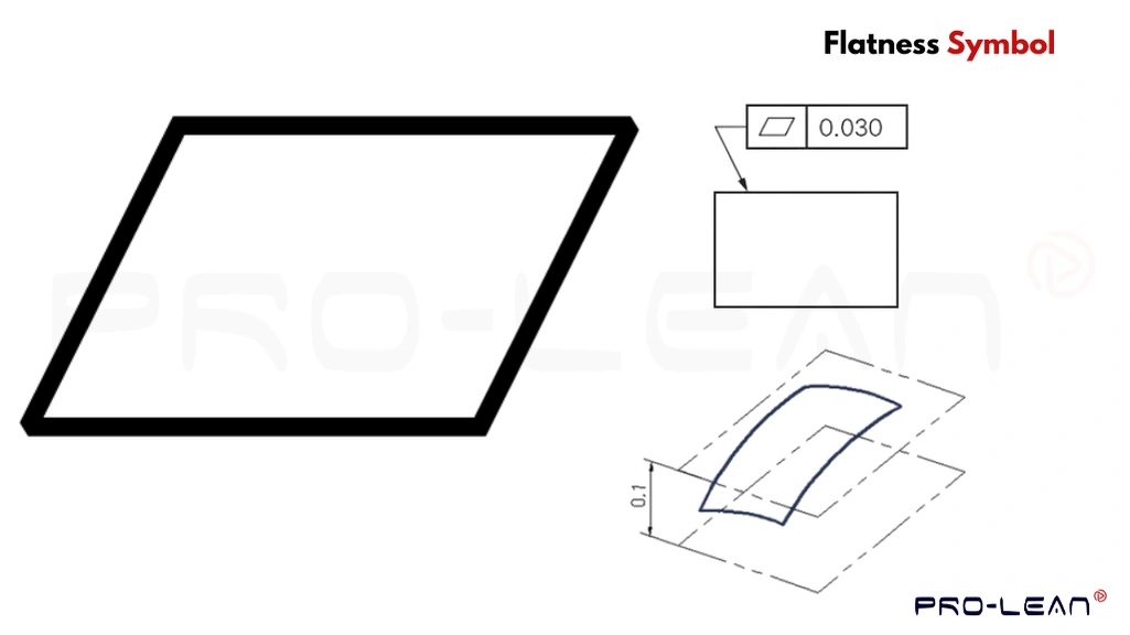
There are standard practices regarding symbols for each type of tolerance in engineering designs, such as flatness, straightness, cylindricity, and circularity. The flatness tolerance callout is indicated with a diamond-shaped parallelogram (▱), followed by the tolerance value inside a box.
“Flatness GD&T Definition—It is a type of tolerance that controls the allowable range that a surface can deviate from a perfectly flat plane.”
In the design, its “GD&T Callouts ” are placed either on the top of the surface or with a dimensioning extension line. However, you can also apply them as a derived median plane or per unit local flatness.
Do you have your design ready and need help with GD&Ts and other optimizations? Talk to our experts now.
Maximum Material Condition (MMC Flatness)
Flatness at MMC
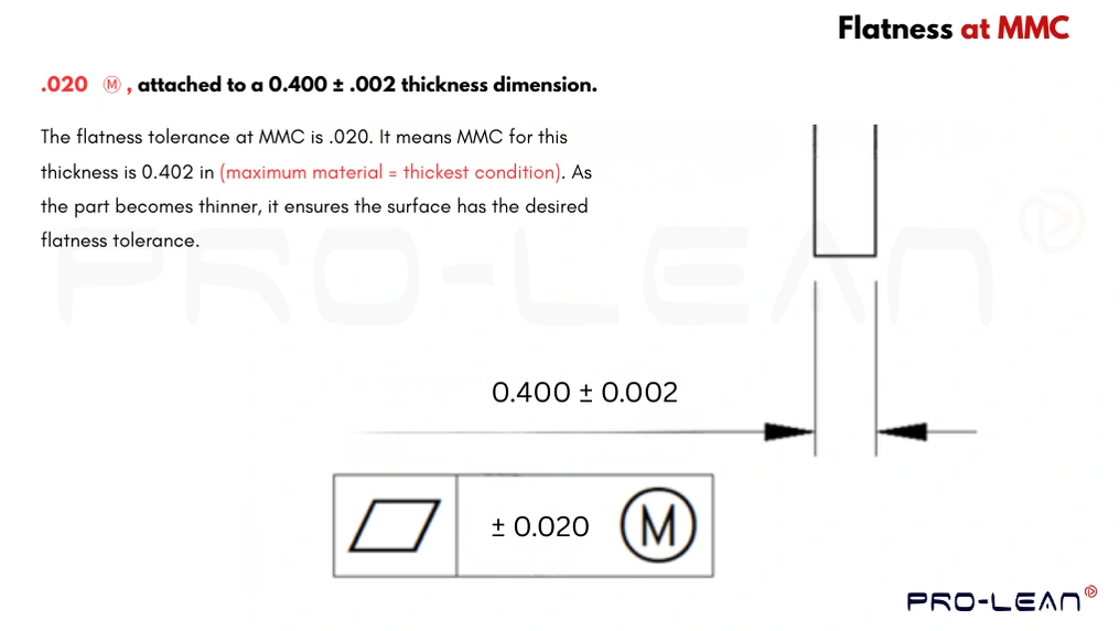
The flatness of the maximum material condition does not control the surface directly; instead, it controls features of size via the derived median plane. MMC defines the limit of maximum material by width and thickness. So, if the features become smaller (material lies towards LMC), the part meets the tolerance requirement.
Using flatness at MMC is typically beneficial for correctly stacking the parts, alignment, and when tight control is required for small features. E.g., precision sheet metal prototyping, stacked spacers, gearbox assembly, and sliding guides.
How to Measure Flatness of a Surface?
Flatness measurement is essential to ensure that the parts are manufactured with the allowable deviation mentioned in their design. So, parts can deliver the intended performance, fit, and stress distribution.
Let’s discuss four key flatness measurement methods.
Using the CMM Machine
A coordinate measurement machine (CMM) is advanced equipment that utilizes probes and sensors. It tracks and measures Cartesian coordinates across a surface. While measuring the flatness, the probe touches and scans multiple points on the surface.
Software analyzes those coordinates and generates a best-fit plane (a perfectly flat surface). Comparing the local points with this software-generated virtual plane, it finds the maximum deviation.
Surface Plate and Height Gauge
The surface plate serves as a reference plane for measuring the flatness deviation of the substrate surface. It is situated and secured below the part. A height or dial gauge moves across multiple points on the measuring surface, and its base slides on the plate. Then, variations are monitored and recorded to find the maximum deviation.
If the plate has any inclination or is not placed over a flat surface, it can result in wrong measurements. Moreover, this method is well-suited for quickly measuring the flatness of small parts.
Functional Gauge
The functional gauge simulates how the part will behave during mating or in its intended application. It involves the use of two height gauges, one at the top and one at the bottom of the surface. They measure local thickness values over the surface, and then those values are interpreted to determine whether they fall within the allowable flatness zone or not.
Optical Measurement
It uses different optical waves to scan the measuring surface with a high number of local points using laser scanners, interferometers, and profilometers. Unlike other methods, it can be used for large parts with high accuracy and speed.
The light waves are projected on the surface, which strikes and is reflected to form a height profile. Then, the highest and lowest points on the surface can be analyzed to determine the flatness tolerance.
Try Prolean Now!
Flatness Vs Other Types of Form Tolerances
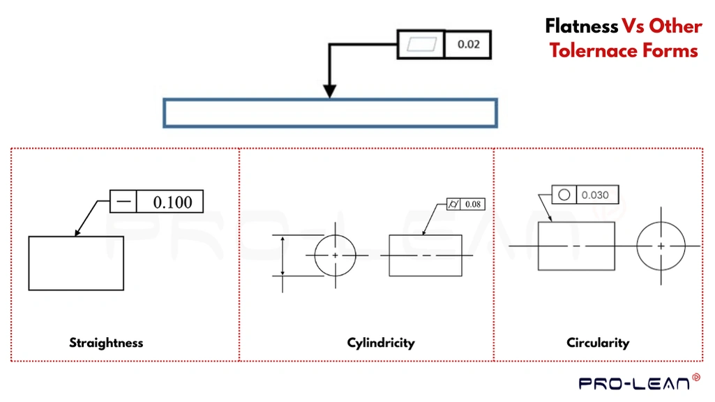
Flatness Vs other tolerance forms
Besides flatness, there are three other types of form tolerances used in sheet metal drawing or other manufacturing designs: straightness, cylindricity, and circularity. Each of the control forms or shapes of the feature has no relation to other features.
Let’s compare them for a clear understanding:
Straightness vs Flatness
Like flatness is controlled by two parallel planes, straightness control is achieved through two parallel straight lines. It determines whether a feature is deviated within the defined tolerance range within the referenced straight line or not.
The symbol of straightness tolerance is indicated by a straight dash (—), followed by the value, referencing a straight line or axis.
Cylindricity Vs Flatness
Cylindrical tolerances are used to control the deviation of any cylindrical feature with respect to a perfectly cylindrical geometry. So, cylindricity defines how close a feature is to the true cylinder. Typically, these are tighter than the diameter tolerances of the feature or part.
Circularity Vs Flatness
Circularity is used to control the form of features having a circular cross-section. This tolerance defines the permissible deviation from a perfect circle form. How flatness uses two parallel planes, it uses a zone defined by two perfect circles, and the measurement after manufacturing must fall under this zone.
Advantages of Using Flatness Tolerance
Below are the primary benefits of incorporating flatness tolerance into your engineering designs.
- Dimensional Stability: It helps to control the surface features and forms, an essential aspect for the overall dimensional stability of parts & products.
- Assembly Precision: Flat surfaces are crucial for precise mating with other parts, ensuring alignment and a perfect fit in mechanical assemblies.
- Performance: Flatness is crucial for the functionality and performance of various sheet metal processing parts.
- Surface Finish: Flatness also controls the waviness and irregularities, reducing the roughness value and enhancing the smoothness.
- Uniform Load Distribution: A uniform surface prevents localized stress concentration, which helps to avoid any surface defects and local material failures.
Try Prolean Now!
Do You Need On-Demand Custom Parts? Quote us Today
Producing parts and products meeting all design tolerances is crucial for their functionality and performance. For this, you need a well-optimized design, advanced manufacturing equipment, expert manpower, and strict quality control procedures —we ensure all of these requirements at Proleantech.
We operate an advanced machine shop equipped with automated CNC machines, metal fabrication equipment, and calibration systems, overseen by expert engineers. Additionally, we also help in the design optimization for manufacturability and precision.
So, upload your design and request a quote today.
Read More:
Key Takeaways
- Flatness geometric tolerance (GD&T) limits the deviation of surface forms from a perfectly flat plane, symbolized by ▱.
- The surface measurement must fall within the zone of two parallel planes to meet the specified tolerance.
- Flatness and other form tolerances are tools for engineers and manufacturers to control the different production requirements.
- If you are outsourcing the sheet metal fabrication services, you need to ask the manufacturer about precision capabilities before finalizing the flatness tolerance.
FAQs
What is the 3/2/1 rule in GD&T?
It is a rule for fixing the location of a feature (or part) in the design along six degrees of freedom. It includes three points on the primary plane, two on the secondary plane, and a single point of contact.
How is flatness tolerance defined?
A flatness tolerance is defined as an allowable deviation of the surface to lie between two perfectly flat parallel planes (called “tolerance zone”).
What are the four types of tolerances?
The four types of tolerances are: unilateral, bilateral, GD&T, and limit.


0 Comments