
APPLICATION / ELECTRONICS
Electronics & thermalElectronics and thermal parts.
Heat sinks, enclosures and precision connectors.
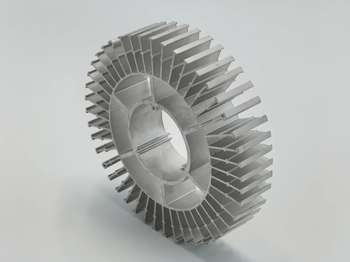
Heat sinks, equipment enclosures and connector bodies where the thermal path, wall thickness and mounting interface decide the design. We machine to the fin geometry, flatness and finish you specify.
- TYPICAL PARTS
- Heat sinks, enclosures, connector bodies, mounting plates
- PRIMARY ROUTE
- CNC milling, CNC turning, sheet metal enclosures
- COMMON MATERIALS
- Aluminium 6063 and 6061, copper, brass, stainless steel
SPECIFICATION
APPLICATION REQUIREMENTS
What decides the design here.
Four things shape the route before a tool is selected. If any of them is unknown at enquiry, we say so instead of assuming a default.
Read the design guideThermal path
Where heat enters, where it leaves, and the interface material between them. Fin height, pitch and base flatness follow from this.
Wall thickness and stiffness
Minimum wall section, panel deflection and the fastener positions holding the enclosure together.
Mounting interface
Bolt pattern, connector cut-outs and the faces that must sit flat against the board or chassis.
Finish and electrical behaviour
Anodizing, plating or conversion coating, and whether a surface has to conduct or insulate.
PARTS WE MAKE
Parts for this application,
and the geometry that shapes them.
Workshop photographs of real geometry. Each one carries the route, what the machine has to reach, what is checked, and what you need to state on the drawing.
See more part geometry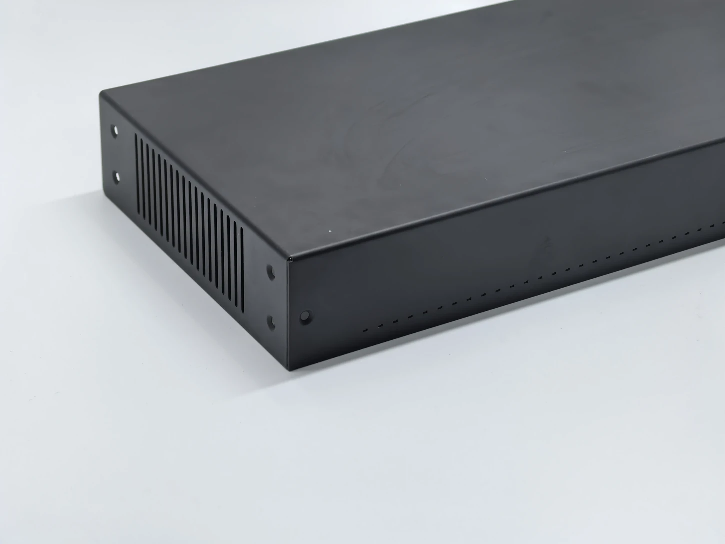
Vented enclosure
Vent geometry, panel joints and the flatness of the faces that seal. Vent pattern and sealing face flatness are set together, because cutting vents relaxes the panel.
Specify the vent pattern, the sealing faces and the coating requirement.
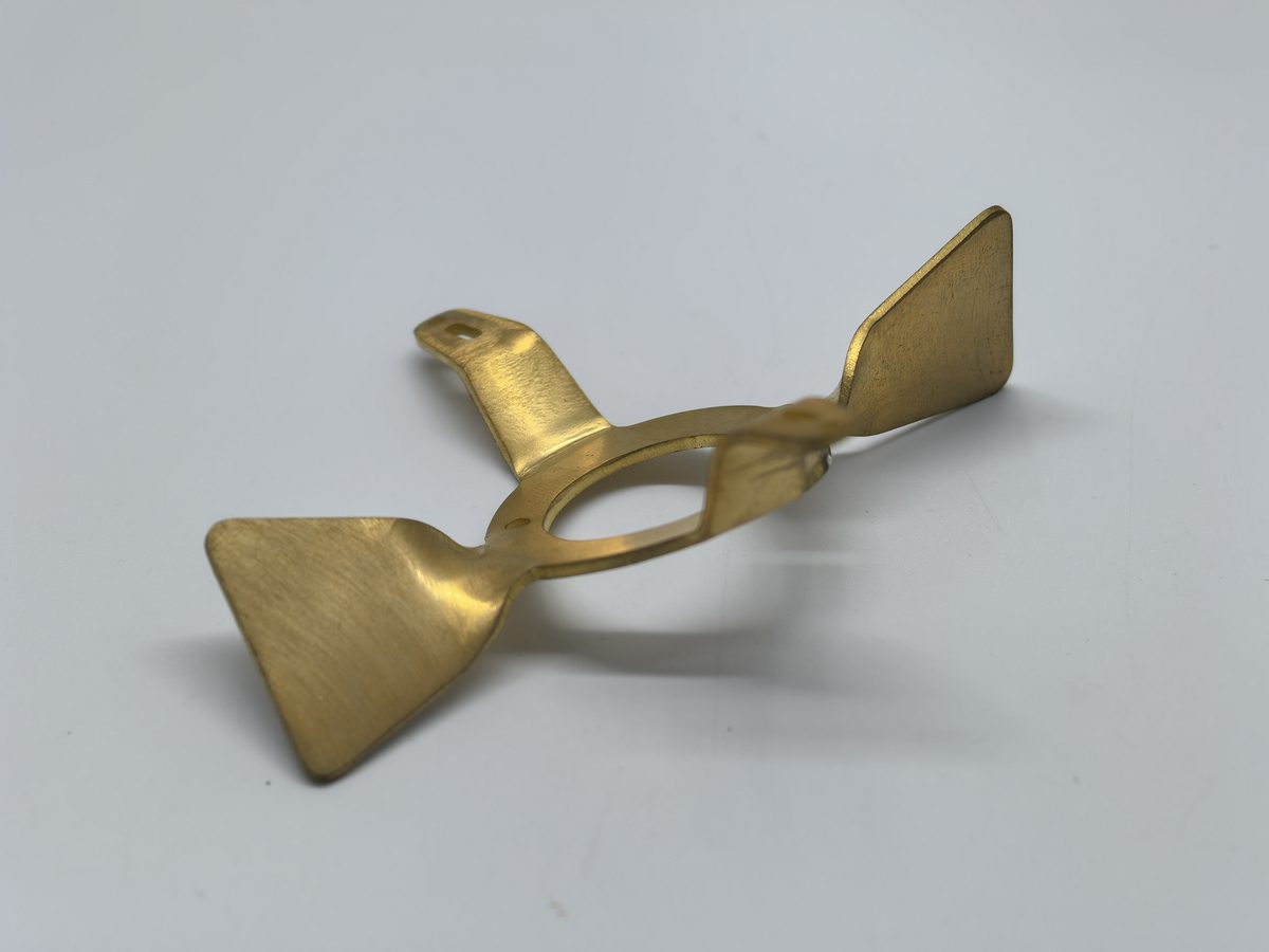
Formed brass bracket
A central bore that locates the component and three formed arms that carry the mounting holes. Flat brass moves when it is cut, so hole position and flatness have to be set together.
Give the material and thickness, the hole pattern after forming and any plating requirement.
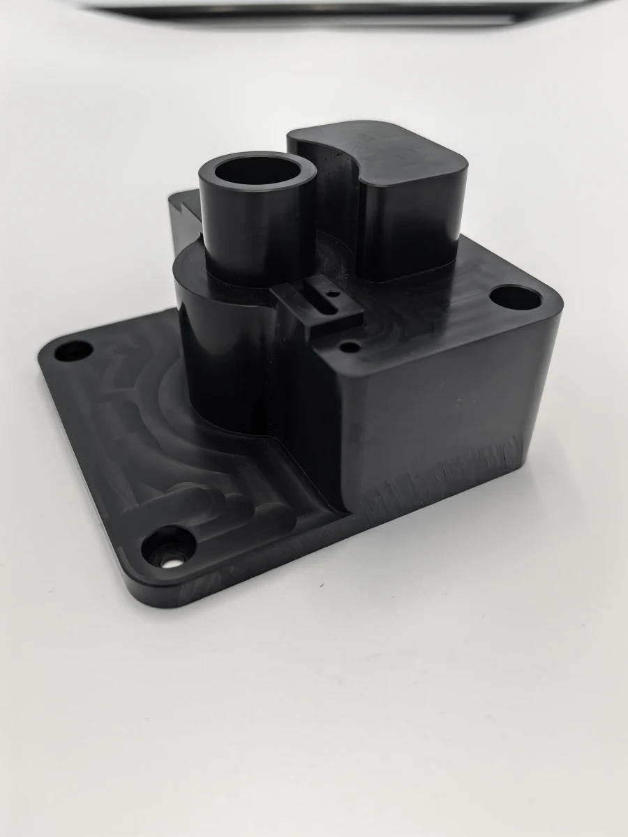
Mounting plate with bosses
Boss height, hole position and the flatness across the mounting face. Tall bosses on thin plates pull the face out of flat when they are machined last.
Mark the mounting holes, the datum face and any finished thickness.
Size the heat sink before you detail the fins.
Heat Sink Size Calculator
For an open-air passive design, estimate the width, clear fin spacing and number of fins from your heat load and allowable base temperature.
- Define the thermal conditions.Enter actual heat loss, ambient temperature and the maximum sink/base temperature.
- Explore a geometry that fits.Adjust length, fin height, thickness and emissivity; save up to three concepts for comparison.
- Bring the concept to the drawing.Export the sizing report, then submit CAD, material, finish and quantity for a manufacturing review.
This estimates a full-base heat source with vertical fins, natural convection and radiation. Small chip sources, enclosed products and fan cooling need separate analysis. Manufacturing review does not validate thermal performance.
PROCESSES, MATERIALS AND FINISHES
The routes used for these parts.
Not every route suits every part. These are the ones that come up most for this application; the quote states the route chosen for your geometry and quantity.
All capabilitiesFINISHES AND TREATMENT
Finishing changes dimensions: coating thickness, masking and any effect on a mating fit are agreed before the route is fixed, not discovered at inspection.
INSPECTION AND DOCUMENTATION
What we measure, and what we record.
The inspection scope is agreed with the order. Anything you need recorded has to be stated before machining starts, because it cannot be reconstructed afterwards.
Tolerancing standards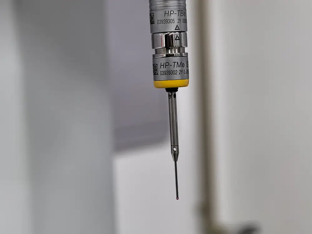
Dimensional inspection
Datums, bore sizes and mounting patterns measured against your drawing, with the method agreed before production.
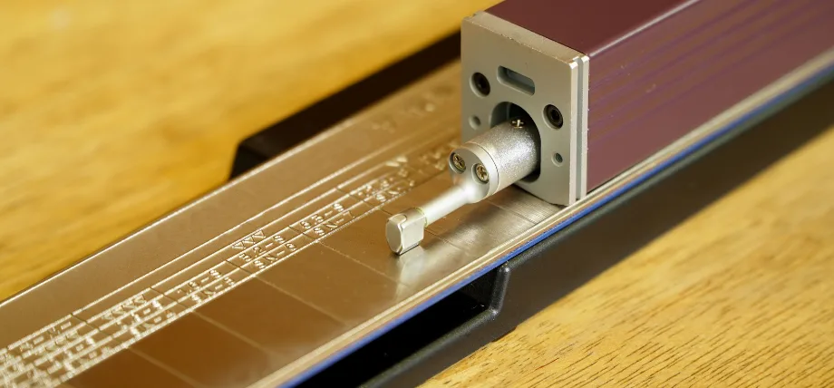
Surface roughness
Roughness measured where the drawing calls it out, on sealing, sliding and contact faces.
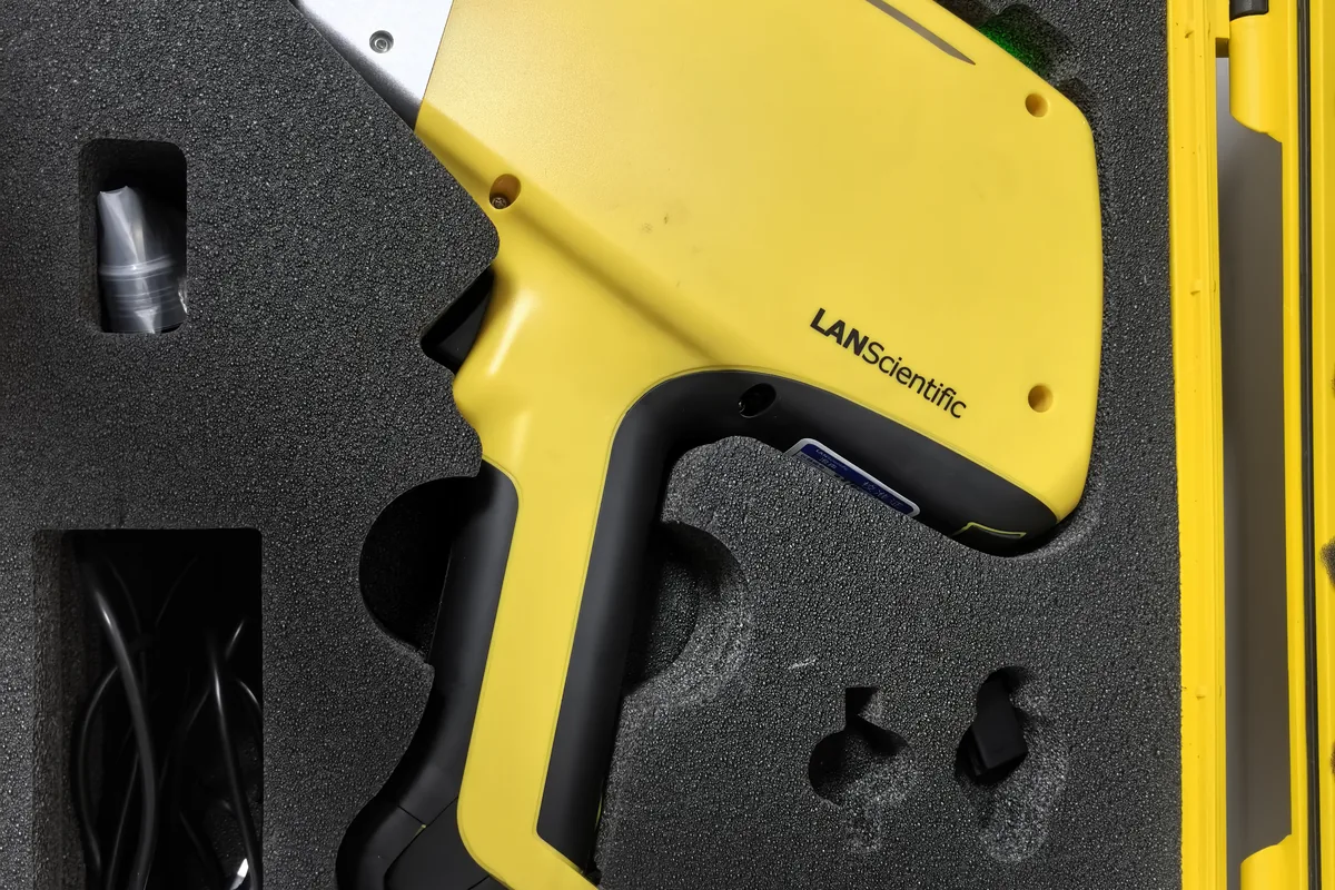
Material verification
Alloy grade checked before machining. Certificate scope is agreed with the material order, not added afterwards.
Where a programme requires verification we cannot give in-house, independent third-party testing or inspection can be arranged. The scope and the cost are agreed in the quote, not added later.
AGREED BEFORE THE ORDER STARTS
- 01Drawing revision and the thermal or electrical requirement it states
- 02Flatness call-out and the measurement method for it
- 03Material grade and the certificate source
- 04Finish specification and any masking or conductivity limits
- 05Cosmetic acceptance on visible enclosure faces
- 06Packing that protects finished and coated surfaces
APPROVED CASE STUDIES
Case studies for this application.
A case study needs approved objective, process, inspection and result records. We do not publish a project until that approval exists.
Case studies are being prepared for publication.
The part photographs above are workshop images of real geometry. They show what can be made, not a completed project: material, tolerance, quantity and delivery results are published only where the customer has approved the record. Until then, the fastest way to see whether your part fits our route is an engineering review.
QUESTIONS
Electronics questions.
The questions that come up for this application. Anything not covered here goes to an engineer.
How flat can the base of a heat sink be?
We work to the flatness you specify. Tighter flatness needs a defined machining route and a measurement method agreed in advance – state both on the drawing.
Can you machine fin pitches below 1 mm?
It depends on fin height and the tool available. Send the fin geometry and we will confirm what the tool can reach before quoting.
Do you make enclosures with vents and cut-outs?
Yes, by machining or by sheet metal with laser-cut openings. The route depends on quantity and panel thickness.
Will anodizing affect the fit of my enclosure?
Anodizing adds thickness and changes dimensions slightly. Masking and dimensional allowances are agreed before the route is fixed.
Do you assemble hardware into enclosures?
We manufacture the enclosure and its metalwork. Assembly scope is confirmed case by case at enquiry.
START WITH YOUR DRAWING
Bring your next part
to an engineering review.
Send CAD or a drawing, quantity, material and critical requirements. We will review the manufacturing route, price and lead time.