
CUSTOM COMPONENTS · REPEAT PRODUCTION
Metal Stamping
Services
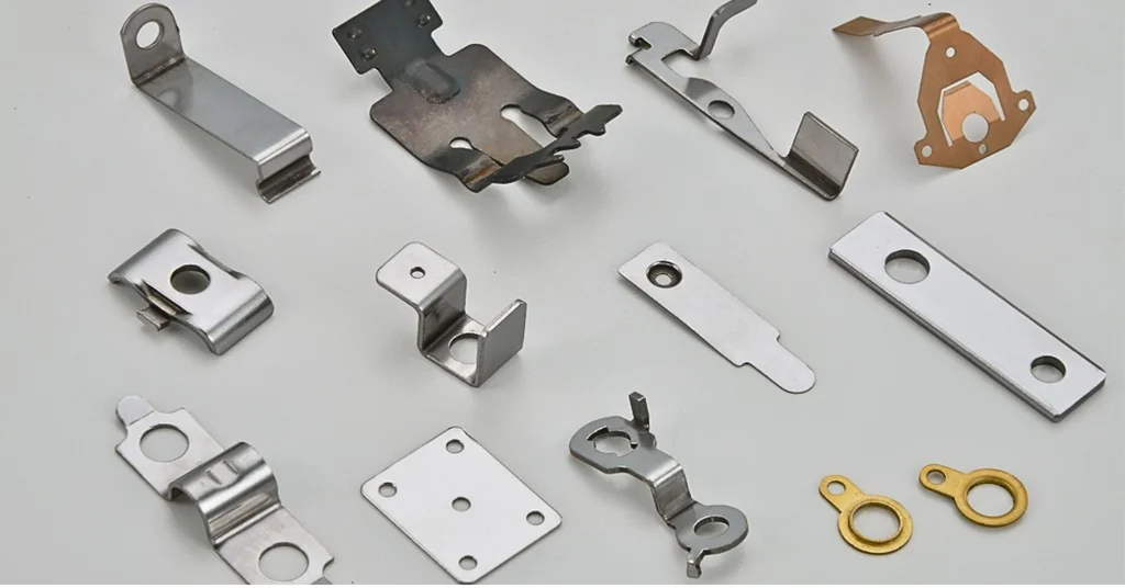
Custom stampings for brackets, contacts and formed hardware. Plan tooling, materials, finishing and inspection around your drawing and production volume.
Your drawings stay confidential. Optional NDA available ↗
CUT · FORM · FINISH
Build the manufacturing route
around your part.
Metal stamping uses press tooling to cut and form sheet or strip. The operation sequence determines which features can be combined, where secondary work is needed and how the part will be inspected.
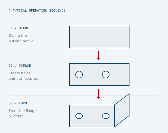
Blanking & piercing
Cut the outer profile and create holes, slots or notches. Review small features, narrow webs, material utilization and the permitted burr side. Cut-edge condition is part of the specification.
Bending, flanging & embossing
Add formed walls, offsets, flanges or raised features. Material condition, grain direction, radii and springback affect the finished geometry and the required tooling.
Progressive die stamping
Sequential stations can combine cutting and forming on a fed strip. For stable repeat demand, review strip layout, carrier design, tooling investment and maintenance against the part’s lifetime quantity.
Secondary operations & finishing
Review deburring, specified machining or threading, joining, plating and coating as part of the complete component. Confirm tool access, processing sequence and final inspection requirements.
Have a drawn cup, a deep feature or a complex forming sequence?
Send the drawing for a dedicated feasibility review. Transfer, deep-draw and specialty tooling requirements are confirmed individually.
From the part’s function
to its manufacturing details.
Source mounting hardware, electrical contacts and formed components with the geometry, material and finish your assembly needs.
Typical applications include electrical hardware, electronics, equipment mounting and appliance components. Include any industry-specific testing or qualification requirements with your inquiry.
Make tooling investment
a production decision.
A lower price per piece is only one part of the decision. Compare tooling, trials, material use, secondary work and the cost of a future design change.
Prototype & design changes
For early fit checks, compare laser cutting and bending before committing to dedicated dies. A fabricated prototype may validate fit without reproducing production stamping behavior.
Pilot & initial production
Review practical tooling and setup options against the first order. Agree samples, critical features, any tool changes and the approval criteria before the production batch.
Stable production demand
Evaluate dedicated or progressive tooling when forecast quantity supports it. Establish the approved revision, tool maintenance responsibility, inspection plan and repeat-order schedule.
What drives the stamping quotation?
Material grade and thickness · blank layout and scrap · feature count and forming complexity · die construction · setup and trial work · deburring, machining or assembly · plating and masking · inspection scope · quantity and delivery.
There is no universal break-even quantity. Share initial, annual and expected lifetime demand, plus the likelihood of a drawing revision.
Specify the material.
Include its condition.
Sheet grade, thickness and temper affect forming, springback, tool wear and final function. Choose a sheet grade and condition that suit your component. We confirm material availability and forming suitability with your quotation.
Swipe to compare material considerations →
| Material family | Material grades | Engineering considerations |
|---|---|---|
| Aluminum Material guide |
5052, 5083; ask about other sheet alloys | Lightweight formed parts. Specify temper, bend radius and cosmetic faces. A tight bend suitable for one alloy or condition may not suit 6061-T6. |
| Stainless steel Material guide |
301, 304, 316 / 316L | Specify grade and condition for corrosion resistance, forming and any spring function. Review work hardening, springback and surface protection. |
| Cold-rolled & low-carbon steel | SPCC, 1008, 1010 or a specified sheet standard | Brackets and formed hardware. State the sheet standard and surface condition. Select a protective finish for the service environment. |
| Copper Material guide |
C101 / C110, specified condition | Electrical and thermal components. Define conductivity, contact faces, flatness and plating requirements. Mechanical behavior depends on temper. |
| Brass Material guide |
Specified sheet alloy and temper | Contacts and formed hardware. Review sheet availability and formability. A free-machining bar grade is not an automatic sheet-metal substitute. |
Need nickel alloy, spring stock or another special grade? Include the exact specification for a separate sourcing and forming review. No material substitution without your approval.
Plating & finishing
for stamped components.
Choose the system for the substrate and function. Define coating thickness, contact areas and acceptance after finishing, especially where a coating can alter fit or electrical performance.
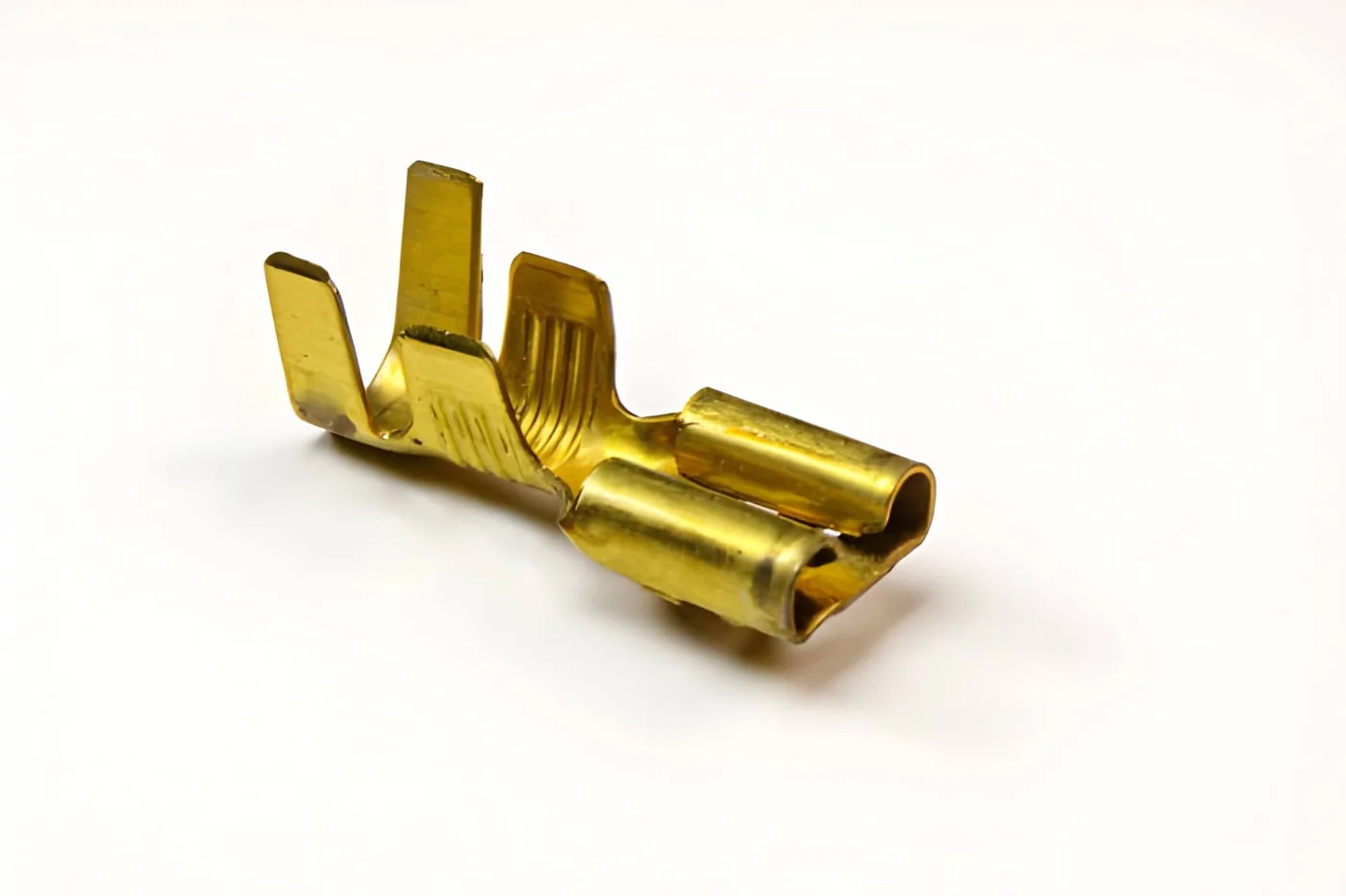
Specify the base alloy, plating system and contact requirements for your electrical component.
Deburring & controlled edges
Define burr direction, permitted burr height, edge break and surfaces that must remain sharp or flat.
Metallic plating
Specify the metal, underplate, thickness and masking. For steel corrosion protection, review zinc plating; for contact or wear requirements, define the appropriate nickel or other system and tests.
Anodizing & conversion coating
Options for compatible aluminum alloys. State type or standard, color, electrical contact areas and dimensional requirements.
Passivation & powder coating
Review passivation for compatible stainless steel, or powder coating for a specified protective and decorative system. Define preparation, masking and appearance criteria.
Inspect the finished component, including its interfaces.
Mark grounding points, contact faces, threads, press fits and spring features. Specify which dimensions apply after finishing and any required coating or corrosion testing.
Resolve the forming risks
before the die is made.
DFM connects the finished drawing to the strip, blank and tooling. Highlight the function of critical features so tolerances and process choices follow the real assembly needs.
Holes, slots & narrow webs
Review feature width and spacing relative to material thickness and strength. Holes near a bend can distort; small punches and thin webs can raise tooling and maintenance risks.
Radii, grain & springback
Specify inside radii, bend direction and finished angle. Tight bends can crack or vary with material condition. Springback compensation may need tool trials and adjustment.
Burr side & cut-edge condition
Pierced and blanked edges include shear and fracture zones. Identify the allowed burr side, assembly direction and any edge that needs controlled deburring.
Flatness, datums & formed dimensions
Reference the surfaces and holes that locate the part in service. Review flatness and dimensions across bends separately from features on a single flat surface.
Function after plating or heat treatment
For spring or electrical parts, specify functional acceptance and process sequence. Coating build, thermal processing and forming can affect the final requirement.
SPECIFICATION · VERIFICATION · RECORDS
Quality starts with the drawing.
Acceptance follows the finished part.
Blank geometry, formed dimensions and functional performance are different requirements. Define how each will be checked before production is released.
01 / Confirm the controlled specification
Agree drawing revision, material, thickness, critical features and finish. Thickness range, part size and achievable tolerances are confirmed for the selected material and route.
02 / Review samples & first articles
Agree trial or first-article requirements, dimensional records and the approval point before the production lot proceeds. Record any deviation or drawing change.
03 / Match inspection to the feature
Optical measurement can support profiles and hole relationships; height measurement supports datum-based features. Formed angles, flatness, contact force or assembly fit need appropriate methods and an agreed sampling plan.
04 / Define the delivery documents
Request material certificates, dimensional reports, finish records and lot traceability when required. Scope and availability must be confirmed with the order.
Your drawing and quotation define the agreed tolerances, inspection methods and acceptance requirements for the finished component.
From RFQ to a controlled
production release.
Work with ProleanTech in Shenzhen, China. Share the engineering and purchasing requirements together so the quotation covers the complete component.
-
Share the part
Drawing, model, material, quantity breaks and delivery destination. Flag open design questions.
-
Agree the route
Review DFM, tooling, piece price, finishing, inspection and the development schedule.
-
Approve the sample
Confirm the required first-article evidence and close any revisions before lot release.
-
Inspect & deliver
Follow the agreed acceptance plan and protect edges, contact faces and finishes for shipment.
Metal stamping
questions, answered.
Practical answers for sourcing teams and engineers evaluating a stamping project.
What is custom metal stamping?
Custom metal stamping uses a press and dedicated punch-and-die tooling to cut or form sheet or strip into a specified part. Blanking creates the outside profile; piercing creates holes. Bending, flanging and embossing add formed features. The route depends on the geometry, material and order volume.
When should I use stamping instead of laser cutting and bending?
Stamping is worth evaluating when the design is stable and repeated demand can justify dedicated tooling. Laser cutting and press-brake bending can be more practical for early prototypes, changing designs or small quantities. Compare tooling, unit price, secondary operations, expected lifetime quantity and revision risk.
Do you offer progressive die stamping?
Progressive die stamping is a route for review when a strip can advance through sequential operations while the parts remain attached to a carrier until cutoff. Send the part drawing, material and forecast quantity so ProleanTech can confirm tooling feasibility and the production route in the quotation. We’ll assess the tooling route against your part geometry and repeat demand.
Which materials can I specify for stamped parts?
You can specify aluminum, stainless steel, cold-rolled or low-carbon steel, copper and brass for your stamping inquiry. Specify the exact sheet grade, thickness and temper or condition. Availability and formability are confirmed for the project; nickel alloys and other special materials require a separate feasibility review.
What thicknesses, sizes and tolerances can you support?
Submit the drawing and identify critical features. Feasibility depends on material strength, thickness, blank size, geometry, tooling and press requirements. Flat pierced features, dimensions across bends and finished-part flatness require separate review. The drawing and accepted quotation define the agreed limits.
Can stamped components be plated or coated?
Yes. Include plating or coating in your stamping inquiry so the quotation covers the finished component. Specify the base material, coating system, thickness, masked contact areas and final dimensional requirements. For electrical parts, define conductivity and any tests. For formed or high-strength parts, flag coating integrity and any required embrittlement-control requirements for review.
Is there a minimum order quantity or a fixed delivery time?
Minimum practical quantity and lead time are project-specific. New tooling, trials, first-article approval, material procurement, finishing and inspection all affect the schedule. Include your initial quantity, repeat forecast and required date so the quotation can separate tooling development from repeat-production timing.
What files and documents should I send for a quote?
Send a dimensioned 2D drawing, a 3D CAD model if available, units and revision. Include material grade and condition, thickness, quantity breaks, finish, critical dimensions, inspection documents and delivery destination. Add assembly or functional requirements where the drawing alone does not describe acceptance.
YOUR NEXT STAMPED COMPONENT
Bring the drawing.
Let’s work through the details.
Get a drawing-led review of your part, tooling and production requirements. Include your forecast quantity so we can assess the full manufacturing route.
Your drawings stay confidential. Optional NDA available ↗