
HOLES, SLOTS & REPEAT PATTERNS
Sheet Metal
Punching Services
Custom panels, brackets and enclosure parts. Align hole patterns, edge condition and downstream fabrication with your drawing and order quantity.
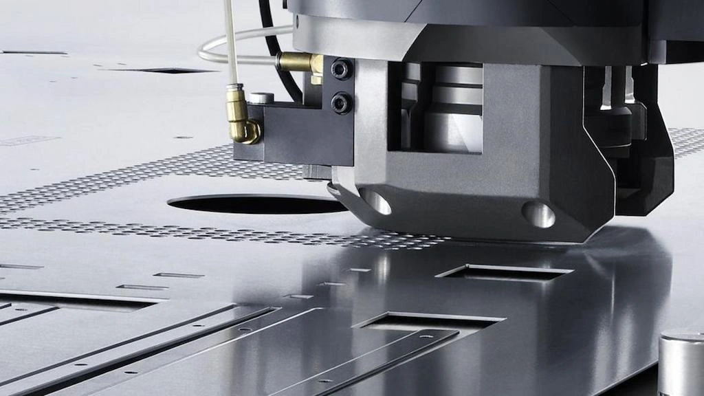
Order the openings.
Define the whole part.
A punched component is more than a hole count. Use your inquiry to define the mounting interfaces, the open area and the finished surfaces that make the part work in its assembly.
Panels & enclosure plates
Locate connector cutouts, fastener holes and ventilation patterns from common datums. State cosmetic faces, panel flatness and any areas that must stay free of tool marks.
Brackets & mounting interfaces
Define hole-to-hole position, slot width and the relationship to bends. For slotted adjustment, specify the usable travel and the mating fastener rather than only the outside slot length.
Perforated & patterned parts
Provide pitch, pattern boundaries and unperforated margins. Open area, narrow webs and repeated hits affect sheet stability; confirm flatness and any forming after punching.
Punching, piercing and blanking
In piercing, the sheet surrounding the opening is retained and the slug is waste. In blanking, the removed blank is the desired part. Here, the buying focus is pierced sheet metal components with specified holes, slots and patterns.
Choose the route around geometry and demand.
Compare tooling, material, quantity, edge quality and secondary work together. Punching is a mechanical shearing process; avoiding a thermal cut does not eliminate burrs or deformation.
| Route | When to evaluate it | What changes the decision |
|---|---|---|
| Sheet metal punching | Repeated holes, slots and hole arrays in panels or brackets. | Available tools or special shapes, total hits, material strength, web width, burr control and flatness. |
| Metal stamping ↗ | Stable designs combining repeat cutting and forming with dedicated tooling. | Tool investment, trial approval, lifetime quantity, design revisions and repeat-order economics. |
| Laser cutting ↗ | Flexible contours, changing designs or openings that would require special punch tools. | Thermal effects, cut edge condition, feature size, material and finishing or forming requirements. |
| Sheet metal fabrication ↗ | Parts needing several processes in one defined assembly. | Operation sequence, datum transfer, weld distortion, hardware access and final acceptance. |
Tooling is only one part of the cost.
An existing shape can reduce the need for a custom tool, while many hits or difficult material can change the balance. Include nesting and material yield, setup, deburring, forming, coating and inspection. For dedicated tools, agree ownership, maintenance and revision handling. Request quantity breaks for the same finished-part specification.
Specify the sheet, not just the metal family.
Material strength, thickness and condition influence tool loading, edge behavior and formability. Supply an exact grade and procurement specification; project feasibility and stock availability are confirmed with the quotation.
Aluminum sheet
State alloy and temper. Check marking sensitivity, burrs and the bend requirements for the selected condition. Anodized parts need defined cosmetic faces and contact or masking areas.
Low-carbon & coated steel
Specify grade, thickness and coating. Cut edges expose the substrate on pre-coated sheet; state the corrosion environment and the required protection after punching.
Stainless steel
Identify grade and condition. Higher cutting load and work hardening affect tooling and feature feasibility. Define surface protection, edge requirements and any post-process treatment.
Copper & brass
Specify sheet alloy and temper, especially for formed or electrical parts. Define conductivity or contact requirements, plating system and cosmetic acceptance where relevant.
Special alloys and unusual material conditions require a separate feasibility review. A material family alone does not establish a thickness or tolerance capability.
DESIGN FOR YOUR ASSEMBLY
Resolve the details before the tool hits.
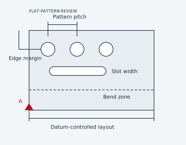
Define hole size, pitch and edge margin from the same datum system. The schematic identifies review points; dimensions come from your drawing.
Hole size & tool guidance
A small hole relative to sheet thickness increases demands on the punch. The workable ratio varies with alloy, strength, tool guidance and maintenance; do not apply one minimum diameter across all materials.
Hole spacing & edge margin
Narrow webs and small edge distances can distort or tear. As an initial design reference, Mate recommends a clear distance of at least twice the sheet thickness between holes and between a hole and a sheet edge. Confirm the actual geometry and tooling before adopting that guideline.
Holes near bends
Keep critical openings out of the bend deformation zone where practical. Define the inside radius, bend line and finished hole position; a flat-pattern dimension alone may not control the location after bending.
Clearance, cut edge & burr
Punch-to-die clearance changes the rollover, burnished band, fracture and exit burr. Specify the functional hole size, permitted edge break and burr side. Do not treat a sheared hole as a machined cylindrical bore.
Dense patterns & flatness
Repeated cutting can distort a panel. Pattern layout, open area and the cutting sequence need review together with the measurement method. Define flatness in the finished condition and identify any support or clamping conditions.
Engineering reference: Mate hole-design guidance ↗. These are design considerations, not unconditional production limits.
Carry the hole requirements through the next operation.
Include every operation needed for the delivered part in your RFQ. Sequence and access matter: a correct flat hole can become an incorrect mounting interface after forming or coating.
Deburring & edge treatment
Identify hand-contact edges, cable openings and sealing surfaces. Specify burr removal, edge break and the permitted effect on small holes or thin webs. A blanket “no sharp edges” note may need a measurable acceptance definition.
Bending & hardware
Supply the formed model, bend datums and hardware callouts. Check tool access, insertion direction and the effect on local flatness. Confirm whether critical dimensions apply before or after assembly.
Welding & assembly
Define mating parts, weld locations and fit-up. Review weld distortion, hole alignment and access for fasteners. Specify the delivered subassembly and any functional checks.
Coatings & cosmetic surfaces
State the finish system, coating thickness and masking. Coating can reduce usable hole or slot clearance. Mark appearance zones, handling requirements and any reference samples in the acceptance plan.
Special features need a defined route.
Louvers, embossing, extruded holes, tapping and nibbling depend on dedicated tools and process compatibility. Identify them explicitly in your inquiry. CNC or turret tooling and special forming features are confirmed for the project rather than assumed from the part name.
Inspect what makes the part fit.
Set acceptance around function. Define critical features, measurement datums and the state of the delivered part before production begins.
Material & revision
Identify the approved drawing revision, material grade, thickness and finish. Request material documentation where required and agree its scope in the quotation.
Hole & pattern geometry
Call out critical diameters, slot widths, pitch and true position where needed. Specify a datum scheme, rather than accumulating dimensions across a long pattern.
Edges & flatness
Define burr direction and height criteria, edge treatment, panel flatness and cosmetic limits. State whether the checks apply after deburring, forming or coating.
First article & records
Request first-article samples, dimensional records or other documents when needed. Agree sampling, inspection methods and any functional gauge before the order. Reports and testing follow the accepted project scope.
Punching questions,
answered.
From route selection to the drawing package.
What is sheet metal punching?
Sheet metal punching uses a punch and die to shear holes, slots or repeated openings in sheet. In piercing, the surrounding sheet is the part and the removed slug is scrap. In blanking, the cut-out blank is the useful part. A single component can require both operations.
Is punching a good choice for my panel?
Repeated hole shapes and patterns are good reasons to evaluate punching. Tool availability, the number of hits, material strength, edge requirements and quantity determine the route. Laser cutting may suit changing contours or features that would need special tooling. Compare the complete finished part, including deburring and forming.
Do you use CNC turret punching for every order?
The production route is selected for the drawing and quantity. If CNC turret punching, nibbling, louvers, embossing, extruded holes or in-process tapping are required, identify them in your inquiry so the tooling and route can be confirmed in the quotation. These operations are not interchangeable with a simple pierced hole.
What are your minimum hole size, sheet thickness and tolerances?
There is no single limit that applies to all materials and parts. Small holes depend on sheet thickness and strength, punch guidance, tool condition and geometry. Specify your exact grade, thickness and critical dimensions. The accepted drawing and quotation define the achievable features and inspection requirements for your order.
Will punched holes be free of burrs and distortion?
Punching can leave rollover, a burnished zone, a fracture zone and an exit-side burr. Dense patterns can distort the sheet even though the cut is mechanical. Specify burr direction, edge break and flatness requirements, and whether inspection applies before or after deburring, bending and finishing.
Can you include bending, hardware and surface finishing?
Include the finished-part requirements in your inquiry. Bend sequence, hardware insertion, welding, coating and masking can change hole geometry or access. Confirm the operations, materials and final acceptance requirements together in the project quotation.
How are tooling, quantity and repeat orders quoted?
Tool availability, special tool development, setup, hit count, material utilization and secondary work affect the quotation. Send initial quantity, quantity breaks and annual demand. For dedicated tooling, agree ownership, maintenance, revision handling and repeat-order expectations before committing.
Which files should I send for a punching quote?
Send a DXF flat pattern and a dimensioned 2D drawing, plus a STEP model for formed parts when available. Include units, revision, material grade and thickness, datums, critical hole locations, burr and cosmetic requirements, quantity, finishes, inspection documents and destination. The quote page lists DXF, STEP/STP and PDF among its common formats.
YOUR NEXT COMPONENT
Bring the drawing.
Define the finished part.
Send the flat pattern, formed geometry and acceptance requirements. Include your first order and annual demand so the quotation can address tooling, production and secondary operations together.
Your drawings stay confidential. Optional NDA available ↗
Your punching RFQ checklist
- Geometry & revisionDXF flat pattern, STEP model and dimensioned 2D PDF; units and revision.
- Material & thicknessExact grade, temper or condition, sheet thickness and any coating.
- Features & acceptanceHole and array datums, critical tolerances, burr side, edge treatment, flatness and appearance.
- Finished componentBends, hardware, welds, finish, masking and assembly fit requirements.
- Order & deliveryQuantity breaks, annual demand, inspection records, packaging and destination.