GD & T datum
Technical drawings communicate, but for someone who is not familiar with them, they can be confusing. The symbols and boxes within the drawings are some of the most misunderstood. They represent the Geometric Dimensioning and Tolerancing system, which relies on datum, another critical concept.
In manufacturing, CNC machining and other techniques provide invaluable solutions. Manufacturing parts is more technical than it appears because the work doesn’t stop at getting the right size of a part. Knowing where specific measurements should begin is equally essential, hence the need for GD&T datums.
These are valuable reference points, lines, and planes upon which measurement accuracy is based. Working without GD&T datums means relying on guesswork, which can be disastrous.
There is a lot about GD&T datums, including classifications, measurements, and simulations, all of which have been covered in the article. The classification of datums by geometry and function has been explained too.
GD&T datums are powerful tools, aiding in CNC machining services and quality assurance, thus making moden machining highly reliable for different industries.
Continue reading this guide on GD&T datum as we go through the basics of the concept and how it contributes to quality manufacturing.
What Is A Datum?
Types of datum
So, what exactly is a datum? A datum is a reference line, plane or point. Users refer to this point for subsequent measurements. Consider a metal that should have a hole drilled on one face. You can measure the location of the hole from any side, but without a reference, it is difficult to communicate or even drill a similar hole in a similar metal block.
The situation is very different if you mark one corner of the block as the datum or reference point. With measurements taken from this corner, accuracy and precision is easily achieved.
What Is A Datum In GD&T?
What about Geometric Dimensioning and Tolerancing (GD&T) datum? This is a standardized reference applied in a GD&T system. ASME Y14.5 is a good example of a GD&T system used at ProleanTech, which is characterized by specified symbols, Feature Control Frames (FCFs), and tolerance zones among other features.
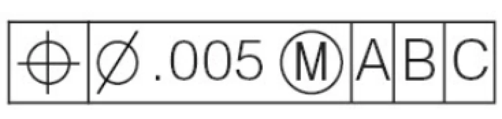
A feature control frame (FCF)
Other related standards are ASME B89.3.1-2021 and ISO 1101:2017.
In case you are wondering about gd&t definition, this is a common language used by designers, engineers, and manufacturers to define and communicate nominal dimensions and geometric tolerance in manufactured parts. This symbolic language applies for both engineering drawings and computer based 3-D models.
The system is more like a complementary system to the standard dimensions; not a replacement. It works in tandem with the dimensions to provide a more detailed picture that includes not only the ideal geometry of a part but also its tolerance.
Why GD&T Datums Matter In Engineering
For engineers and machinists, a datum is a significant element that helps measure, place, and manufacture parts accurately. It is a tool for controlling component or part geometry.
First, GD&T datums provide a repeatable platform for measurement reference no matter the person involved in the task. The time of taking the measurements also does not matter. By minimizing variations of measurements, the datums guarantee the consistency and order of part features.
The second datum matters because of the requirement for parts to fit together as designed. In the absence of data, parts can easily be misaligned and end up performing below expectation.
With the third datum, the machining process is devoid of tolerance challenges. The problem of confusion caused by many deviations is prevented.
Further, GD&T makes sense to the CNC quality control team. The team uses this as reference to check if a part complies with design requirements. A perfect example of a tool used by the team that is based on datum points is the Coordinate Measuring Machine (CMMs).
In summary, here are the benefits of GD&T datum:
- Ensures predictable part positioning and orientation in different inspection and manufacturing setups
- Reduces confusion in technical datum drawings, enhancing interpretation accuracy
- Simplifies fixture design through identifiable reference points and surfaces
- Enables easy measurements through coordinate measuring machines (CMMs)
Try Prolean Now!
Types And Classifications Of GD&T Datums
There are two popular categorizations of GD&T datums: In terms of function and geometry. Looking at the function angle, GD&T datums are available in sequential types namely primary, secondary, and tertiary datum. Each of these has a level of constraint on the machined part.
The second classification has a geometry focus and covers point datum, line datum, and plane datum.
As a part end user or reseller, you should understand how these classes correlate and apply so that they can always meet assembly and functional requirements.
Types Of Datum Based On Function
Types of datum
Primary Datum (A)
This datum forms the basis for performing the other measurements. It is the most preferable for machinists and engineers. The most notable requirement is the constraint of at least one degree of freedom. Others are translational and rotational movements.
Secondary Datum (B)
The secondary datum comes in for more complex parts. The point is referenced to the primary datum with the aim of constraining the degrees of freedom even further. It relies on at least two contact points on the machined part.
Tertiary Datum (C)
This datum is necessary for a tighter constraint on the part or component. This point is essential in eliminating the third degree of freedom. That means with this one, no rotation or movement remains. The point of contact is most likely a corner.
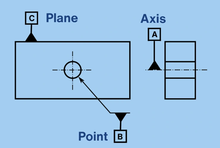
Types Of Datum Based On Geometry
When it comes to geometry, other three types of datums emerge in the form of point, line, and plane datums.
Point Datum
A point datum shows the location of a specific point on a part, which is effective in controlling one degree of freedom.
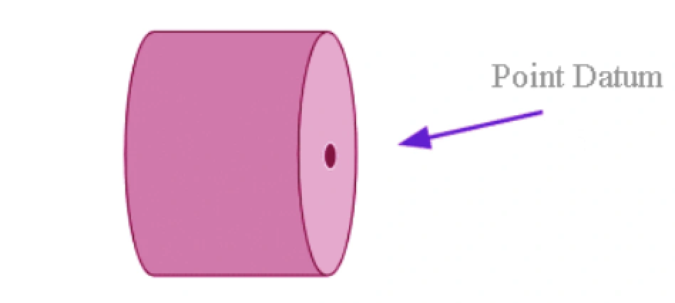
Point datum
Line Datum
This type of datum defines a line’s position on a part or component surface. It eliminates two degrees of freedom.
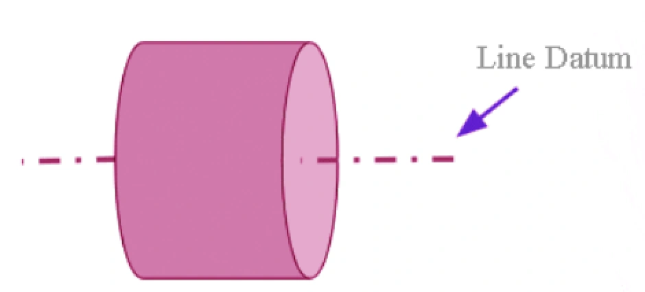
Line datum
Plane Datum
The function of the plane datum is to point to a plane position on a part’s or component’s surface. This type of gd&t datum eliminates three degrees of freedom.
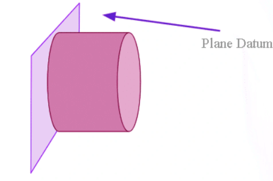
Plane datum
How Is Datum Calculated?
The calculation of gd&t datums is based on the derivation of theoretical points or axes from a real part. For repeatability of the process, these points are taken on holes or flat surfaces that can be easily used in inspection or manufacturing.
Here is a summarized five-step process of calculating datum:
Step 1: Establishing The Datum Features
From the datum drawing, check and locate the datum features, which are normally indicated as A, B, and C.
Step 2: Stabilizing The Part On The Primary Datum
Use a coordinate-measuring machine (CMM) or fixture to simulate the primary datum. This entails restraining three degrees of freedom by contacting three points.
A coordinate measuring machine (CMM)
Step 3: Aligning The Part To The Secondary Datum
The next step is to establish the secondary datum, B, which prevents side to side movement of the part and one rotation. Here, two contact points are involved.
Step 4: Locating The Tertiary Datum
To locate the tertiary datum, C, you need to contact a point on this plane, which should restrain the remaining rotation.
Step 5: Measuring Features In Relation To The DRF
We have now established the Datum Reference Frame and can use it as reference for feature measurements.
Concerning simulation of gd&t datums, CMM probes, V-blocks and such tools come into play. The idea is to have these tools “contact” high points on the datum features. This is how the Datum Reference Frames (DRFs) are defined.
With this, the manufacturer can easily and repeatedly measure features related to CNC precision machining regardless of the number of parts presented.
What Is The 3 2 1 Rule For Datum?
The 321 rule for datum refers to a popular method for simulating a datum based on the constraint of the part’s movement. The numbers represent contact points as follows;
3 – Three contact points on the primary datum that restrict the part to three degrees of freedom.
2 – This is for the secondary datum that restricts the part to two degrees of freedom.
1 – Refers to the tertiary datum and the restriction of the part to one degree of freedom.
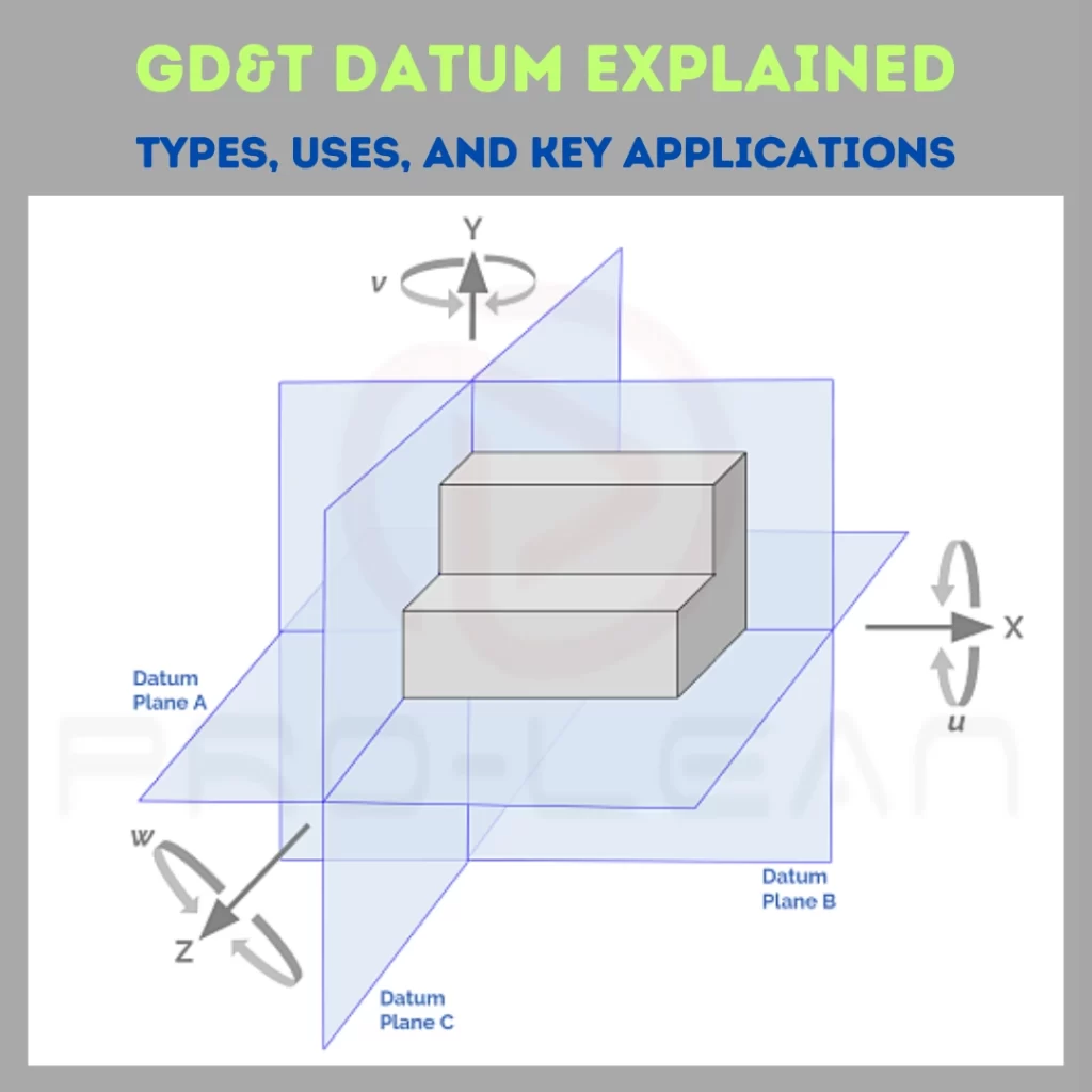
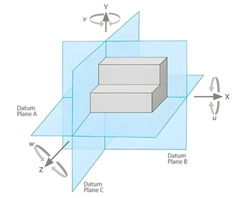
Datum Reference Frame (DRF) Explained
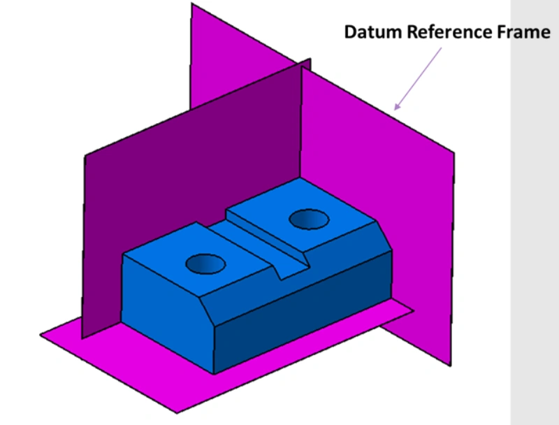
Datum reference frame
The Datum Reference Frame (DRF), which we mentioned a little earlier, is made from the primary, secondary, and tertiary datums and comprises three planes. This coordinate system systematically eliminates the six degrees of freedom, thereby forming the fundamentals of machining, measurements, and assembly.
With the DRF, a part’s geometric dimensions and tolerances can be easily defined. Without the system, it is impossible to define a part clearly, and subsequently, its inspection outcomes are unpredictable.
Try Prolean Now!
How to Create the Datum Reference Frame (DRF)
To understand the DRF better, let’s see how to create one.
- Select Datum A, which is typically the most important and stable surface. It can be a mounting face or flat flace that restrains three degrees of freedom.
- Select Datum B, which often is the surface that is a perpendicular reference for Datum A. Datum B restricts another two degrees of freedom (translation on Y and rotation around Z)
- Select the tertiary Datum, also known as Datum C. The function of this datum is to remove the remaining degree of freedom. It can be a point or another perpendicular plane that effectively locks the part into position by eliminating translation along X.
The created datum reference frame is consistent and a basis for accurate measurement and alignment in assemblies, complex or not. Establishing a good DRF can significantly improve manufacturing quality and reduce errors.
Datum Symbol Classification
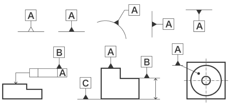
Datum symbols
The datum symbol classification in GD&T concerns the different ways of identifying datum features on a technical drawing. While a symbol datum typically comprises a capital letter within a rectangular frame, it is important to recognize the different classifications – datum feature, datum reference, datum target, and datum point symbols.
Datum Feature Symbol
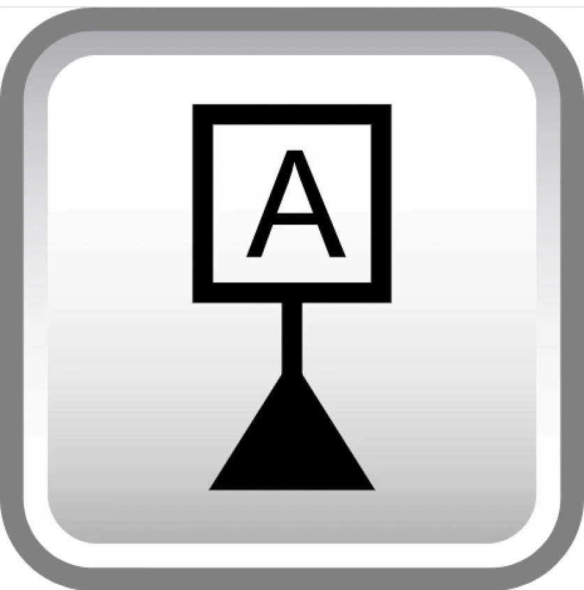
Datum feature symbol
The feature symbol entails a square frame containing a capital letter. It connects to the feature via a leader line.
Datum Point Symbol

Datum point symbol
In technical drawings, point symbols are either dots or crosses, which indicate special reference points.
Datum Reference Symbol
This symbol is shown by capital letters within a frame – circular, square, or triangular.
Datum Target Symbol
The datum target symbol is a classification entailing a horizontally segmented circle. The upper segment of the circle is left empty for lines and points while the lower segment carries the sequential number and datum letter.
Applications of GD&T Datums
GD&T datums help measure, position, and assemble parts throughout the manufacturing and inspection process. Popular applications of these references are CNC programming, tolerancing, and fixture design.
GD&T Datum In CNC Programming
Like CNC machining designers, programmers must understand the pivotal role of GD&T datums. They then can use these references when defining toolpaths and cutting strategies. On strategies, CNC programming may require adjusting feed rates and cutting speeds according to recommended form control.
GD&T Datum In Tolerance Analysis
Tolerance analysis, which entails the determination of the shape and size variations allowed for a part, uses GD&T datums. Individual components in an assembly have variances that add up to larger variances.
If not well managed, the total variance can have adverse effects on the assembly’s functionality. Through tolerance analysis based on GD&T datums, the designer can realize effective cumulative variations that do not significantly affect the component’s functionality.
GD&T Datum In Fixture Design
Effective fixture design has several requirements, including ensuring accurate work clamping during the CNC machining process as referenced in the technical drawing. In other words, the primary, secondary, and tertiary datums on the fixture should restrict the part being machined the same way all the time.
More reading: CNC Machining Complete Guide
Conclusion
GD&T plays the critical function of defining parts in manufacturing processes. With the concept of GD&T for datums, engineers are able to create coordinate systems that lay the foundation for manufacturing features on subsequent parts.
Simply put, GD&T datums ensure parts are made with the correct fit and function. Therefore, it is valuable for all involved in parts manufacture and specification to understand how GD&T works and its effects on parts’ quality.
ProleanTech relies on accurate precision datum systems that guarantee the best CNC machined parts. Our insistence on measurement accuracy is the reason our parts always exceed customer expectations in aerospace, medical, automotive, and many other industries.
You can contact us now to learn more about this concept and how it aligns with your CNC machining goals


0 Comments