
Laser cutting
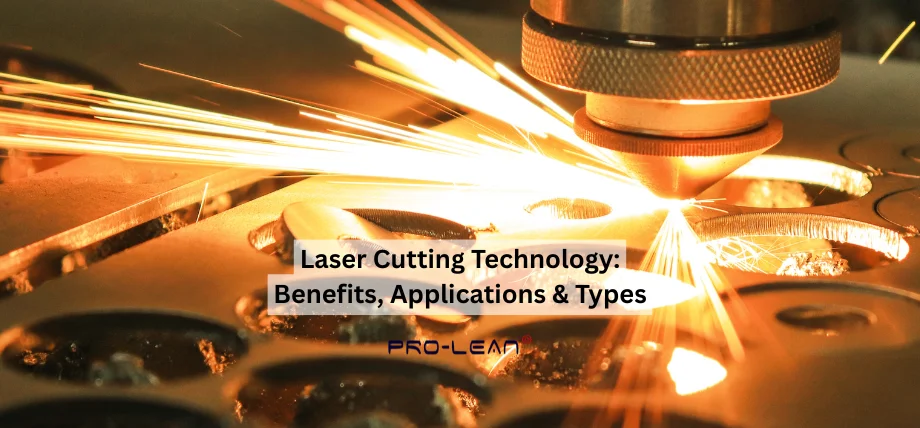
Laser cutting process uses a concentrated high-energy laser beam to cut materials by melting or vaporizing them, which results in exact cuts that cause minimal damage to the workpiece, showing advanced laser cutting technology.
Proleantech provides high-quality laser cutting service for precision parts, sheet metal parts, and provides cutting for materials sensitive to HAZ. Using technology, including plasma cutting, fiber lasers, and no-contact laser cutting process methods, you can get accurate parts and optimized production runs for kerf widths and minimal burrs with precision cutting technologies.
Introduction to Laser Cutting Technology
The laser cutting process uses a focused infrared light beam, which passes through optical components to create material separation through power densities that reach 10⁶ W/cm², demonstrating how laser cutting technology works in both fiber laser vs CO2 laser. The system combines computer numerical control (CNC) for path guidance to produce intricate shapes with narrow 0.1 mm kerf widths and precise tolerances down to ±0.025 mm in industrial applications.
What Is Laser Cutting?
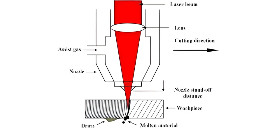
Laser cutting technology uses a powerful laser beam to heat workpieces until they reach their melting or vaporization points. The assist gas jet operates in the same axis as the beam to push out molten and vaporized material, which creates the kerf.
The process starts when photons enter the material to create heat spots that transform the material through a phase transition. Material removal occurs through four main modes: fusion cutting (inert gas), reactive fusion cutting (oxygen), vaporization cutting, and controlled fracture/ablation for brittle or heat-sensitive materials. The beam focusing system produces spots between 0.1 mm and 0.5 mm in diameter, which generate enough power density to create instant vaporization during pulsed operations.
Laser Cutting Components
Laser Source
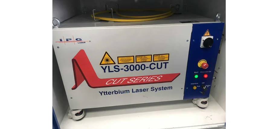
Laser System Unit
The resonator produces the beam through stimulated emission, which occurs in the gain medium, consisting of gas, solid-state crystal, or fiber materials.
Beam Delivery System
The beam delivery system uses mirrors and fiber optics to transmit the beam while preserving its quality through M² factor values below 1.3 for single-mode operation.
Focusing Optics
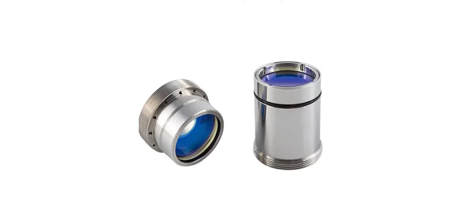
Laser Focusing Lenses
The system utilises lenses or adaptive mirrors to achieve diffraction-limited spot formation, operating at focal lengths ranging from 50 to 200 mm for sheet metal applications.
Cutting Head
The cutting head features a 0.8–3 mm diameter nozzle, along with capacitive or optical height sensors for standoff control with a precision of 10 µm, and an assist gas entry point.
Motion System
The gantry, hybrid, and flying optics configurations enable users to achieve 10 µm positioning accuracy during movements across 6 m × 3 m travel areas.
CNC Controller
The system reads G-code commands while controlling laser frequency modulation between CW and pulsed modes at MHz rates and handling all process settings.
Assist Gas Supply
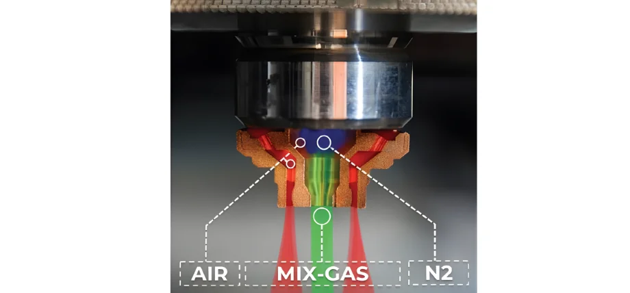
Assist Gas Nozzle Diagram
The system operates with high-purity nitrogen (99.999%), oxygen, and argon at pressures ranging from 5 to 25 bar.
Chiller and Exhaust
The system maintains temperature stability while extracting all fumes and particles from the system.
Try Prolean Now!
Laser Cutting Mechanism
The main removal processes occur through:
- Melt expulsion: The process of liquid phase removal through shear forces from supersonic gas jets is dominant in metal materials.
- Vaporization: The process needs more energy than the latent heat of vaporization to occur, which makes it suitable for thin materials and refractory substances.
- Chemical degradation/ablation: The breakdown of chemical bonds and photochemical reactions occurs in polymer and composite materials during their degradation process.
- Phase explosion: The process of phase explosion occurs when ultrashort-pulse irradiation creates superheated liquids that explosively transform into vapor and plasma states.
Laser Cutting Process
Design Preparation and CNC
Laser cutting begins by converting CAD models into 2D or 2.5D vector paths using CAM software. The system uses nesting algorithms to optimize material usage while adding lead-in and lead-out sections and micro-joints, and overcuts to protect corner areas from defects and maintain part attachment to the skeleton.
Workpiece Fixturing
The workpiece gets secured by vacuum or mechanical clamps, which support the material while allowing reflections and dross to drop through. The cutting head standoff requires calibration before commencing work, while also checking the nozzle condition. Sheet or plate rests on a honeycomb or pin, or a slat bed, which supports the material while blocking.
Piercing
A controlled high-peak-power pulse or power ramp produces a through-hole at the starting point. The duration of the process spans from 0.3 seconds for thin materials to 15 seconds for 25 mm stainless steel sheets. Spiral and wiggle motion patterns help prevent nozzle damage from ejected material. Piercing parameters differ from cutting parameters due to higher melt volume. The parameters used for piercing operations differ from those used for cutting operations because they produce excessive melt volume.
Contour Cutting
The motion system reaches its programmed feed rates, which range from 10 to 150 m/min for processing thin metal materials. The laser power adjusts instantly with speed changes to maintain a constant energy level (J/mm). The system maintains optimal focal position, gas pressure, and pulse parameters for specific material thicknesses, achieving kerf widths between 0.1 and 0.5 mm and surface roughness below 5 µm.
Assist Gas Application
The nozzle directs high-pressure gas between 5 and 25 bar to create a supersonic jet, which cuts through molten material by pushing it downward. The use of nitrogen or argon gas creates oxide-free edges when cutting stainless steel, aluminum, and titanium. In contrast, the reaction between oxygen gas and carbon steel leads to an exothermic reaction that boosts cutting speed by 100–300% for thicker cuts at constant power levels.
Types of Laser Cutting Machines
|
Parameter |
Fiber Laser |
CO₂ Laser |
Nd:YAG / Pulsed Nd:YAG |
Direct Diode Laser |
|
Wavelength |
1.07 µm |
10.6 µm |
1.064 µm |
0.9–1.0 µm (blue 450 nm) |
|
Gain Medium |
Yb-doped fiber |
CO₂/N₂/He gas mix |
Nd-doped crystal |
Semiconductor diodes |
|
Wall-Plug Efficiency |
30–50% |
10–20% |
20–30% (diode-pumped) |
40–60% |
|
Beam Quality (M²) |
1.1–2.0 (single-mode) |
1.2–1.5 |
1.3–50 |
10–100 |
|
Typical Power Range |
500 W -100 kW+ |
1–30 kW |
50 W–8 kW |
2–30 kW |
|
Primary Materials |
Metals (incl. highly reflective) |
Non-metals, thick carbon steel |
Metals, ceramics, drilling |
Thin metals, copper/brass |
|
Cutting Speed (1 mm SS) |
Highest (>100 m/min) |
Moderate |
Lower |
High on thin sheets |
|
Maintenance |
Very low (>100,000 h) |
Moderate (gas) |
Moderate–high |
Very low |
|
Capital Cost (6 kW) |
Medium–high |
Low–medium |
High |
Medium |
Fiber Laser Systems
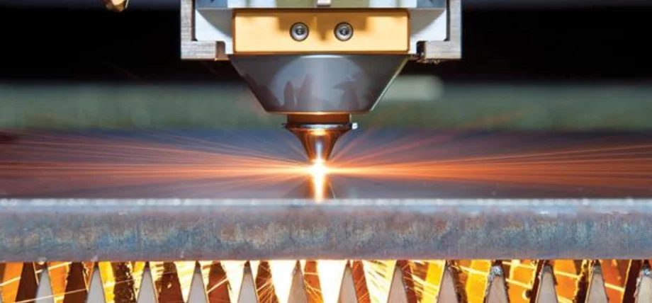
Laser Cutting Thick Metal
The gain medium of fiber lasers consists of ytterbium-doped silica fibers, which generate 1.07 µm wavelengths while achieving wall-plug efficiencies between 30% and 50%. The delivery of beams happens through flexible fiber optics, which eliminates the need for moving mirrors in flying-optics systems. The single-mode fibers produce M² values below 1.3, which allows them to create spots smaller than 25 µm while achieving cutting speeds above 100 m/min on 1 mm stainless steel. The near-IR wavelength absorption of reflective metals such as copper and brass makes these lasers the top choice for modern flatbed cutting applications, which hold a large share of the high-power market.
CO₂ Laser Systems
Laser Cutting Process Diagram
The CO₂ lasers operate at 10.6 µm through gas discharge in a CO₂-N₂-He mixture, which has been the traditional choice for industrial cutting applications. The delivery of the beam requires articulated mirrors, which can become misaligned. The system produces high-quality beams (M² ≈1) with strong far-IR absorption and on thick carbon steel when using oxygen as an assist gas. While achieving excellent results on non-metallic materials (acrylic, wood, textiles), the system operates at 10 – 20% efficiency, requiring additional expenses for gas usage and mirror maintenance.
Nd:YAG and Nd: YAG Pulsed Laser
Nd:YAG Laser Diagram
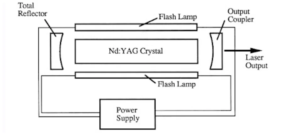
Nd: YAG rod or disk lasers that contain neodymium doping produce light at 1.064 µm wavelength. The development of diode-pumped lasers has made lamp-pumped versions obsolete. The high-peak-power requirements of drilling and thin-metal trepanning operations can be met through pulsed operation at ms time scales. The beam quality of these lasers spans from M² 1.3 to 20, while fiber-coupled delivery allows robotic arm operation. The main application of these lasers involves spot welding and fine cutting of ceramics and reflective alloys when fiber power does not suffice.
Direct Diode Lasers
Direct diode lasers operate by uniting multiple semiconductor emitters directly without any intermediate amplification stage, which results in improved efficiency. The beam quality of these lasers remains poor because they produce M² values between 10 and 100, which restricts their ability to focus and maintain thin kerf widths. Direct diode lasers operate as a compact, robust, and affordable solution for high-speed processing of thin sheets less than 6 mm thick, performing well in cutting, cladding, and heat treatment applications. The development of blue-diode variants at 450 nm has led to significant improvements in copper absorption rates.
Try Prolean Now!
Laser Cutting vs Water Jet Cutting
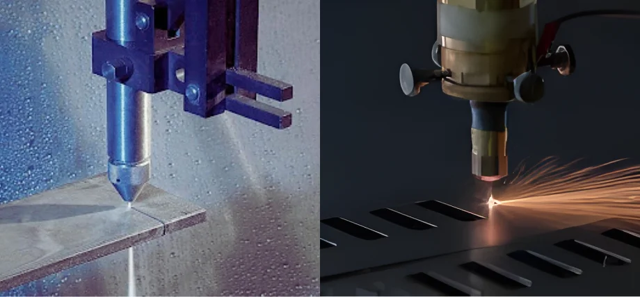
CO2 vs Fiber Laser Cutting
The process of abrasive waterjet cutting uses high-pressure water streams containing garnet particles, which travel at 6,200 bar through jewel nozzles to remove materials through mechanical erosion. Laser cutting technology offers faster processing, tighter tolerances, and narrower kerfs for materials under 25 mm. However, waterjet cutting becomes necessary when thermal effects must be completely eliminated.
- Advantages of laser cutting: Laser cutting process provides five to twenty times faster metal cutting speeds for materials under 15 mm thickness and is ideal for titanium laser cutting and laser cut carbon fiber, while producing a 0.1–0.5 mm kerf that is narrower than the 0.8 – 1.5 mm kerf of waterjet cutting. The process operates at lower costs for thin to medium-gauge materials, eliminating the need for abrasive materials and delivering precise tolerances of ±0.025 mm.
- Advantages of waterjet cutting: Waterjet cutting offers two primary benefits to users: it eliminates heat damage to materials and allows users to cut thick materials, such as titanium, up to 300 mm thick, while protecting sensitive materials from burning or cracking.
Laser Cutting vs Mechanical Cutting
The cutting process, performed through mechanical methods, includes plasma arc cutting, oxy-fuel cutting, and punching and milling operations. It also includes wire EDM vs laser cutting. Laser cutting delivers exceptional edge quality while handling a wide range of materials, from thin to thick sheets, up to 50 mm in thickness, at economical costs.
Advantages of laser:
- Narrow kerf (0.1–0.5 mm)
- High surface finish (Ra <5 µm)
- Small HAZ (<100 µm in fiber systems)
- No tool wear
- Able to cut reflective & non-conductive materials
Advantages of mechanical methods:
- Cost-effective for thick carbon steel (>50 mm)
- Punching is ideal for fast hole production in ductile metals (<15 mm)
- Milling supports 3D shaping when laser absorption is poor
Applications of Laser Cutting
Aerospace
The aerospace manufacturing industry depends on laser cutting technology because it enables precise operations that maintain both material quality and exact dimensions. The process creates cooling holes between 0.2 mm and 0.8 mm in nickel superalloys for turbine blades and generates honeycomb seal structures and composite skin trimmings. The cutting process of composites benefits from UV and picosecond lasers because they create clean cuts without delamination.
Automotive
The automotive industry depends on laser cutting technology for the precise mass production of its components. The process enables manufacturers to cut hydroformed tubes and slit thin copper and aluminum battery foils down to 50 µm thickness and create body-in-white components from high-strength steels with reduced distortion.
Electronics
The production of electronics depends on precision laser cutting to create small features. The process uses laser technology to create PCB stencils and flexible circuits and to separate silicon wafers. The current technology allows users to achieve edge chipping below 5 µm, which supports the development of smaller devices.
Medical Devices
The process of laser cutting allows manufacturers to produce intricate medical components at a small scale. The process allows manufacturers to produce Nitinol stent struts with widths between 50–200 µm and create intricate designs on catheter hypotubes and surface textures for orthopedic implants to enhance bone attachment.
Factors to Consider for Laser Cut Quality
- Power & mode: High power increases kerf/HAZ; pulsed mode reduces thermal load.
- For optimal results, operators should maintain the correct speed, as this method produces smooth edges and minimal dross formation.
- Selection of assist gas between nitrogen and oxygen determines edge quality, while oxygen gas increases cutting speed for carbon steel but expands the heat-affected zone.
- The surface focus position produces minimal taper, while negative focus helps decrease bottom dross formation.
- Optimal standoff distance between 0.5 mm and 1.5 mm maintains proper gas flow direction.
- Laser cutting of reflective alloys needs fiber/Nd: YAG lasers because of their properties, while thicker materials need increased power levels and oxygen flow.
- Laser cutting benefits from circular polarization because it produces equal surface roughness in all directions.
- Laser cutting process achieves better results through high-frequency low-energy pulse patterns, which minimize the formation of recast layers.
Try Prolean Now!
Custom Laser Cutting Service
Get high-quality laser cutting and machining service with high precision, speed, and consistent part production. Proleantech has advanced equipment that supports custom laser cutting for metals, plastics, and composites.
Get an online quote today and experience exceptional edge and kerf quality with minimal material distortion for your parts.
Conclusion
The laser cutting technology provides exceptional precision and fast operation with wide material compatibility, including laser cut carbon fiber, through fiber sources, which power most industrial applications because they deliver high efficiency and excellent beam quality, and understanding how does a laser cutter work. The selection of appropriate parameters leads to reduced HAZ formation, dross generation, and surface roughness for applications that need strict engineering standards.
FAQ
How Does a Laser Cutter Work?
A laser cutter focuses a high-energy beam onto material to melt or vaporize it along a programmed path, while a coaxial gas jet removes debris to produce a thin kerf that operates under CNC guidance.
0 Comments