
FDM 3D Printing feature image
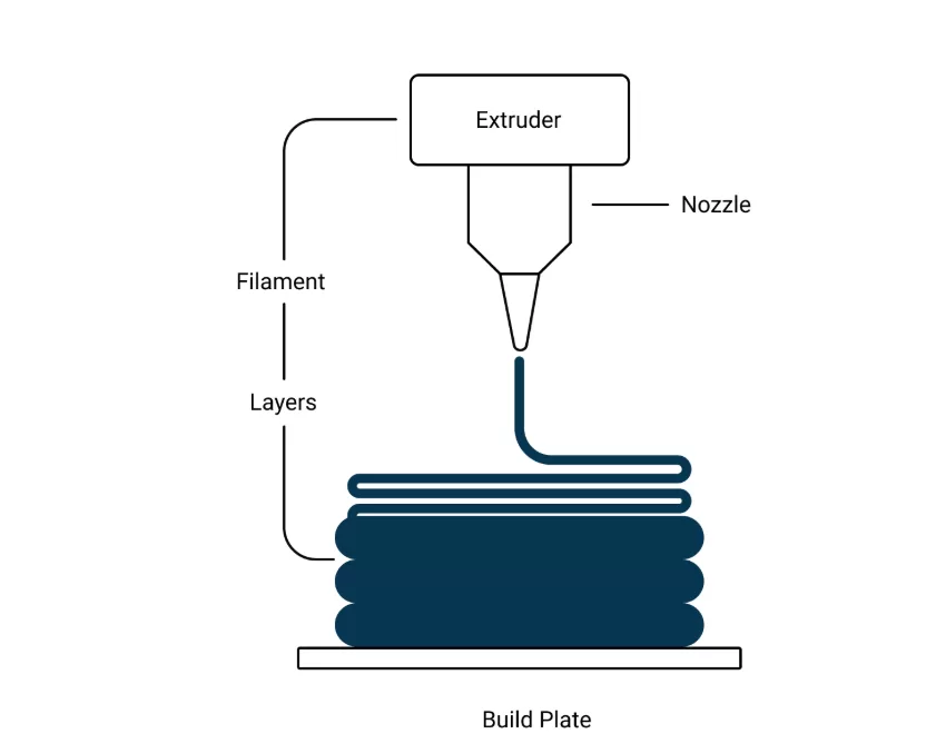
Fused deposition modeling is an additive manufacturing process that builds 3D physical models based on CAD designs. The material filaments are fed through a heated nozzle, which melts the extruded filament and deposits layers one above another on the printer’s build platform.
FDM is the most widely accepted 3D printing method, not only for hobbyists and concept prototyping, but it has also been a prominent manufacturing method for testing prototypes, tooling, education models, jewelry, and other applications.
This article will discuss the fundamentals of FDM 3D printing, its working principle, compatible materials, and industrial applications.
Let’s get started!
Key Takeaways
- In FDM 3D printing, thermoplastic filament is melted and extruded through a heated nozzle. The successive deposited layers bond with each other to form the final part.
- Desktop 3D printers are well-suited to early-stage prototypes and quick design iterations, while industrial FDM is better for larger parts, functional prototypes, tooling, and low-volume runs.
- Layer height, nozzle/bed temperature, print speed, cooling, raster angle, material, and build orientation are critical factors to consider for the FDM 3D printing process.
- Select FDM for rapid prototypes, functional models, tooling, fixtures, enclosures, brackets, and low-volume custom components.
- SLA and SLS are two alternatives to FDM. SLA is more appropriate for small features, thin walls, high detailing, and applications requiring a smoother finish, whereas SLS is used for complex, unsupported functional parts.
FDM 3D Printing Fundamentals
FDM 3D printing fundamentals
FDM 3D printing involves printing the designed models of mechanical parts & products layer by layer, following a predetermined slicing pattern on the 3D printer. It can build complex and intricate geometries, such as sweeping curves, fluid channels, deep corners, wave-like lattices, interlocking joints, and undercuts. The main limitation is the nozzle size, typically 0.4 mm or higher. So, the feature must be larger than the nozzle size.
You can print several thermoplastics with the FDM method, including PLA, ABS, PA, TPU, PEEK, and PEI. Based on the material type, the feeding speed, nozzle, layer height, cooling intensity, and other parameters must be changed. Meanwhile, the print size depends on the 3D printer’s capabilities. Unlike desktop printers, an industrial FDM printer offers 1 x 1 x 1 m of build volume.
How does FDM Printing Work? Mechanism & Steps
Working of the FDM 3D printer
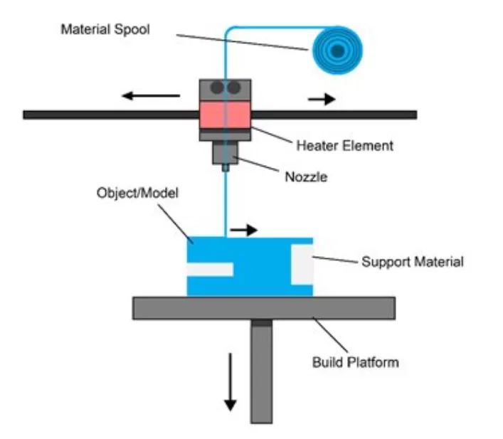
FDM, also called fused filament fabrication (FFF), follows the material-extrusion additive manufacturing mechanism, in which a heating element melts the continuous thermoplastic filament and a nozzle deposits layers. The final shape is obtained via interlayer bond formation.
Let’s break down the FDM 3D printing process.
CAD Model Preparation and Slicing
The first step in the FDM process is preparing a 3D engineering model (.STL or .3MF file) of the desired part/product in design software, such as SolidWorks, CATIA, and AutoCAD.
The next process is the slicing of the design, in which the model is sliced (divided) into thousands of thin horizontal slices (layers), so accurate G-codes can be achieved for nozzle movement, temperature control, and extrusion rate.
Setting Print Parameters for FDM 3D Printer
You need to set different FDM 3D printing parameters, including nozzle temperature, bed temperature, layer height, deposition (print) speed, cooling fan speed, and build orientation, as summarized below.
| Parameter | Typical Range | Influencing factors |
| Layer height | 0.05 to 0.5 mm | Layer height heavily impacts the dimensional accuracy |
| Nozzle Temperature | PLA ~190–220 °C, ABS ~220–260 °C | Depends on the material, raster angle, part type, and other factors. |
| Bed Temperature | Used as a control factor | Depends on the material, thickness, and process response. |
| Raster angle | 0°–90° | It defines the direction of layer deposition (nozzle movement) with respect to the X-axis of the print bed |
Filament Feeding
The roller drive mechanism continuously feeds the filament into the liquefier heating system (extrusion head connected to the nozzle). Meanwhile, the nozzle is also heated to a specified temperature.
Filament Goes into the Liquefier
Using a liquefier mechanism, it melts the solid filaments into a viscous, semi-liquid, or liquid form through an electric cartridge.
Layer Deposition through Nozzle
FDM 3D printing
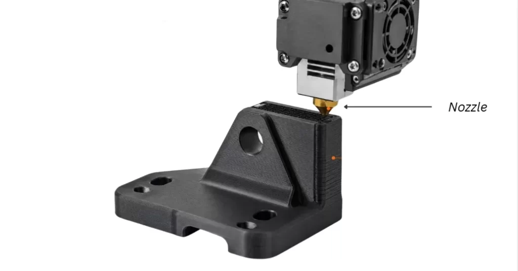
The extruder gear continuously pushes solid filaments, while filament-driven extrusion pressure forces the molten filament through the nozzle, depositing the layer onto the printing bed. The nozzle is permanently fixed to the printer head assembly, which moves along the X, Y, and Z axes (as dictated by the G-codes) and deposits the layer precisely.
Each layer is molecularly interbonded through heat and pressure. Each molecular interdiffusion is the load-bearing bond.
Solidification and Part Removal
Once the built object has cooled to room temperature, it is removed from the build platform. Depending on the print size, removal can be done manually or with a robotic hand. Supports are also detached in this stage. Consequently, the printed parts require trimming and finishing.
Try Prolean Now!
FDM 3D Printing Materials
FDM 3D printing materials
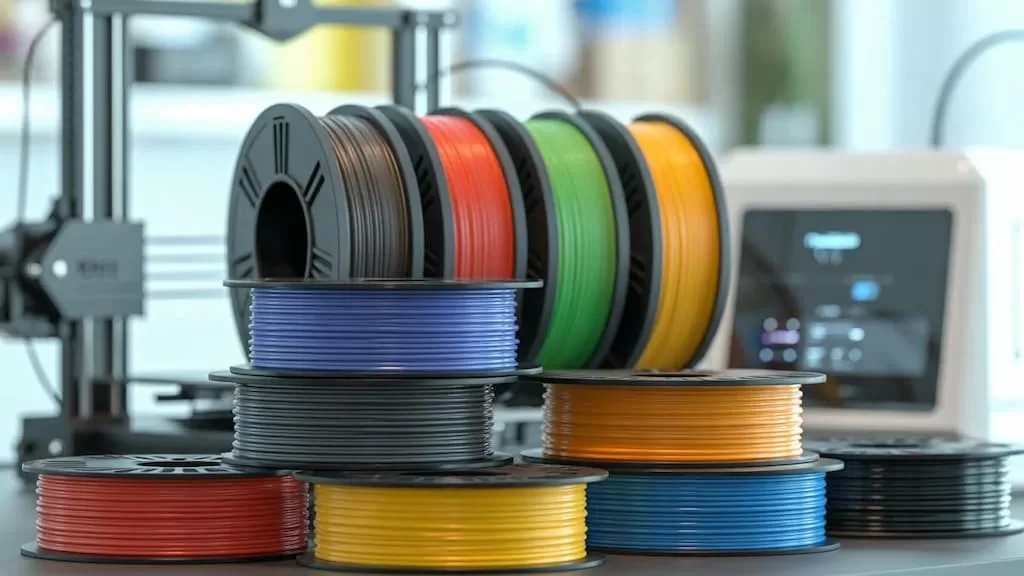
Polylactic Acid (PLA), Polyethylene Terephthalate Glycol (PETG), and Acrylonitrile Butadiene Styrene (ABS) are the most common FDM 3D printing materials. Consequently, PEI, PEEK, PC, and other thermoplastics are also used. You can choose filaments of these materials in the required color and size.
Intended application & functional requirements, operating conditions, desired finish, and 3D printer compatibility mainly govern material selection. PLA provides strength and stiffness, and is suitable for visual prototypes. ABS performs well for outdoor parts, auto parts, enclosures, and functional prototypes. Consequently, PETG is a good alternative to ABS plastic for desktop printers.
| Material | Key benefits | Limitations |
| Polylactic Acid (PLA) | Low warping, easy to 3D print, relatively affordable, and surface detailing. | Lower thermal stability and impact toughness. |
| Polyethylene Terephthalate Glycol (PETG) | Tough, flexible, and moisture-resistant plastic. | Lower thermal stability than polycarbonate, ABS, and a few other thermoplastics. |
| Acrylonitrile Butadiene Styrene (ABS) | Biocompatible grades (e.g., ABS-M30i) are available, tougher than PLA, and have good thermal resistance. | Emits strong fumes during printing and poses a warping risk. |
| Polyetherimide (PEI / ULTEM) | Excellent thermal resistance, high strength, and chemical resistance | Higher glass transition temperature and costly raw materials |
| Polyether Ether Ketone (PEEK) | Biocompatible grades and high mechanical strength. | High processing temperature |
| Polycarbonate (PC) | Impact strength, dimensional stability, optical clarity, and electrical insulation. | Hygroscopic, prone to warping, and high nozzle temperature |
| Nylon | Mechanical strength, toughness, and chemical resistance. | Hygroscopic and requires controlled drying. |
| Thermoplastic Polyurethane (TPU) | Chemical resistance, low friction, and abrasive resistance. | Low printing speed and strict control of process temperatures are required. |
| Reinforced polymers | Excellent stiffness-to-weight ratio, low risk of warping compared to unfilled filaments | Requires heat-treated nozzles and risk of micro-void formation |
Key Considerations for FDM 3D Printing
3D printer selection, minimum wall thickness, feature sizes, post-processing, material warping, and material selection are major considerations for the FDM 3D printing process to ensure accuracy, strength, and built quality.
Desktop Vs Industrial 3D Printers
Desktop 3D printers typically offer a build platform of only 0.2 x 0.2 x 0.2 m, which is suitable for concept models and early proof-of-concept parts. On the other hand, industrial 3D printers are recommended for printing test prototypes, small-scale productions, and functional engineering components.
Optimize Design for Warping
Optimize your design to reduce warping by reducing sharp corners, maintaining uniform wall thickness, and applying stress-relief sections.
Choose Material Carefully
When selecting material for your 3D-printed parts, consider the required functionality, operating environment, ease of printing, and cost.
Minimum Wall Thickness
The minimum wall thickness in FDM 3D printing should be 2–3 times the nozzle diameter.
Consider Surface Finishing
Identify surface roughness level & aesthetic requirements before choosing the finishing technique. Vapor polishing, wet sanding, and epoxy coating are some common options.
Feature Size
The size of the geometrical feature in your design should be larger than the effective resolution limits of the process.
Try Prolean Now!
When to Choose an Industrial FDM 3D Printer over a Desktop 3D Printer?
Desktop 3D printers are for hobbyist projects, small-sized visual models, and concept models. On the other hand, industrial FDM 3D printers offer larger build volumes (~1 x 1 x 1 m), higher precision control & repeatability, the ability to print complex designs, and a wide range of material compatibility.
Choose industrial FDM 3D printing machines for:
- Functional models
- Tooling parts
- Rapid prototypes
- Production runs of custom components in low volume
Choose desktop 3D printers for:
If you are in the early stages of prototype development and want to validate specific features, a desktop printer enables quick iteration cycles.
What Are the Surface Finishing Options for FDM 3D Printed Prototypes?
As FDM 3D-printed items are formed by adding successive layers of material, layer lines and surface roughness are visible on their exterior. Multiple finishing techniques are available to address this issue, such as sandblasting, vapor polishing, painting, and coating.
- Vapor polishing: A vapor stream melts the surface material, forming a thin, uniform, and shiny layer.
- Sandblasting: Sand granules are blasted onto 3D-printed parts, removing surface imperfections and producing a uniform surface.
- Painting: Compatible adhesive paints can be applied for UV protection, aesthetic purposes, and other uses.
- Epoxy Coating: It provides a smooth, durable, and tough surface for 3D-printed prototypes.
What Are the Applications of FDM 3D Printing?
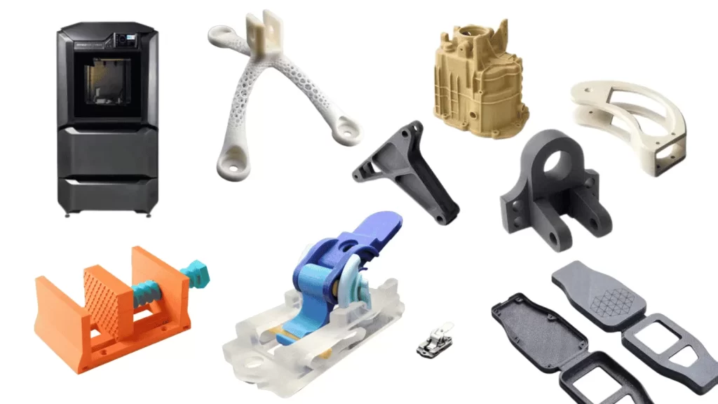
Prototyping with FDM
FDM 3D-printed parts and prototypes are used across industries such as automotive, medical, consumer electronics, tooling, and robotics. FDM is an efficient and cost-effective solution for companies and product developers seeking to build quick prototypes for fit, function, and assembly testing. It can also be used for concept proofs and visual models.
Let’s look at the examples of FDM 3D-printed applications across industries.
- Automotive: Air duct, interior trim, instrument panel, and assembly fixture prototypes.
- Tooling: Testing prototypes for assembly jigs, workholding fixtures, composite molds, and soft jaws.
- Medical: Prosthetic prototypes, anatomical models, and equipment housing.
- Consumer Electronics: Custom enclosures, assembly fixtures, and mounting brackets.
- Robotics: Jigs, fixtures, End-of-Arm Tooling (EOAT), and sensor mounts.
What Are the Advantages of FDM 3D Printing?
- Low installation cost for FDM 3D printers.
- Precise dimensional tolerance, as low as ±0.25 mm
- It enables quick prototypes for engineering designs
- Minimal tooling requirements; no need for cutting tools & molds.
- Faster lead times, as low as 1 day.
- Compatibility with several engineering plastics
- High customization.
- Production of complex, lightweight, and internal features
What Are the Disadvantages of FDM 3D Printing?
- Visible layer lines on the surface, and often, prototypes require post-processing operations.
- The strength of the printed part and the achievable complexity are influenced by the 3D printing material.
- Complex geometry printing requires a support structure, increasing post-processing time and raw material consumption.
- Dimensional tolerances are not as high as CNC machining and injection molding.
Try Prolean Now!
FDM vs SLA vs SLS 3D Printing: What Are the Differences?
SLA and SLS are two different types of 3D printing, besides FDM. Stereolithography (SLA) uses a UV light or laser beam for the selective curing of the resin layer, whereas Selective Laser Sintering (SLS) selectively sinters the polymer powder layer-by-layer to build the designed shape.
Let’s compare these 3D printing methods in compatible materials, complexity, precision, lead time, and cost.
| Parameter | FDM | SLA | SLS |
| Materials | PLA, ABS, PETG, PC, Nylon, TPU, PEI, PEEK, and reinforced polymers. | Various photosensitive liquid thermoset resins | Powdered thermoplastics, including PA11, PA12, TPU, and PP. |
| Complexity | Moderate complexity, requires support structure for internal & intricate features. | Excellent for small-sized features and thin-wall sections | Excellent. The unsintered powder itself supports the printing structure |
| Cost | Lower than SLA and SLS | Moderate | High |
| Precision | ±0.2 to ±0.5 mm | ~±0.025 to ±0.1 mm | ~±0.1 to ±0.3 mm |
| Time | Rapid lead times | Print speed depends on printer architecture, part height, batch layout, and process. | High, when producing prototypes or a batch |
| When to Choose? | Choose low-cost, rapid iteration prototypes, and small-volume runs | Choose when finishing, detailing, and high complexity are required. | For functional mechanical components & prototypes, nylon parts, and unsupported complex prototypes. |
Do You Need FDM 3D Printing Parts and Prototypes?
If you are a design engineer, product developer, startup, or small business looking for testing of your concept and part models, we can print them in our 3D printing facility with rapid lead times and excellent detailing. ProleanTech has experience prototyping complex engineering designs and producing industrial components.
Along with FDM, we offer SLA, SLS, and DMLS 3D Printing Services with flexible iterations and product scaling. Whether you are in the early prototyping phase or need low-volume production runs, ProleanTech can help bring your vision to life.
Our engineers provide a detailed review of designs after assigning the material choice, ease of printing, geometrical complexity, and DFM characteristics, which can help you to decide which 3D printing is best suited for your project.
To start collaborating with us, upload your design file to receive an engineer-reviewed quote. We maintain the confidentiality of each design and specification provided to us.
References
[1] “Basics of Fused Deposition Modelling (FDM),” ResearchGate. ResearchGate – Basics of Fused Deposition Modelling (FDM)
0 Comments