Project overview
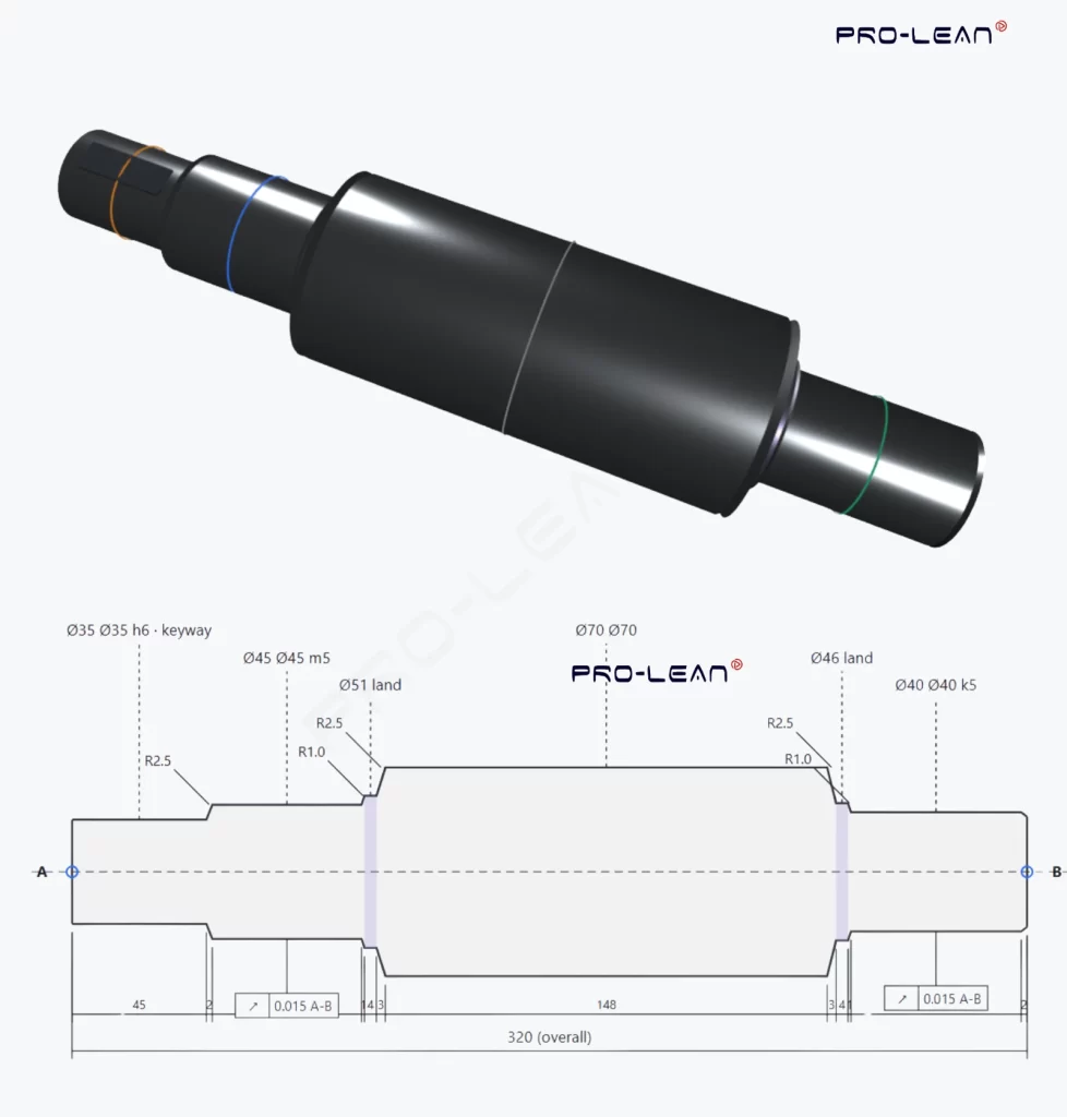
The project brief describes a 320 mm spindle shaft with a maximum Ø70 mm body, a keyed drive section and two bearing seats. It specifies 42CrMo4 alloy steel and a 500-piece batch context.
This engineering case review focuses on the relationship between the drawing, the manufacturing route and the evidence needed to control bearing-seat fit. It does not present an independently verified yield or process-capability result for that batch.
| Design feature | Requirement in the project brief |
|---|---|
| Overall shaft length | 320 mm |
| Maximum body diameter | Ø70 mm |
| First bearing seat | Ø40 k5 |
| Second bearing seat | Ø45 m5 |
| Manufacturing route considered | Turning, heat treatment and final grinding |
DFM: leave access for the final operation
Shoulder geometry has to serve both the bearing and the grinding wheel. A transition radius that improves shaft geometry may interfere with a bearing corner if the available clearance is not considered. A relief or a short shoulder land can provide the required separation.
The project illustration includes Ø51 and Ø46 shoulder lands and clearance-zone fillets near the bearing seats. These features should be evaluated with the actual bearing chamfer, shoulder-support requirement and wheel profile. They are drawing-specific choices, rather than dimensions to copy into every shaft design.
Relief-groove geometry also needs to be defined by the appropriate drawing detail. Naming a relief standard alone is not enough to establish its size, form or suitability for a particular wheel.
Connect heat treatment to finish grinding
A coherent route separates rough turning, heat treatment, datum restoration and final journal grinding. The pre-grind stock must allow the final operation to remove any expected distortion while retaining enough material for the specified finish size.
The workholding arrangement should be defined for each operation. A chuck-and-tailstock setup and a face-driver setup are distinct configurations; their datum and support conditions should not be combined into one ambiguous equipment description.
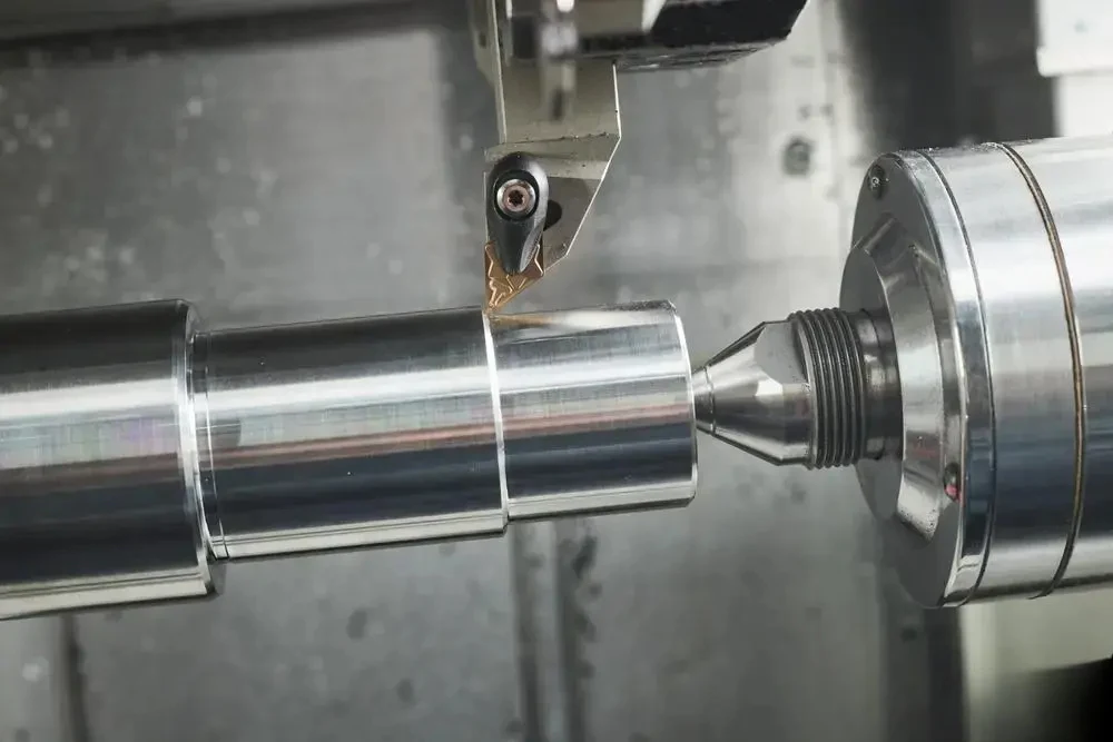
Heat-treatment condition, target hardness, centre-hole preparation and any straightening step should be settled before the finish route is released. The final journal operation then has a clear dimensional and surface-quality task.
Use the correct diameter range for the fit limits
For the over-30-to-50 mm diameter range, the EZO bearing manufacturer’s reference table lists k5 shaft deviations of +2/+13 µm and m5 deviations of +9/+20 µm. Applied to the two seats, these give the reference intervals below.
| Seat | Lower reference size | Upper reference size |
|---|---|---|
| Ø40 k5 | 40.002 mm | 40.013 mm |
| Ø45 m5 | 45.009 mm | 45.020 mm |
These are reference tolerance limits, not measured project results. The released drawing remains the acceptance basis. The resulting bearing fit also depends on the bearing bore tolerance, loading and temperature, not the shaft class in isolation.
A radial shaft tolerance does not independently define axial float. Axial location and thermal movement need to be evaluated through the complete bearing arrangement.
Inspect size, form and process behaviour separately
Journal diameter alone cannot establish the complete functional condition. Roundness, cylindricity, datum-related runout, shoulder orientation and surface roughness need their own drawing requirements and suitable measuring methods.
Statistical control limits answer a different question from specification limits. An individuals chart can help identify a change in process behaviour, but a stable process can still produce parts outside the drawing limits. The chart therefore needs to be read alongside acceptance measurements.
A useful batch-control record connects the measured sequence to the operation, datum, measuring conditions and any intervention. After a correction, verification readings should demonstrate the process condition before production continues. No substitute SPC dataset or capability index is assumed in this review.
Engineering takeaway
This shaft review shows why fit-critical features, heat-treatment sequencing, wheel access and measurement planning should be resolved as one manufacturing problem. Batch acceptance requires traceable results against the drawing; it cannot be inferred from the presence of an SPC chart or a list of inspection instruments.
For a similar spindle, share the model and drawing, bearing references, fit classes, datum scheme, heat-treatment condition, surface requirements and requested inspection documentation. Review the CNC turning route together with any required grinding operations.
Technical references: EZO bearing-fit tables and NIST individuals control charts.