Project overview
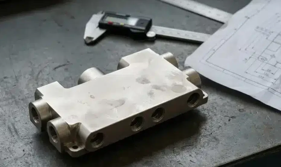
The brief describes a CNC-machined liquid-cooling manifold for an electronics cooling system. The proposed body is 6061-T6 aluminum, approximately 150 × 75 × 35 mm, with mounting features, a main coolant gallery and multiple branch connections.
The design brief specifies one inlet and eight outlets with M12 × 1.5 internal threads. This engineering case review focuses on the manufacturing and inspection decisions around those passages and sealing interfaces. It does not present a verified service-pressure, flow-balance or leak-rate result.
| Project input | Requirement in the brief |
|---|---|
| Material | 6061-T6 aluminum |
| Approximate body size | 150 × 75 × 35 mm |
| Connections | One inlet and eight outlets |
| Thread specification | M12 × 1.5; 6H internal thread called out |
| Port-position requirement | ±0.05 mm, to be interpreted with the drawing datums |
| Sealing-interface finish | Ra 0.8 µm, a design requirement rather than a reported measurement |
Start from the sealing mechanism
A thread designation specifies thread form and pitch. It does not independently define a complete liquid seal. The fitting interface must establish whether sealing occurs at an O-ring, a face, a gasket or another specified feature.
That choice governs the important geometry: sealing diameter, face or groove, fitting depth, mating component and assembly condition. Thread acceptance and sealing acceptance therefore need to be treated separately.
The Ra 0.8 µm requirement in this brief is not a universal rule for every manifold. A useful inspection instruction identifies the actual sealing surface and the measurement method, and includes any applicable form requirement.
Use a common datum strategy across the ports
The proposed route begins by squaring the billet and establishing the datums used to locate the coolant passages, ports and mounting holes. External features and mounting ears can then be machined in a sequence that preserves access to the later drilling and finishing operations.
Intersecting passages require a clear sectioned drawing. The number of drill operations, internal branches and external ports are different counts; they should not be used interchangeably. Any access opening that needs a plug becomes an additional sealing interface.
Features machined from different faces need to remain related to the specified datums. Workholding and the sequence of material removal should also account for distortion; aluminum’s thermal conductivity does not eliminate that risk.
Address the passage intersections
Cross-drilling can leave burrs at internal intersections and trap chips beyond the external line of sight. Deburring only the visible port mouths does not demonstrate that the coolant route is clean.
The finishing and cleaning method needs to address the actual passage geometry. The inspection plan should specify how intersection condition and cleanliness are checked before fittings or plugs obscure access.
These checks serve a different purpose from measuring the external body. A manifold can satisfy its outside dimensions and still need attention inside the coolant path.
Connect each requirement to an inspection method
| Feature or risk | Inspection focus |
|---|---|
| Port position and mounting alignment | Measure against the drawing’s datum references |
| Internal threads | Check the specified class and usable engagement |
| Sealing surface | Verify the specified roughness and any required form limits |
| Internal passages | Check intersection deburring and agreed cleanliness |
| Fittings and plugs | Confirm the intended sealing interfaces and assembly condition |
| Leak performance | Test against an agreed boundary, condition and acceptance criterion |
Leakage, pressure integrity and flow distribution are different verification tasks. Passing a dimensional check or a basic leak check does not establish all three.
Define the test conditions before claiming a result
A useful leak-test record identifies the test medium, pressure, temperature, hold time, acceptable leakage and test population. It should also identify the fittings, plugs and seals included within the test boundary.
A result applies to those documented conditions. It should not be extended to every coolant, service pressure or temperature without supporting evaluation. The available project brief does not establish a quantified leak-performance result, so none is claimed here.
For a similar component, provide a sectioned model, coolant and operating conditions, fitting specification, sealing details, cleanliness requirement and desired acceptance test. Review the CNC machining route and passage-drilling requirements with those inputs together.