Project overview
The project brief describes a single-cavity aluminum tool for a consumer-electronics enclosure measuring 85 × 55 × 18 mm, with a nominal 2 mm wall. The proposed tool material is 7075-T6 aluminum and the intended production target is 1,000 shots.
This engineering case review covers the machining and initial validation questions raised by that brief. The initial trial described in the source account is 30 T1 shots. That is an early tryout milestone, rather than demonstrated tool life across the complete production target.
| Project input | Brief specification |
|---|---|
| Application | Consumer-electronics enclosure |
| Nominal enclosure size | 85 × 55 × 18 mm |
| Nominal wall | 2 mm |
| Tool material considered | 7075-T6 aluminum |
| Tool arrangement | Single cavity |
| Production target | 1,000 shots; distinct from initial T1 evaluation |
Choose the tool material for the molding application
Aluminum tooling can be evaluated for a limited initial run when machining access, tool revisions and the expected production demand are important. The decision needs to include the resin, cavity geometry, pressure and temperature, finish requirement and likely wear locations.
7075-T6 identifies an aluminum alloy and temper. Higher material strength alone does not establish a mold’s wear life, and a target shot count does not automatically qualify the tool. Tool economics also depend on design complexity, the finishing work and the expected number of changes.
For this reason, the aluminum-versus-steel choice should compare the complete tooling plan instead of relying on a universal lead-time or price rule.
Settle resin, shrinkage and mold functions together
The molded resin grade is a necessary input to the released tool design. Shrinkage compensation needs a clear basis and should be related to the actual resin and molding conditions. A generic ABS or PC/ABS label is not enough to define a final cavity-compensation value or a fire-performance rating.
Draft, gate location, runner, venting, cooling and ejection have to work together. They determine whether a machined cavity can fill, cool and release the enclosure without unacceptable dimensional or cosmetic effects.
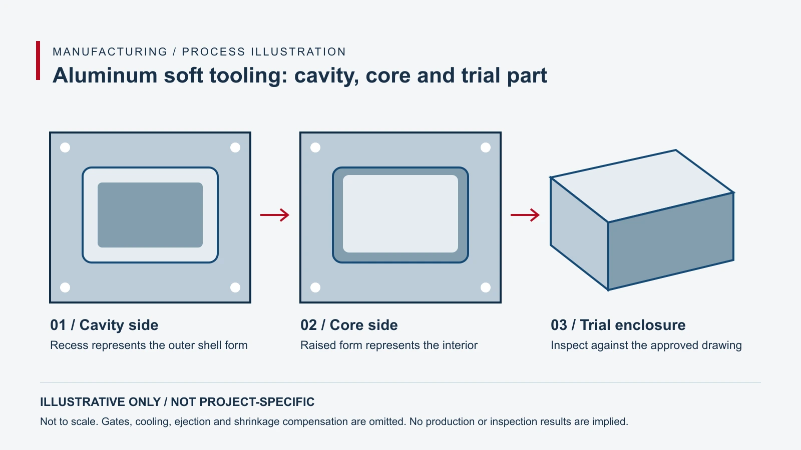
The diagram distinguishes the cavity side, core side and trial part. It does not specify a manufacturable tool or replace the approved design.
Machine deep features with the final inspection in mind
The proposed route combines milling, drilling, tapping, deburring and polishing. Roughing establishes the bulk form; finishing needs to deliver the specified cavity geometry while preserving access to deep pockets and narrow features.
Long tool reach can increase deflection. Where access permits, a shorter, more rigid cutter and a suitable finish strategy can reduce the risk of leaving excess material. Inspection should address the bottom of a deep feature as well as its accessible opening.
Surface appearance and surface roughness should be specified clearly. An SPI finish class and an Ra value describe different aspects of the surface and should not be treated as interchangeable labels. The chosen polish and its inspection method need to match the part’s functional and cosmetic requirements.
Define what T1 does and does not demonstrate
T1 evaluation is an opportunity to check initial filling, ejection, appearance and molded dimensions. It should identify the resin, molding conditions, sample sequence and measurement conditions so that a dimensional result can be interpreted.
| Evaluation | Question to answer |
|---|---|
| Filling | Does the enclosure fill as intended under the trial conditions? |
| Ejection | Can the part release without sticking, damage or unacceptable marks? |
| Dimensions | Do measured parts satisfy their specified tolerances after the agreed conditioning period? |
| Appearance | Do the designated cosmetic surfaces meet the agreed criteria? |
| Tool condition | What changes are needed before the next trial or production stage? |
A 30-shot trial does not establish dimensional consistency or tool condition after 1,000 shots. Those conclusions require a later production record. The present review therefore keeps the production target separate from initial trial scope.
Engineering takeaway
The key decision is not simply whether aluminum is machinable. It is whether the selected tool, resin, cavity design, finishing route and trial plan fit the enclosure’s requirements and expected production demand.
For a similar project, share the enclosure model, actual resin grade, quantity, cosmetic surfaces, dimensional requirements and validation stage. A CNC milling review can then consider tool access and finishing alongside the molding requirements.
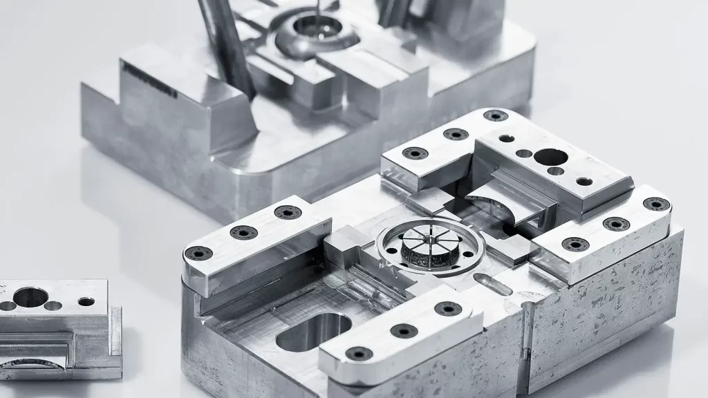
The main photograph is a Prolean factory-library tooling illustration. It is not identified as this enclosure’s tool, and its alloy cannot be established from the photograph.