

Trapezoidal thread forming
You need to make trapezoidal thread forms, but are unsure of where to begin? This is the guide for you. Trapezoidal Threads are the workhorses of mechanical systems. They deliver smooth power transmission to your machine tools and lifting equipment.
These 30-degree angled threads with flat crests and roots are superior to standard V-threads and are superior to the V-shaped ones on screws and bolts because they provide superior load capacities and low friction for linear motion. Understanding the basics is important when setting up thread milling operations or deciding whether to use thread machining as an alternative.
We offer comprehensive custom machining and professional thread tapping solutions at Prolean Tech. Our team has many years of experience in producing trapezoidal-shaped threads, including all standard sizes and materials.
What Is a Trapezoidal Thread Form
The geometry of trapezoidal threads is unique and sets them apart. These threads are ideal for power transmission and linear movement applications. Trapezoidal threads are essential to mechanical systems. Let’s examine their fundamental characteristics.
Thread Profile Characteristics
Trapezoidal threads have flattened crests and roots and sloped flanks. This geometry is different from the standard V-threads found in fasteners. Trapezoidal threads are easier to manufacture and have a higher load-carrying capacity than square threads. They are ideal for applications that require controlled linear motion while under heavy loads.
ISO standards specify that the thread angle for metric trapezoidals is 30 degrees. The trapezoidal shape of these threads is created by this angle. Each side slopes inward 15 degrees. This geometry is better for balancing strength, manufacturing, and operational efficiency than square threads.
Thread Designation System
The thread designation format is standardized. The symbol “Tr”, followed by the nominal diameter and pitch, indicates a trapezoidal thread in metric. Tr 60 x 9, for example, designates a thread with a nominal diameter of 60mm and a pitch of 9mm. This system of clear labeling helps manufacturers and engineers to communicate specifications across projects and industries.
Common Applications
Many industries and mechanical systems use them. Trapezoidal threads are used in lathe leadscrews to convert spindle movement into carriage movement. Vises use them to efficiently generate clamping forces. These threads are used in machine tool positioning systems. Jacks, valve stems, and adjustable mechanisms also rely on them. The versatility and reliability of these threads explain their wide adoption in mechanical engineering.
Trapezoidal Thread vs Metric Acme Thread
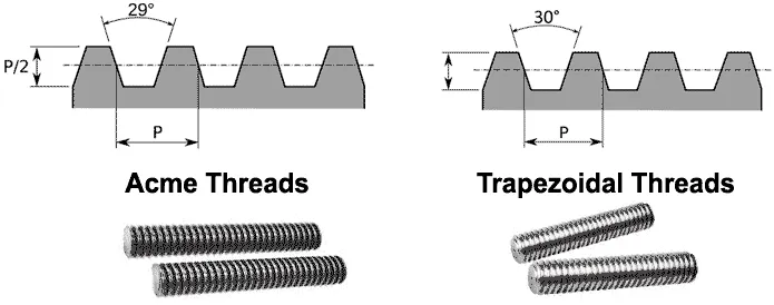
Trapezoidal Thread vs Metric Acme Thread
By understanding the differences in metric Acme terminology and trapezoidal sizing, you can avoid costly manufacturing mistakes. These thread types are distinct, despite being often misunderstood. Clarify the differences between these thread types and their practical application.
Differences in Thread Angle
In practice, metric trapezoidal threads and Acme threads are not interchangeable. Technically, the term “metric ACME” is incorrect. ACME threads have a 29-degree angle and are imperial-based. Trapezoidal threads in metric have a 30-degree angle.
Standard Specifications
ISO 2904 and DIN 103 are the standards that govern the metric threads. These standards define the dimensions, tolerances, and designation methods. European manufacturers use mostly metric trapezoidal hex threads. ISO allows for different pitches per diameter, while DIN 103 specifies a specific pitch-diameter combination. Both standards guarantee compatibility and proper functionality.
The Difference is Important
In practice, the one-degree difference in angle is significant. When ACME threads are mated with trapezoidal ones, the result is a poor fit and premature wear. The flanks are not aligned properly and create high stress points. The manufacturers must use the correct inserts and tools for each thread type. The thread strength and reliability are compromised by mixing standards, which can lead to mechanical failure.
CNC Threading Methods for Trapezoidal Threads
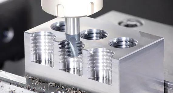
CNC thread cutting process
Single-point Threading
Trapezoidal threads can be produced with maximum flexibility using single-point threading. Cutting tools that are properly shaped remove material in multiple passes. The profile of the tool must match exactly that of the thread. CNC lathes can control the tool position and rotation of the workpiece with precision to create accurate thread geometry. This method can be used for both internal and external threads.
Selecting the right inserts is the first step. Carbide inserts are available in standard sizes for trapezoidal profiles. The angle of 30 degrees must be metrically equivalent. The tool height is adjusted to align the cutting edge with the centerline of the workpiece. A proper setup will ensure that the thread depth is correct and the flank angles are accurate throughout the entire machining process.
Thread Milling Advantages
Thread milling offers distinct advantages for trapezoidal-shaped thread production. The thread is created by a rotating cutter that follows a helical path. This method is ideal for machining materials with high hardness or threads of large diameter. Thread mills are able to produce different sizes using a single tool. This increases efficiency. In many applications, the process produces less vibration than one-point threading.
Milling is particularly beneficial for trapezoidal internal threads. This process is more efficient than tapping in terms of chip removal. Thread mills produce clean threads from materials that are difficult to machine, such as titanium and stainless steel.
Alternating Flank Infeed
When cutting trapezoidal threads, the tool’s life can be extended by using alternate flank infeed. During successive passes, the technique alternately engages the left and right flanks. This technique distributes tool wear evenly along the cutting edges. This method is especially useful for trapezoidal threads with large pitches. This method is more complicated to program but produces a better surface finish.
The tool deflection is reduced with alternate infeeding compared to radial plunging. Cutting forces are reduced because each cut removes less material on one side. This improves the dimensional accuracy of long threads.
How to Cut Threads On A Lathe
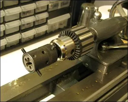
Thread cutting on a lathe
Manual Lathe Setup
The threading process on a manual machine requires careful coordination and setup. The quick-change geared connection connects the spindle movement to the leadscrew. Gear combinations determine thread pitches. Gear selection is guided by charts on the headstock of the lathe. Trapezoidal threads in metric require specific ratios of spindle to leadscrew rotation.
The toolpost must be positioned at the correct height. A center gauge is used to align the tool perpendicularly to the work axis. The tool tip must be positioned exactly on the centerline of the workpiece. Incorrect height errors can lead to incorrect thread depths and poor flank engagement. Spending time on the setup will prevent threading issues and material waste.
Threading Tool Selector
The correct tool geometry is essential for thread cutting. HSS tools are available in a profiled form for trapezoidal threads. Carbide inserts provide better performance and consistency. Inserts must be angled at the correct 30-degree angle to accommodate metric threads. The tool manufacturers offer inserts in different sizes that are specifically designed for a trapezoidal profile.
To reduce vibration, the tool overhang should also be minimised. A rigid tool mount prevents chattering during cutting. Sharp cutting edges produce a better surface finish. Dull tools produce excessive heat and a poor thread quality. Regularly inspecting and replacing tools ensures consistent results across production runs.
Steps to Cut Trapezoidal Threads on a Lathe:
- Steps to Cut Trapezoidal Threads on a Lathe
- Set up the correct gear train for the required pitch.
- Touch off and make a scratch pass to verify pitch with a thread gauge.
- Increase depth using the compound rest in small increments (e.g., 0.002–0.005″).
- Retract the cross slide at the end of each pass to protect the tool.
- Re-engage the half-nut at the same threading dial mark every pass.
- Switch to a finishing pass around 0.001″ depth with cutting fluid applied.
Metric Trapezoidal Thread Standards (ISO 2904 & DIN 103)
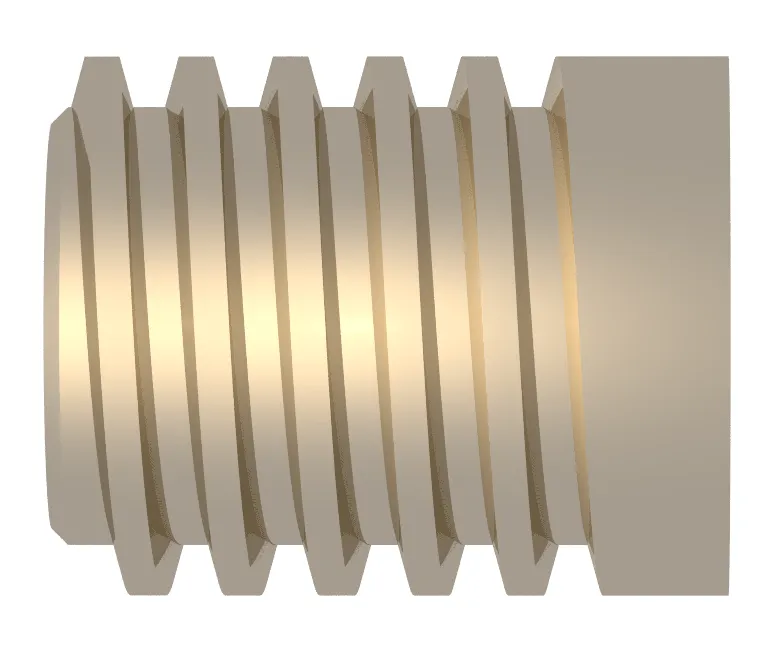
Trapezoidal Thread Form
Engineers typically specify metric trapezoidal threads according to DIN 103 or ISO 2904, which define the standard dimensions, tolerances, and designations for Tr threads.
ISO 2904 Standard
ISO 2904-1977 specifies the general-purpose metric thread system. This standard applies to threads used in mechanisms and structures. The standard specifies the thread profiles, tolerances, and designation methods. The standard allows for different pitch options per nominal diameter. This flexibility is a great way to meet the diverse needs of industries.
The range of tolerance classes is from coarse precision to fine precision. The selection is based on the application and manufacturing capabilities. Costs are higher, but performance is better with tighter tolerances.
DIN 103 Requirements
DIN 103 contains detailed specifications for trapezoidal metric splines. This German standard is older than the ISO standard, but it continues to be widely referred to. DIN 103 specifies pitches for specific diameters. The standard specifies different clearances for minor and major diameters. Minor diameter clearance is typically two to three times greater than major diameter clearance.
The thread sizes can range from 8mm to 300mm. The preferred pitch values are based on each diameter range.
Tolerance classes
To indicate the precision of a trapezoidal thread, letter-number combinations are used. The pitch diameter tolerance has an impact on thread fit and backlash. A tighter tolerance on pitch diameter reduces play in the mechanism. For major and minor tolerances, “H” is used for internal threads (and “h” for external threads) to indicate zero fundamental deviation.
Tolerance calculations for multiple-start threads are modified. Tolerance values for pitch diameter are multiplied by factors based on the start number. For threads with two starts, the factor is 1.12, for threads with three starts, it’s 1.25, and for threads with four begins, 1.4. These adjustments are made to account for the longer thread lead and to ensure that the thread functions properly.
Try Prolean Now!
Thread Machining Best Practices
Material Considerations
The machining parameters for different materials will differ. Aluminum can be cut easily at high speeds with light feeds. Steel requires moderate speeds and adequate cooling. Stainless steel requires lower speeds with high-pressure coolant. Material hardness directly affects tool life and finish quality.
Work-hardening materials like stainless steel present special challenges. Multiple light passes prevent excessive work hardening between cuts. Sharp tools and the right speeds reduce strain hardening. For very hard materials, thread grinding may be required. Understanding the material properties will help you select the best cutting strategy.
Optimizing Feed Speed
Cutting speed impacts both productivity and threading quality. In general, lower speeds produce a better finish when threading. The majority of manual threading operations are performed at 30-100 RPM, depending on the diameter. With the right programming, CNC machines can run faster. The optimal speed is a balance between finish quality and production time.
In CNC threading, the feed rate equals the thread pitch. Automatically, the machine coordinates spindle and tool speed. The leadscrew and gearing are responsible for the proper feed in manual threading. By maintaining a constant feed, thread errors can be prevented. When threading, speed changes can cause visible marks as well as dimensional issues.
Quality Control Methods
Thread gauges are used to verify the accuracy of dimensions after machining. The GO/NO-GO gauges are used to quickly determine if the threads are within tolerance. The threads of GO gauges must be smooth over the entire length. NO-GO gauges must not be engaged beyond the first rotation. This simple test will confirm the proper thread diameter and pitch diameter.
Try Prolean Now!
Troubleshooting common threading issues
The following are some common problems that can be faced during thread forming.
Chatter Problems
Chatter can lead to a poor thread finish and an inaccurate thread size. Vibration problems are largely caused by tool overhang. Reduced tool stick-out increases rigidity and reduces chatter. Vibration is also affected by the support of the workpiece. When threading long, thin parts, you need a steady rest or center support. Often, reducing speed can eliminate chatter. A slight increase or decrease in speed can move frequencies away from resonance.
Thread Form Errors
Incorrect angles can be caused by incorrect inserts or improper tool grinding. Angle problems can be identified by using thread gauges. For trapezoidal threads, the 30-degree angle should be exact. The tool angle error prevents proper mating of standard nuts or mating components.
Thread depth errors cause fit problems. Threads that are too shallow will be weak and easily stripped. Too deep can cause a tight fit or even prevent assembly.
Tool Wear Management
The thread diameter changes over time as the tool wears. Inspections are done regularly to detect wear before the parts become out of tolerance. Wear patterns are visible on the tool tip and flanks. In production environments, carbide inserts retain accuracy longer than HSS.
The life of a tool is affected by the cutting conditions as well as the material used for a workpiece. Tool life is shorter for hard materials than for soft ones. The right speeds and feeds will maximize the tool’s life. Coolant application extends the cutting edge’s durability and reduces heat. By rotating indexable inserts, you can maintain consistent quality.
Conclusion
Trapezoidal threads are a crucial element of modern mechanical and manufacturing design. This knowledge allows manufacturers to create quality components by understanding standards and mastering machining methods. Proper technique for trapezoidal thread form is essential for success in countless applications, whether you are cutting threads with a manual lathe on a CNC machine or programming the operation.
Prolean Tech is ready to assist you with all your thread machining needs. We can machine metric trapezoidal threads to ISO standards in steel, stainless, and non-ferrous alloys, from prototypes to production. Call us to discuss threading needs and learn how our expertise can help you with your most difficult machining requirements.


0 Comments