Project overview
A repeat-order brief for 1,200 brass HVAC orifice plates raised a manufacturing question: could fibre laser cutting replace an earlier waterjet route while retaining the approved part geometry?
This engineering case review examines that process decision using the specified plate dimensions and critical features. Its focus is the qualification of an alternative cutting route, rather than a claim of measured cost savings or airflow performance.
| Project requirement | Specification in the brief |
|---|---|
| Application | HVAC airflow assembly |
| Material and thickness | Brass sheet, 1.5 mm |
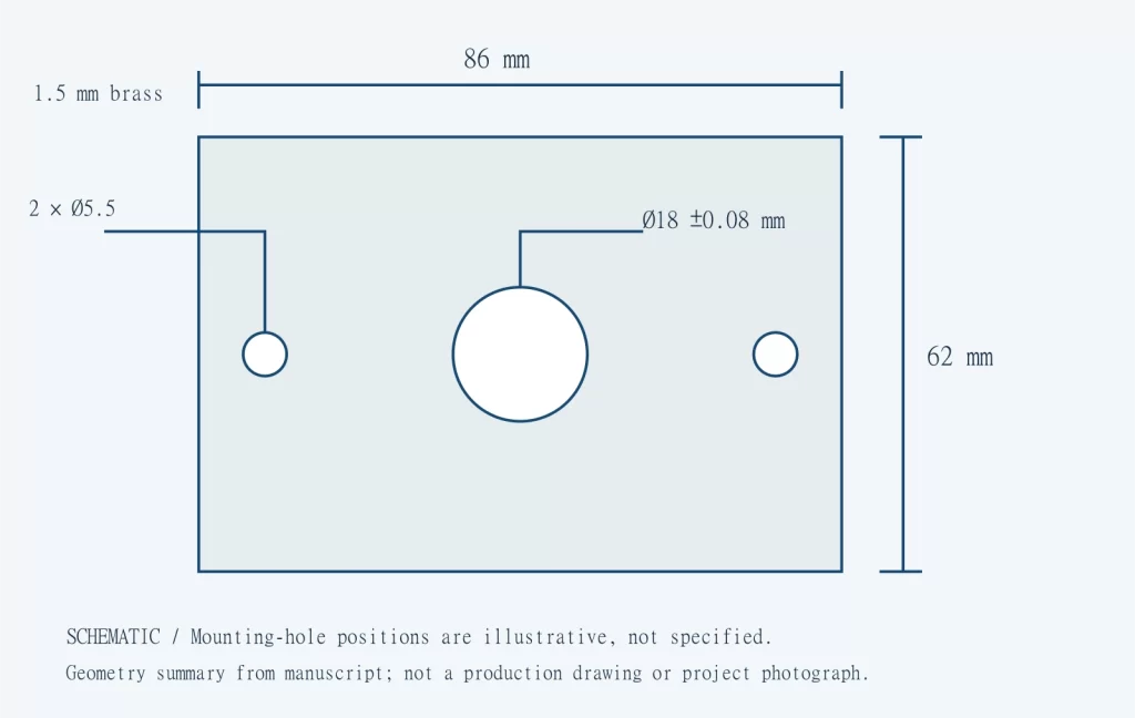
| Outside profile | 86 × 62 mm |
| Central opening | Ø18.00 ±0.08 mm |
| Mounting holes | 2 × Ø5.50 ±0.10 mm |
| Order quantity in the brief | 1,200 pieces |
Why evaluate a different cutting route?
The geometry had already been used with a waterjet process. For a larger repeat order, cutting time, abrasive removal, drying, handling and final inspection all contribute to the manufacturing route. Laser cutting was therefore a candidate for evaluation on the thin brass sheet.
The comparison should cover the full route, not cutting speed alone. A faster cut can lose its advantage if it requires additional deburring or produces more rejected parts. Without comparable production records, the engineering decision can be explained without assigning a cost-saving percentage.
Waterjet and laser cutting also produce different edge characteristics. A change of process needs to demonstrate that the finished features still satisfy the drawing and assembly requirements.
Control the opening without changing the design
The Ø18.00 mm opening has drawing limits of 17.92–18.08 mm. The cutting program should preserve that nominal design while using the appropriate kerf compensation for the actual process.
A compensation adjustment changes the cutter path relative to the design contour. It should not be confused with changing the customer’s approved hole geometry. Trial parts provide a way to evaluate the resulting opening size, taper and burr before releasing the production route.
The measurement plan should specify the inspection face and the method used to evaluate the opening. For a cut edge, a single diameter reading may not describe taper or local irregularity through the sheet thickness.
Plan the cutting and handling sequence
Cutting the internal features before the outside contour keeps the plate supported by the surrounding sheet during the critical cuts. A practical sequence is to cut the two mounting holes, cut the central opening and then release the outside profile.
Trial evaluation should include parts from different positions on a sheet. Selecting only neighbouring parts can overlook position-dependent changes. Once a route is qualified, sampling during the run should be connected to a defined action when size or edge quality begins to drift.
If maintenance and a cutting-offset adjustment are made together, their separate effects should not be assumed. Verification pieces should establish the condition of the process before the next sheet is released.
Match inspection to the functional features
| Feature | What to check | Why it matters |
|---|---|---|
| Flow opening | Diameter, taper and local cut quality | Preserves the specified passage geometry |
| Mounting holes | Size and position relative to the drawing datums | Maintains the mounting arrangement |
| Plate profile | Length, width and contour | Supports assembly fit |
| Flatness | Defined numeric requirement and measuring method | Checks seating rather than appearance alone |
| Edges and faces | Burr, sharp edges, scratches and residue | Controls handling and assembly condition |
A visual check for rocking on a flat surface is useful, but it is not a substitute for a numeric flatness measurement. Likewise, preserving the orifice diameter does not by itself establish equivalent airflow across all operating conditions.
Engineering takeaway
The useful result of this review is a qualification plan: retain the approved geometry, evaluate the critical opening on trial parts, control the cutting sequence and define the inspection checks before scaling the route.
The dimensions and quantity above describe this project brief. They are not a general tolerance, lead-time or production-capability promise. Process suitability and acceptance criteria remain drawing- and order-dependent.
Planning a similar part? Share the brass grade and thickness, drawing, quantity, critical openings, permitted edge condition and flatness requirement for a laser-cutting review or a comparison with waterjet cutting.