
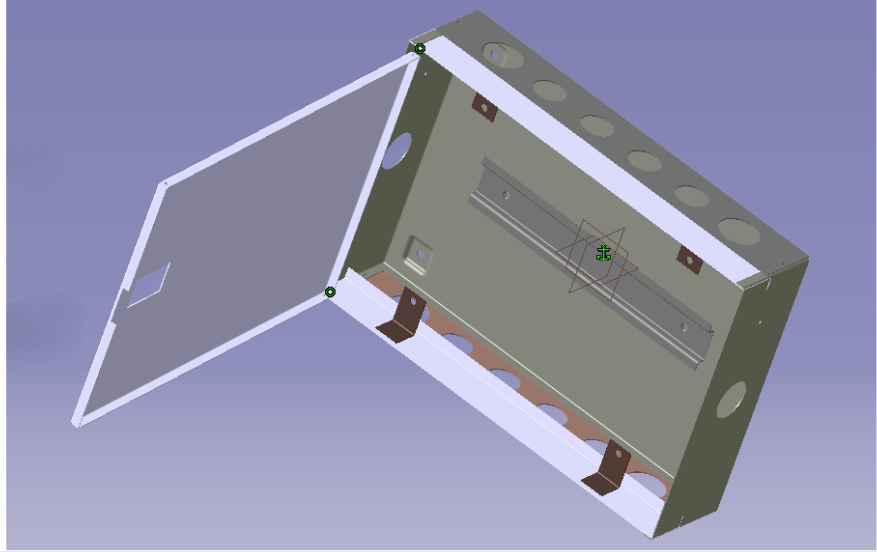
The challenge: a sound drawing, three hard constraints
When the client’s engineering team sent over the 3D model of their miniature-circuit-breaker enclosure, the design itself was right. What needed solving was how to build it — and at 1.5 mm, three decisions shaped everything that followed.
Welding was off the table
At 1.5 mm, welding the individual panels would put heat-affected zones into thin material and distort a box that has to close square. So the whole architecture was rebuilt around a single cross-shaped blank: the back panel, both side walls and the top and bottom flanges are one piece of steel, folded on four bend lines. There are no corner welds to distort, because there are no corner welds.
Four bends on one precision budget
The main shell still carries four 90° bends at different positions. Each one was calculated for the right tonnage and formed on a CNC press brake — then verified with a digital bend gauge, because the overall enclosure dimensions only work if every bend holds ±1°.
Punch first, bend after
Most blanks needed both punching and bending. Post-form punching is slower and less accurate, so the batch was routed punch-flat first, then bend — a sequencing choice that keeps hole position within ±0.3 mm and takes a whole operation out of the route.
Punch everything first, then bend. It keeps every hole within ±0.3 mm — and takes a whole operation out of the route.
Design review: twelve DFM checks, four that changed the build
The model went through a full design-for-manufacturing review before anything was cut. Twelve points were checked; four findings actually changed the design:
- Corner reliefs, 2–3 mm — notches at all four open corners remove the tearing risk as the flanges fold to 90°.
- Bend-to-hole clearance, 4–5 mm — every hole sits at least 2–3 × thickness + bend radius away from a bend line, so forming never pulls a hole out of position.
- A third DIN-rail bracket — the 400 mm rail span would sag under MCB load on two supports; one added at ~135 mm pitch closes the gap.
- A clear cable channel — gland entry to DIN terminals stays unobstructed within the 100 mm depth, leaving room to wire the enclosure in the field.
The other eight checks — tool reach, interference, service access and the rest — passed as designed. The full review is below.
| # | Review item | Finding / recommendation |
|---|---|---|
| 1 | Bends | Bend count and sequence good; 2–3 mm corner relief notch recommended at all four open corners |
| 2 | Bend radii | Keep bend radius equal to thickness (1.5 mm) |
| 3 | Bend feasibility / tool access | Punch and die reach the bending position without collision |
| 4 | Hole placement | Gland knockouts sit 40 mm from sheet ends |
| 5 | Bend-to-hole clearance | ~4–5 mm (≥ 2–3 × thickness + bend radius) |
| 6 | Tool accessibility | Standard punch and brake tooling reaches every feature in the planned process order |
| 7 | Cable-routing space | Clear channel from gland entry to DIN-rail terminals within the 100 mm depth |
| 8 | Assembly sequence | Body → DIN rail → top/bottom plates → hinge and door |
| 9 | Internal mounting (DIN rail) | Support spacing checked against sag over the span |
| 10 | Door & hinge clearance | 1.5–2 mm running clearance recommended |
| 11 | Potential interference | None found |
| 12 | Service access | Terminals, gland and rail screws reachable with the door fully open |
Full DFM review as it was delivered to the shop floor.
From blank to assembly
Five blanks left the laser and met again at the assembly fixture: the body shell, the front door, two identical gland plates and the DIN rail. Here is how each step ran.
Precision laser cutting
A 3 kW CNC fiber laser cut every blank — including the 600 × 500 mm body blank, which arrives as one cross-shaped piece carrying the back panel, both side walls and the top and bottom flanges. Laser cutting holds ±0.1 mm, which is what makes the ±0.5 mm overall assembly tolerance possible.
Punching the knockouts
All holes were punched on flat blanks with matched die-punch sets, holding ±0.13 mm: four Ø22 mm gland knockouts and four corner reliefs in the body; the viewfinder cutout and hinge-pin holes in the door; seven Ø25 mm knockouts in each gland plate; and a single Ø5 mm mounting hole in the rail.
CNC press-brake bending
Every part except the two gland plates was formed on a CNC press brake (3 tonnes max). Bend radius equals the 1.5 mm sheet thickness, K-factor 0.44 — a bend allowance of ~2.7 mm per 90°. The flat patterns below show how the blanks were laid out before forming.
For engineers: bend schedule
All 8 bends — R1.5 mm, K 0.44, allowance 2.7 mm per 90°
| Part | Bend | Bend line | Direction | Bend length |
|---|---|---|---|---|
| Main body shell | 1 | x = 100 mm, full height | Up | 300 mm |
| 2 | x = 500 mm, full height | Up | 300 mm | |
| 3 | y = 100 mm, full width | Up | 400 mm | |
| 4 | y = 400 mm, full width | Up | 400 mm | |
| Access door panel | 1 | x = 390 mm, full height | Return (inward) | 300 mm |
| 2 | y = 10 mm, full width | Return (inward) | 400 mm | |
| 3 | y = 290 mm, full width | Return (inward) | 400 mm | |
| DIN rail bracket | 1 | y = 30 mm, full width | Up | 40 mm |
All bends angle-verified to 90° ±1° with a digital gauge.
Coating each part on its own
The coat went on before assembly, part by part: alkaline degrease and rinse, electrostatic spray of an epoxy-polyester hybrid powder at 60–100 kV, then 15 minutes at 190 °C for a finish up to 80 µm. Coating an assembled enclosure gives poor coverage in overlaps — and powder overspray can paint-lock a hinge or a gland-plate fastener shut.
Assembly sequence: five steps, all mechanical
- Position the body shell on the assembly fixture, open front facing the operator.
- Rivet three L-brackets to the back wall.
- Mount the TS35 DIN rail onto the bracket flanges.
- Fasten the top and bottom gland plates with rivets and screws.
- Fit the hinge leaf and hang the three-side-flange door on its pins.
Five coated parts, zero welds — and a door that swings true on its pins the first time.
Validation, documentation, delivery
Validation ran in four passes. Incoming parts: blank dimensions verified on a digital caliper and CMM to better than ±0.2 mm. Fit-check: bracket-to-body gap measured under 0.3 mm with filler gauges; alignments by trial fit; DIN-rail seating by snap-fit test. Function: door swing, cable routing and latch engagement tested by hand, with dummy MCB modules on the rail to confirm internal clearance. IP20: rigid test wire, finger probe, and finger probe with the door open.
Every stage was documented and shipped with the parts:
- Inspection reports, pass/fail at every stage
- Measurement reports — CMM, digital gauge, angle gauge, filler gauge, caliper
- IP20 test report — all three probe tests passed
- First-article approval, signed off before the run continued
The enclosure was packaged and delivered to the client’s facility within two days of final testing. It was the functional prototype they took to market — and the same enclosure is now being scaled for production with the design changes their engineering team confirmed after testing.