
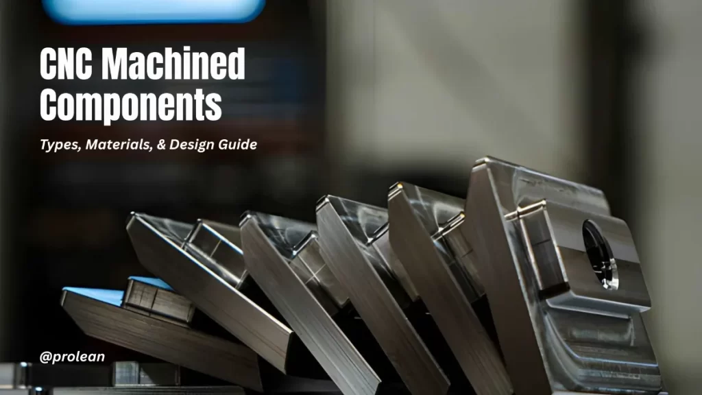
CNC-machined steel components
CNC-machined components are parts produced by removing material from a solid workpiece with computer-controlled machine tools. The machine follows programmed toolpaths to cut the stock into the required shape and size.
A typical component may start as an aluminum block, steel bar, brass stock, or engineering plastic. A milling cutter can then remove material to form pockets, slots, steps, and flat surfaces. Drills create holes, while tapping tools produce internal threads.
The component geometry determines the type of machining method used. Many prismatic parts can be manufactured on a 3-axis mill, and a 4-axis machine can turn the workpiece to access other faces. The 5-axis machine tool can minimize the number of workholding changes for complex, angled surfaces.
In addition to production parts, CNC-manufactured parts can also be custom assemblies that include complex features. A single face of a valve body may be subject to on demand manufacturing, like milling, drilling, boring, and tapping, while a shaft may only be turned and threaded.
A typical component may start as an aluminum block, steel bar, brass stock, or engineering plastic. Depending on the part geometry, the part may require milling, turning, drilling, boring, tapping, or other machining operations.
What Are CNC-Machined Components?
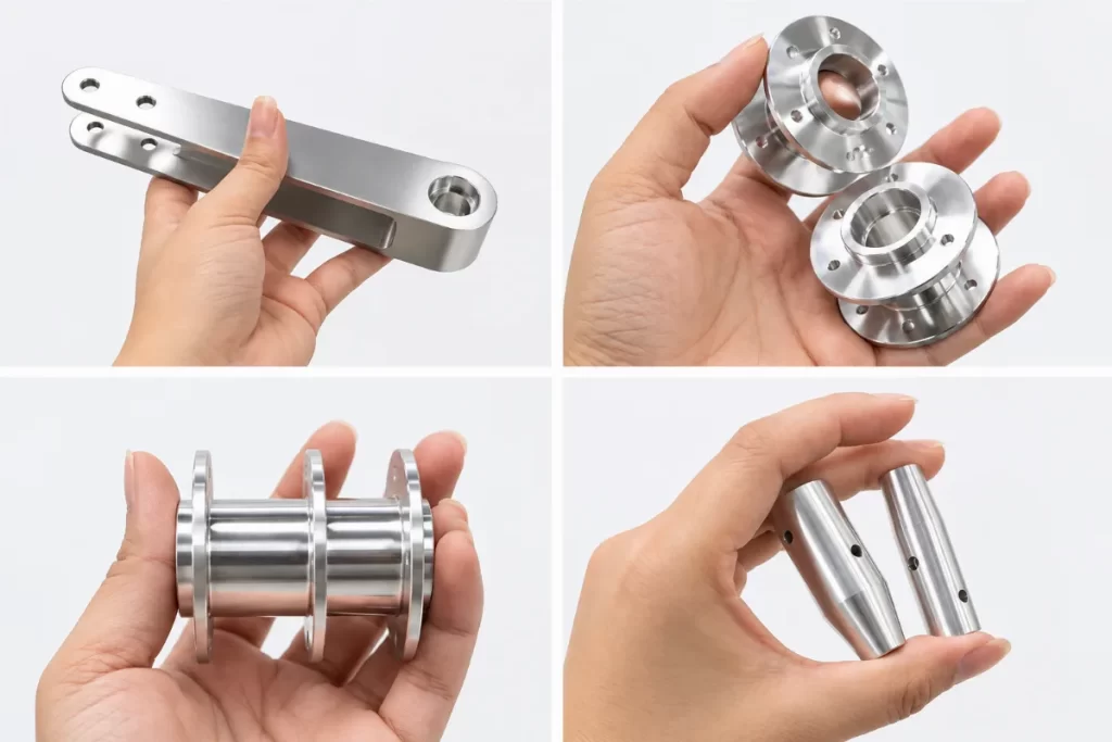
CNC-machined components
CNC-machined components are the parts produced through the process of removing material from a solid material with the help of computer-controlled machine tools. The CNC machine is programmed with the desired shape and size, and then moves the material through it to perform the cutting operation.
The material used can be a metal bar, plate, block, or plastic stock. CNC Operations remove material like turning, milling, drilling, boring, and threading.
A steel shaft may be a round bar, for instance. The machine can be rotated to the ends and turned to various diameters, cut a groove, drill a hole, and machine a thread. Facing, pocket milling, drilling, and tapping may be required for an aluminum housing.
Try Prolean Now!
How Are CNC-Machined Components Made?
Part Design
The process starts with a CAD model and an engineering drawing. The designer specifies the component’s geometry, dimensions, material, surface finish, etc.
The design should also account for how the part will be held and machined. The depth of pockets, narrow slots, inside features, and hard-to-reach surfaces can impact tool selection and setup.
A long cutting tool, for instance, might be needed for a deep pocket. The designer may provide suitable access or reduce the feature depth if reaching the full depth is not necessary.
Toolpath Planning
Once the design is finished, a CNC programmer will then write the machining sequence in a CAM software. The programmer selects suitable tools and determines the cutting for each feature.
Typically, the toolpath begins with operations that remove significant amounts of stock. The finishing operations finish the basic shape.
If the housing is to be machined, the programmer might have to start with the stock and then rough the external profile and pockets. The following operations, as per the drawing, can be performed after drilling, tapping, and finishing.
Machine Setup
The operator sets up the CNC according to the planned process. The cutting tools are inserted into the machine, and the work is held in a vise or chuck, mounted in a fixture, or in another appropriate workholding device.
Work coordinates and tool offsets are then determined. These positions indicate the machine’s location of the tools and the workpiece.
The operator also monitors tool movement during the first few strokes before the first cutting stroke. This helps detect incorrect offsets, tool positions, and setup issues before they affect the component.
Machining and Inspection
The CNC machine then executes the desired procedures. The operator observes the cutting process and verifies the component during production.
Inspection may be done after key operations, rather than at the end of the component. For instance, after boring, a critical bore can be measured, and the next operation can be performed.
Engineered parts are inspected for conformance to the engineering drawing, using appropriate measuring tools. The parts inspected can range from calipers, micrometers, bore gauges, and height gauges to coordinate measuring machines.
Best Design Practices for CNC-Machined Components
A CNC-machined component is easier to produce when the drawing matches what the machine and tooling can do efficiently. Small design choices can add another setup, require a smaller cutter, or create extra inspection work.
Put Tight Tolerances Only on Working Features
Begin with the dimensions that affect the component’s function. These can be bores, holes to be located, shaft fits, and mating surfaces. The other dimensions can typically be drawn with the general tolerance found on the drawing.
For instance, if a piece of hardware is not used in an outer dimension, a close tolerance is not beneficial to the component. It can still provide inspection work, and might need extra finishing.
Check the Component Size Against the Machine
A large component requires adequate space for the fixture, cutter, spindle, and tool movement. Another height issue may arise when a deep feature is accessed with a long tool.
Make sure the design is not too large or that the deepest feature being machined is not. A shorter, easier-to-maintain cutter may be possible with a small change in pocket depth.
Choose a Material That Fits the Job
Never choose material for its strength alone. Consider what is actually subjecting the component to. Take into account hardness, rigidity, chemical exposure, operating temperature, thermal movement, and surface conditions.
If unnecessary resistance is added to the material, it will increase machining time and tool wear. If the dimensions of the component are close, then it could also cause issues if the material is not thermally stable.
Give the Cutter Enough Access
The cutter must be in direct contact with the feature. Short- or long-reach tools may be required in deep, narrow pockets, areas with very small internal radii, and enclosed spaces.
Use wider openings and larger corner radii of interior corners where feasible. A larger cutter is typically easier to operate than a small cutter that is forced into a hole.
Reduce Extra Setups
Inspect the part the machinist worked on. Less repositioning and less alignment work when machine setup can produce multiple related features.
Avoid placing critical features on different sides. Provide a clear surface or locating feature for the second setup if the component must be flipped over.
Leave Enough Stock for Machining
There must be enough material in the raw blank to give the finished surfaces a clean-up. The allowance will vary depending on the condition of the stock, the size of the components, the material being used, and the type of machining process.
One shouldn’t use a generic allowance for all parts made on the CNC machine. If too little stock is used, the surface will be unfinished; if too much stock is used, more material will need to be removed.
For CNC-machined components, easy and cost-effective changes typically include functional tolerances, available features, appropriate material selection, fewer setups, and reasonable stock sizes.
Try Prolean Now!
Practical Design Rules for CNC-Machined Components
These rules address features that directly affect how a milling cutter enters, moves through, and exits the part.
Internal Corner Radius
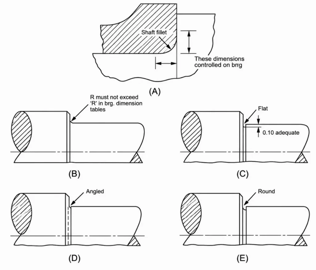
Internal Corner Radius Part
You can’t get a square internal corner using a normal milling cutter. It always has a round radius at the cutting edge.
Use the maximum radius that will fit the mating feature. If a smaller corner is needed, the machining operation may need a smaller cutter and additional tool path operations.
Thin and Tall Walls
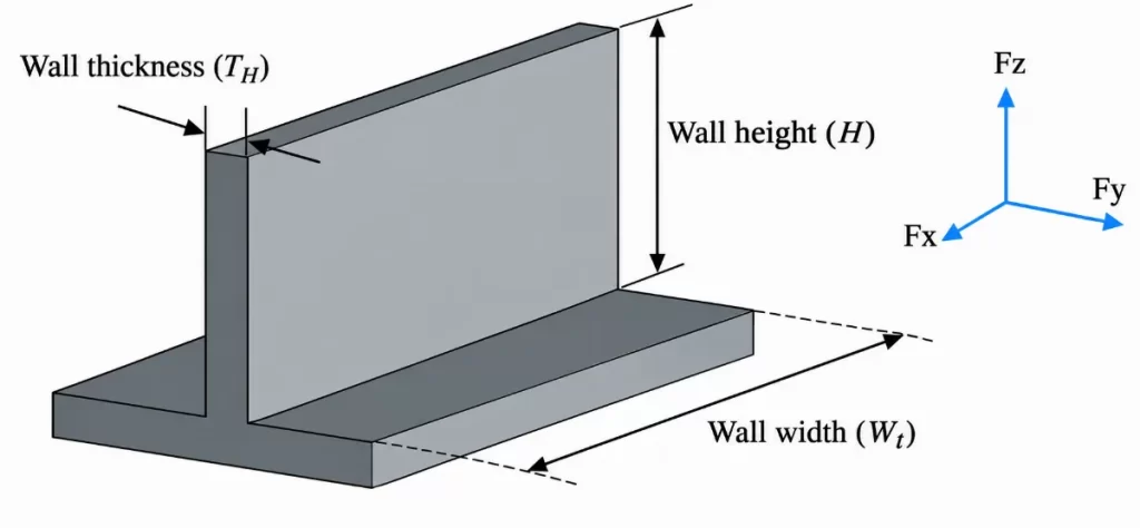
Geometrical structure of a thick-walled component
A tall, slender wall can be moved under the cutting pressure. This will lead to wall deflection, chatter, or post-cut dimension change.
Increase wall thickness and/or decrease the height of unsupported walls where possible. Another option is to use a supporting rib to help add stiffness without adding thickness to the entire component.
Deep Cavities
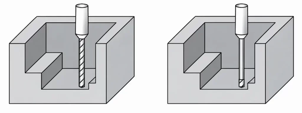
Deep cavity milling
Longer cutting tools are required in deep pockets. The longer a tool is, the more difficult it is to control deflection.
For most CNC parts, keep cavity depth within about four times the cavity width. Deeper cavities need longer tools, which can bend and vibrate more during cutting. Chips are also harder to clear from deep pockets. Making the cavity wider can give the cutter better access and provide more room for chip removal.
Machined Text
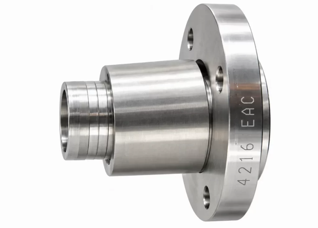
Text Engraved on Part
Adds cutting operations that don’t contribute to the primary shape of the part. Simplify lettering if necessary for identification.
Raised or embossed lettering takes more machining because the cutter must remove material around the letters. Engraved text is usually easier and faster because the tool only cuts the letters into the surface.
When designing a part for CNC machining, restrictions need to be considered. Certain shapes are not possible to make efficiently using standard CNC tooling. These limits should be evaluated before the component is produced.
Cutter Geometry
The surface produced depends on the cutter’s shape. A flat end mill is suitable for flat-bottom pockets, while a ball-nose cutter is used for curved pockets.
The corners on the inside of the object are also round, using the same radius. Having features designed for standard cutter sizes provides the machinist with a greater choice of cutter designs.
Cutter Access
A tool must have clear access to the surface. Enclosed areas, deep side features, or undercuts may block that path.
If the feature is not accessible via any existing direction, it might require a different tool, assembly technique, or manufacturing process.
Tool Deflection
The smaller the diameter and the longer the length, the easier it will bend when cutting. This can affect the end product and increase the risk of tool failure. If it is possible, use a larger cutter with the shortest possible reach.
Part Deflection
The component may also be vibrated while cutting. This is typical of thin walls, narrow ribs, and areas where little of the wall remains behind the cutting area.
Provide adequate support in these sections for the cutting forces. Workholding should allow access to features to be machined without blocking.
What Are the Common Types of CNC-Machined Components?
CNC-machined components are usually grouped by the type of work needed to produce them. The part may be mainly milled, turned, drilled, or produced with EDM. Some components need more than one process before they are complete.
CNC Milling Components
Parts with flat faces, pockets, slots, holes, steps, and non-circular profiles are generally milled components. The workpiece remains stable as the cutting tool traverses various areas of the part.
Typically, mounting plates, brackets, housings, fixtures, covers, and machine bases.
For instance, a mounting plate having a pocket, a plurality of tapped holes, and a bolt-hole pattern is typically accomplished by milling and drilling the holes. If features are to be placed on other faces as well, the machining plan may specify additional part positions.
CNC Turning Components
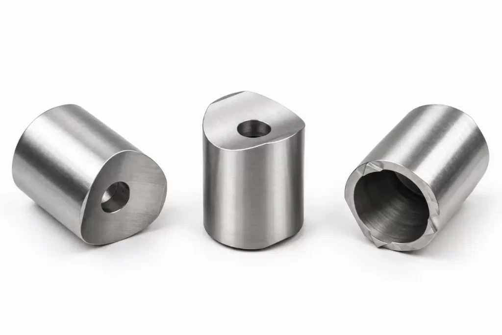
CNC Turned Components
Turned parts are primarily round and made as the material rotates against the tool. Typical parts include shafts, pins, bushings, sleeves, spacers, collars, precision trophy manufacturing, and threaded fittings.
Turning is an ideal process for parts that have multiple features along a single center axis. For instance, a shaft can have varying outside diameters, be grooved or threaded, and have a center bore. Such features may be created in the same turning operation.
Drilled and Bored Parts
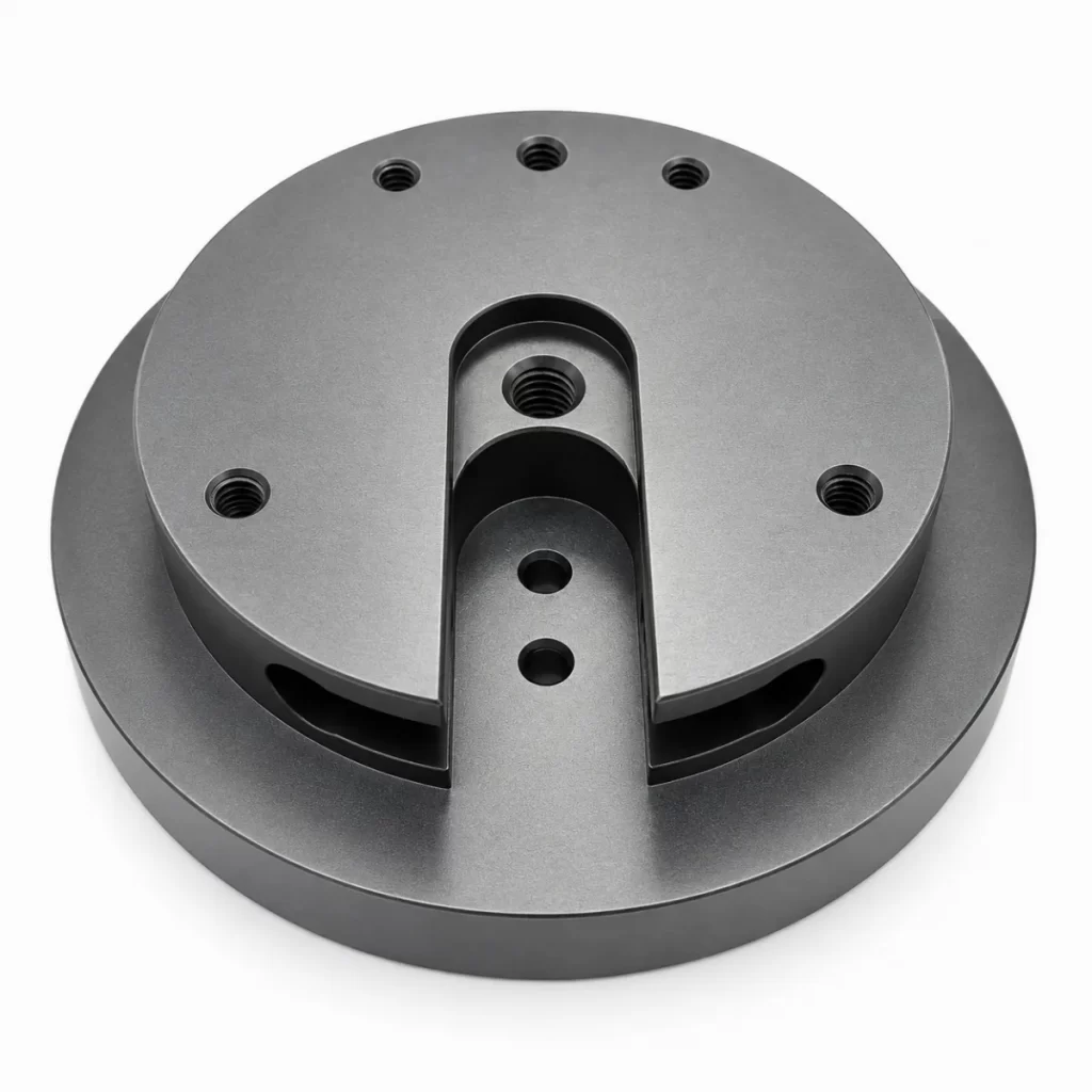
CNC Drilled Part
The difference between drilling and boring a hole is that boring is used to machine an existing hole to a more controlled diameter and geometry, while drilling is used to create a hole.
When the hole is an integral part of the mating feature, the difference is important. Sometimes a clearance hole will only require drilling; other times, it may be necessary to extend the precision bore or add a bearing seat.
Common applications include machine housings, engine parts, valve bodies, hydraulic parts, and bearing housings.
EDM Machined Components
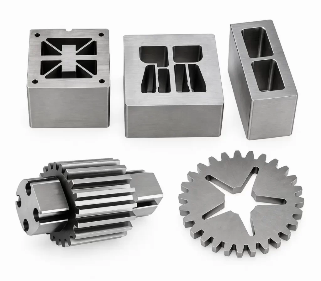
EDM Machined Components
When the feature is difficult to form with a conventional cutting tool, EDM is employed. The process uses electrical discharges to remove conductive material.
It is appropriate for small internal features, narrow slots, detailed cavities, and hardened tool components. For example, narrow internal features can be difficult to machine if a suitable milling cutter cannot reach them. In such cases, the feature may require a design change to improve tool access. EDM can achieve that without pushing a small cutting tool into an inappropriate machining situation.
Laser Cut Components
Laser cutting is primarily employed for flat sheet and plate components that need only to be cut into a profile, hole, or slot.
Common components are panels, brackets, covers, plates, and enclosures.
The laser-cut blank can also be processed into other CNC products. A plate, for instance, can be laser-cut to its external shape and then machined to create pockets, tapped holes, or precisely finished faces.
Custom Precision Components
Custom components are fabricated from a drawing, not a catalog component design. The shape and required properties dictate the required machining processes.
One component can be involved in turning, milling, drilling, tapping, boring, EDM, and finishing operations. For instance, a round housing can be rotated for the main diameter and bore before it is milled to provide mounting flats and drilled for the hole pattern.
The key aspect of this kind of work is to match each feature to an appropriate process. It is not always feasible to use separate processes for each feature, particularly where the component exhibits round, flat, internal, and detailed features.
What Materials Are Commonly Used for CNC-Machined Components?
The right material depends on what the component needs to handle. Strength, weight, corrosion resistance, wear resistance, temperature, electrical properties, and machining requirements all affect the choice.
|
Material |
Practical recommendation |
|
Aluminum |
• Use for lightweight housings, brackets, plates, structural parts, and agricultural machined components. |
|
Stainless Steel |
• Use for components exposed to moisture, cleaning agents, or corrosive conditions |
|
Steel |
• Use for shafts, gears, tooling, and load-bearing machine parts |
|
Titanium |
• Use for components where reducing weight without losing strength is a priority |
|
Engineering Plastics |
• POM: sliding parts, bushings, gears |
|
Composites |
• Use when low weight and high stiffness are required |
Try Prolean Now!
What Are the Main Benefits of CNC-Machined Components?
CNC machining provides practical advantages for producing accurate, consistent, and application-specific components.
- High Precision
- High Repeatability
- Faster Production
- Design Flexibility
- Wide Material Selection
- Low Tooling Requirements
- Easy Prototyping
- Suitable for Different Production Volumes
How Do You Choose a Reliable CNC Machined Components Supplier?
A satisfactory CNC supplier ought to be able to demonstrate their way of doing things when it comes to machining, inspection, materials, and delivery from the drawing board to the end product. Do not just go for price or lead time; see the supplier’s actual process.
Machining Experience
Verify that the supplier has experience in producing the same material, geometry, and tolerances. For instance, the process for machining 6061 aluminum is quite different from that for making a small part with deep pockets and tight positional tolerances, such as Ti-6Al-4V.
An efficient supplier needs to be familiar with tool selection, workholding, machining sequence, and cutting conditions. Discuss with them their plans for doing challenging features before going to production, rather than when the feature is showing up on the machine.
Quality Checks
The quality control should be equivalent to what is needed on your drawing. The critical diameter can be measured with micrometers, the feature location with height gauges, the tapped hole with thread gauges, and the complex dimensions and positional tolerances with CMM inspection.
If it’s a precision component, inquire about what is performed before shipping. Typical checks include:
- Critical dimensions
- The diameter and location of the holes.
- The size and depth of the thread.
- Flatness and perpendicularity
- Surface roughness
- Part-to-drawing dimensions
- Material certification
- Surface treatment
- Mechanical defects – visual & machining marks
If the production order is large, inspection reports or CMM reports can be used to record the dimensions of the critical features.
Material Capability
Ensure that the supplier regularly uses your designated material and can provide material traceability if needed. The effect of different materials on tool wear, cutting speed, coolant, burr formation, and surface finish.
For instance, stainless steel can be machined differently from aluminum, and titanium produces much more heat during cutting. The process planning should consider these differences.
Production Capacity
Ensure that the supplier can meet your needs regarding machine volume and delivery time. A supplier may be good at prototypes but not so good at 5,000-piece work.
Inquire into the availability of the machine, set-up, inspection, and production time. Machining time is not the only component of practical lead time; it should be extended to include secondary operations, inspection, and finishing.
Engineering Support
Ideally, the drawing should be reviewed by a qualified supplier before cutting begins to ensure the appropriate manufacturing process is used. They should be able to identify problems such as unnecessarily tight tolerances, deep, narrow pockets, difficult internal corners, poor tool access, or undesirable machining features that require multiple setups.
For instance, if the tolerance is ±0.01 mm and it is changed to ±0.05 mm, the machining time and inspection requirements may sometimes be reduced without affecting the component’s function.
Supplier Checklist
When you are looking for a CNC-machined components supplier, examine:
- Similar part and material experience
- The ability to have a CNC machine and tooling.
- Critical dimension inspection
- The availability of the CMM for complex parts.
- Surface finish inspection
- Inspecting threads and holes.
- The materials are certified and have been traced.
- First-article inspection capability
- Production capacity
- Engineering and DFM support is provided in both directions.
- Adheres to the recommendations of inspection reports, as required
- Realistic production times
Try Prolean Now!
Conclusion
CNC-machined components can range from a small pin or bushing to a complete housing with holes, pockets, threads, and machined surfaces. What changes from one project to another is the combination of material, geometry, required dimensions, surface finish, production quantity, and the way the part will be used.
A good CNC part starts with a drawing that clearly defines the features to be controlled. Material selection affects cutting and the finished part. Geometry affects tool access and the number of setups. Tolerances and surface-finish requirements affect how the part is machined and inspected. Production quantity also changes, which machining approach makes sense.
These points are worth checking before production rather than after a part has already been machined. A feature that is difficult to reach, an unnecessarily small tolerance, or a material that is poorly suited to the application can add work without improving the component.
For custom CNC Machining Service, Prolean Tech provides machining services for different materials, part sizes, geometries, and production requirements. You can submit your CAD drawing and project details to discuss the machining requirements for your part.
FAQs
What Parts Can Be Produced With CNC Machining?
CNC machining is used for a wide range of parts, from simple pins and plates to shafts, housings, brackets, bushings, fittings, and machine components. The same process is also used for components found in automotive, medical, electronic, and industrial equipment.
How Do You Choose a Material for a CNC Part?
Start with the job the component has to perform. Aluminum is suitable for lightweight components, and steel for strength. Parts that are exposed to corrosion go in stainless steel suits; if high strength coupled with low weight is required, then titanium is useful. Plastic parts are available in many materials, such as POM, nylon, PTFE, and PEEK, depending on the required friction, insulation, weight, or chemical resistance.
How Precise Can a CNC-Machined Part Be?
However, since tolerance depends on machining conditions, it is hard to find a single tolerance value that applies to all CNC parts. All of the following can affect the machine: condition, material, geometry, setup, and inspection. An extremely small dimensional tolerance may necessitate more controlled machining and further machine inspection, thus lengthening production time and the cost.
Is CNC Machining a Good Option for Prototype Parts?
A CNC machine is a good solution for prototype production because the part can be cut directly from the CAD design without a production mold. The machined sample enables engineers to verify dimensions, assembly, fit, and function before entering higher-volume production.


0 Comments