
APPLICATION / AEROSPACE
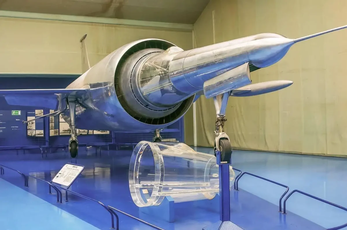
Aerospace developmentAerospace development parts.
Lightweight structural parts and precision 5-axis machining.
Prototype and development hardware for aircraft and propulsion programmes: lightweight structural parts, brackets and interface plates machined on multi-axis equipment, to your drawing and material documentation requirements.
- TYPICAL PARTS
- Structural brackets, interface plates, prototype hardware
- PRIMARY ROUTE
- 5-axis and multi-axis CNC machining
- COMMON MATERIALS
- Aluminium 7075 and 6061, titanium, stainless steel, PEEK
SPECIFICATION
APPLICATION REQUIREMENTS
What decides the design here.
Four things shape the route before a tool is selected. If any of them is unknown at enquiry, we say so instead of assuming a default.
Read the design guideFunctional datums
The features that locate the part in the assembly. The datum structure drives the setup plan and the inspection method.
Material documentation
Grade, specification and the certificate that has to accompany the material. State it at enquiry so it can be sourced with the order.
Weight and structural intent
Which sections carry load and which only close the envelope. Thin walls and deep pockets are machined differently from solid structure.
Qualification expectations
Inspection coverage, first-article reporting and any customer-specific requirements that apply before a production commitment.
PARTS WE MAKE
Parts for this application,
and the geometry that shapes them.
Workshop photographs of real geometry. Each one carries the route, what the machine has to reach, what is checked, and what you need to state on the drawing.
See more part geometry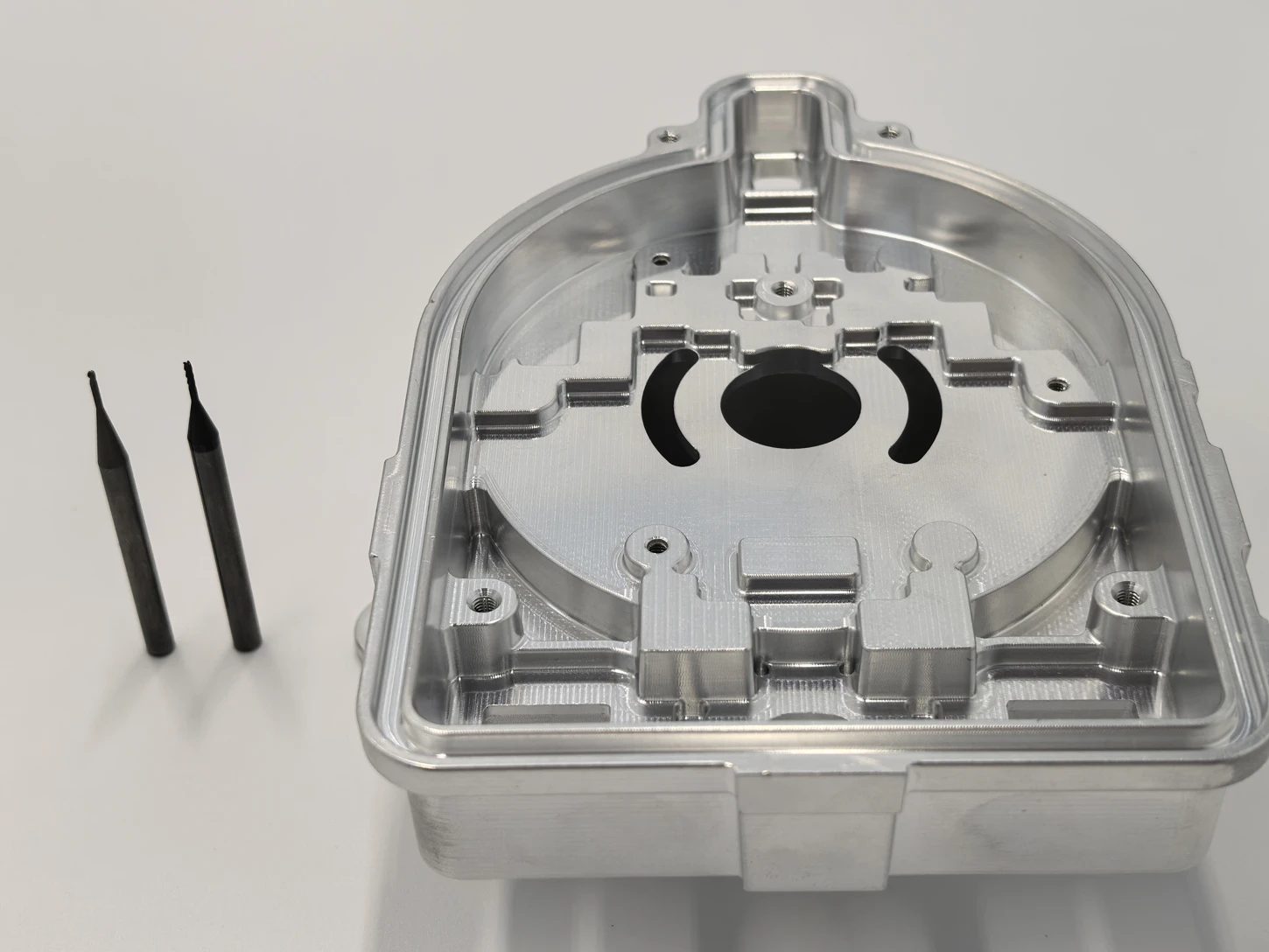
Multi-axis structural detail
Tool access to pockets at compound angles and the cutter lengths needed to reach them. Longer cutters deflect more, which is what limits how thin a wall can go.
Indicate the faces requiring a single setup and the critical wall sections.
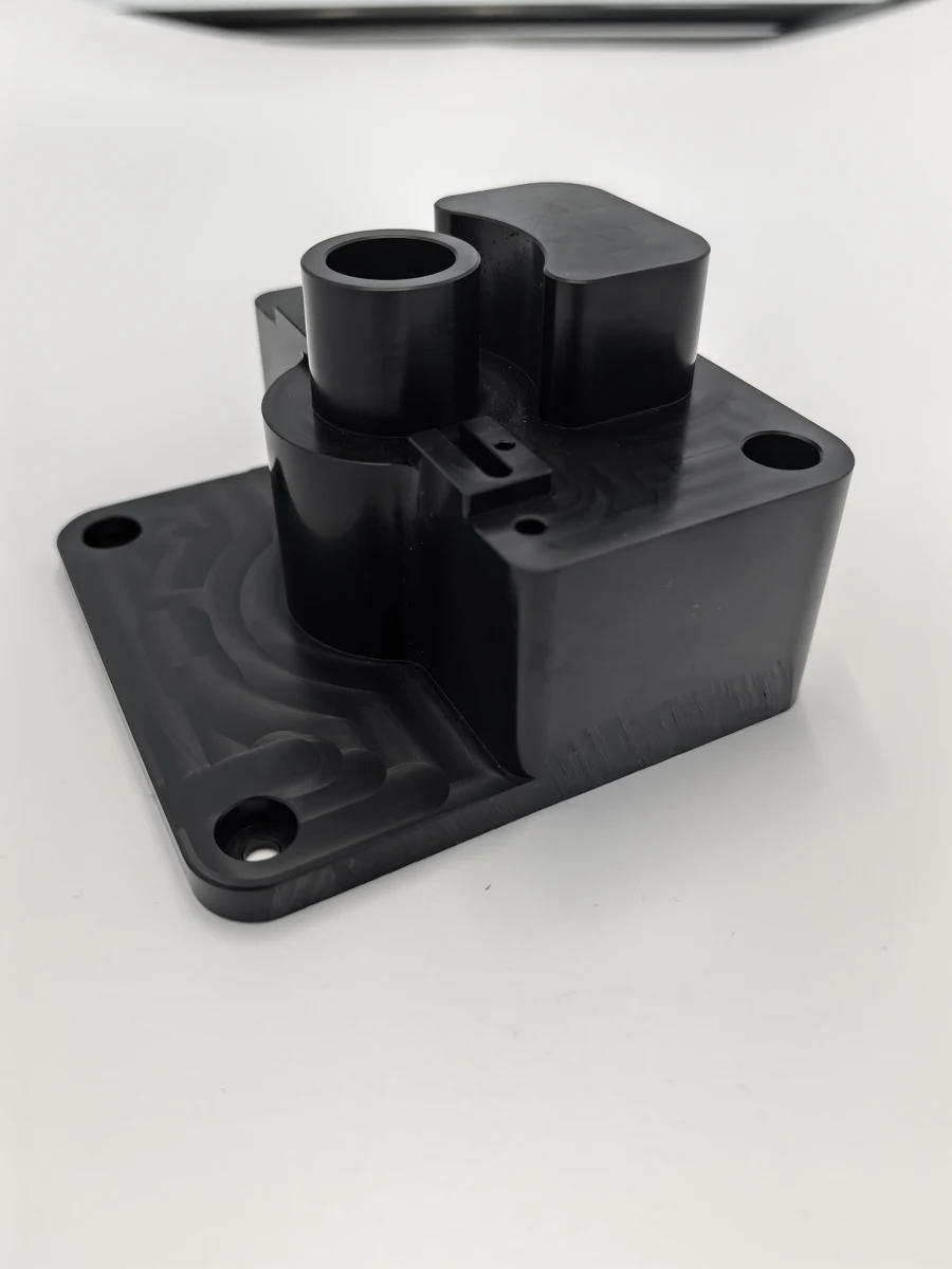
Interface plate
Hole-pattern accuracy, flatness and the relationship between the bore and the mounting face. These three decide whether the assembly bolts up without shimming.
Mark the datum faces, hole tolerances and any surfaces that must remain flat.
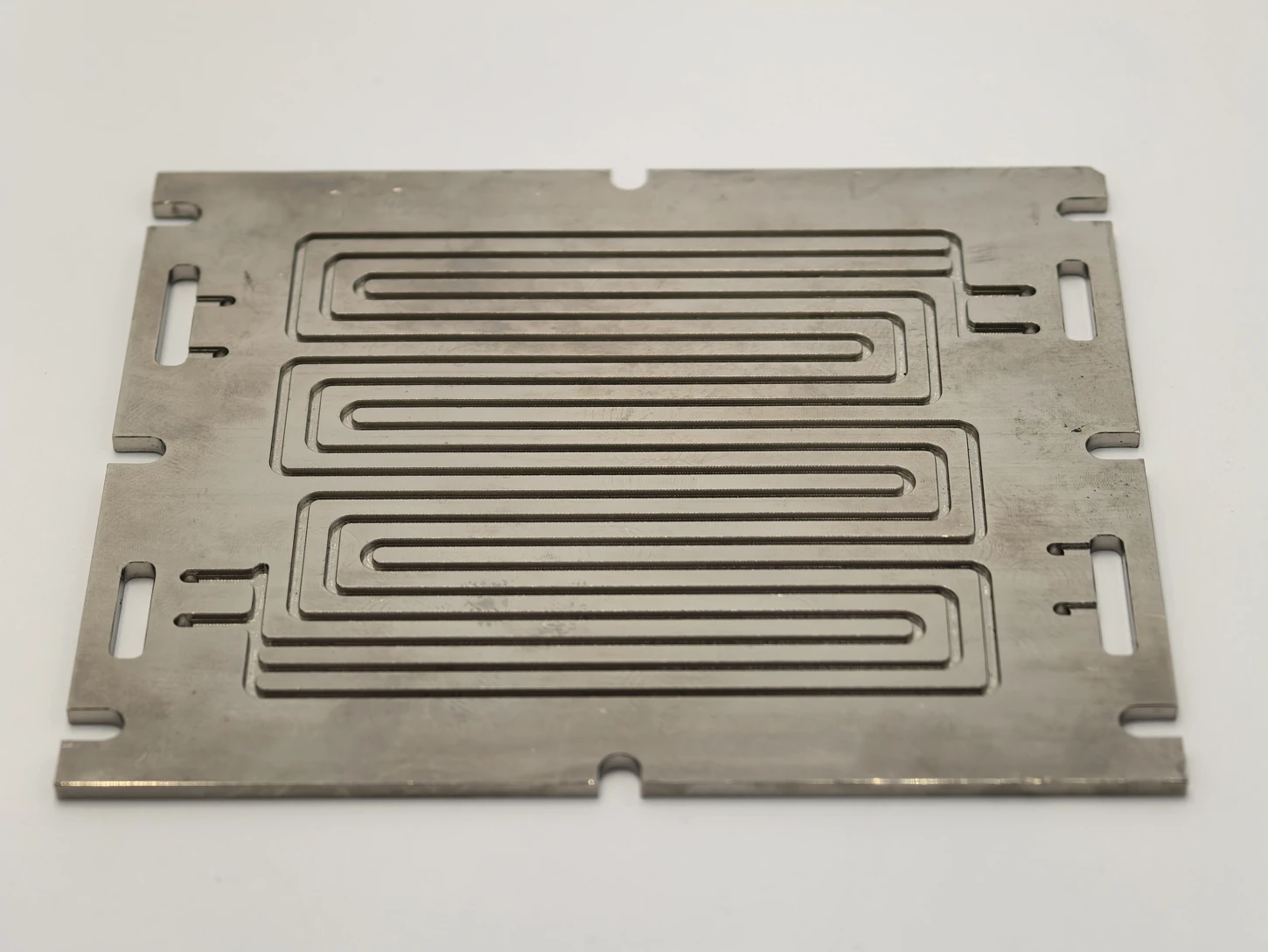
Thin-wall ribbed panel
Fine channel width against the cutter diameter, and the minimum rib that will not chatter. Thin ribs move during cutting unless the route plans for it.
State the minimum rib thickness, the channel width and whether sharp corners are required.
PROCESSES, MATERIALS AND FINISHES
The routes used for these parts.
Not every route suits every part. These are the ones that come up most for this application; the quote states the route chosen for your geometry and quantity.
All capabilitiesPROCESSES
FINISHES AND TREATMENT
Finishing changes dimensions: coating thickness, masking and any effect on a mating fit are agreed before the route is fixed, not discovered at inspection.
INSPECTION AND DOCUMENTATION
What we measure, and what we record.
The inspection scope is agreed with the order. Anything you need recorded has to be stated before machining starts, because it cannot be reconstructed afterwards.
Tolerancing standards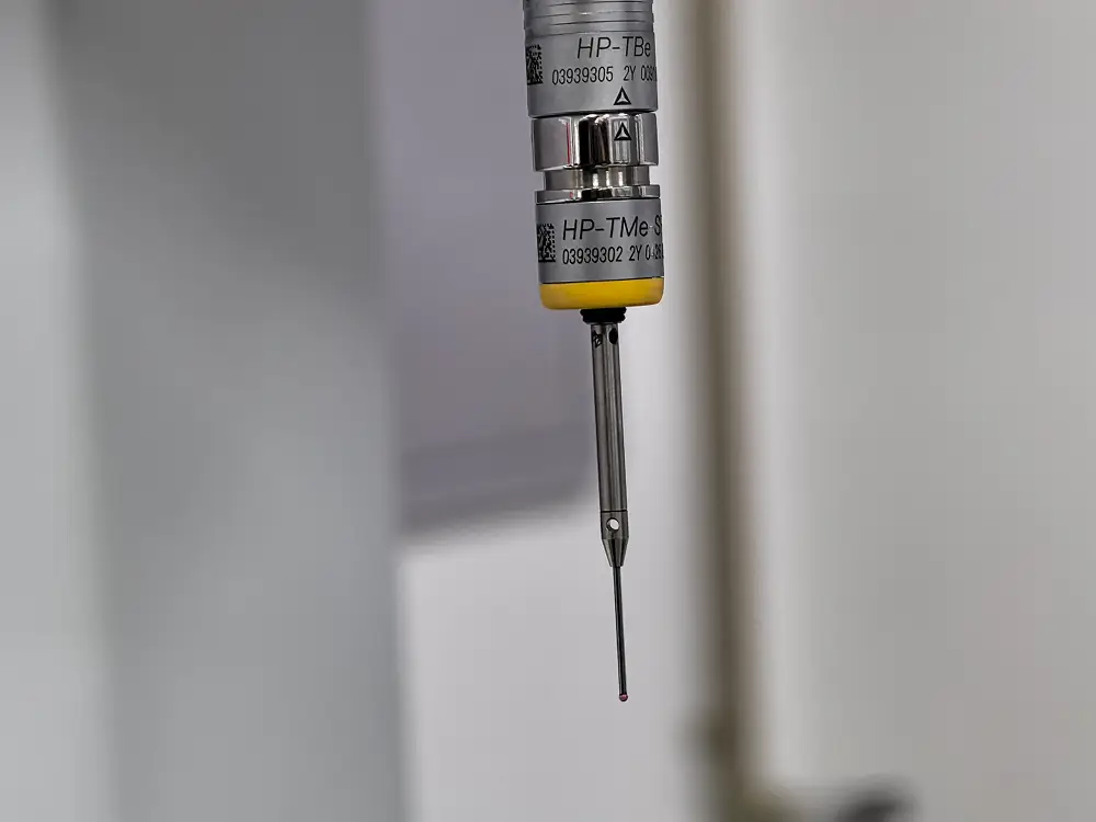
Dimensional inspection
Datums, bore sizes and mounting patterns measured against your drawing, with the method agreed before production.
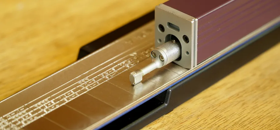
Surface roughness
Roughness measured where the drawing calls it out, on sealing, sliding and contact faces.
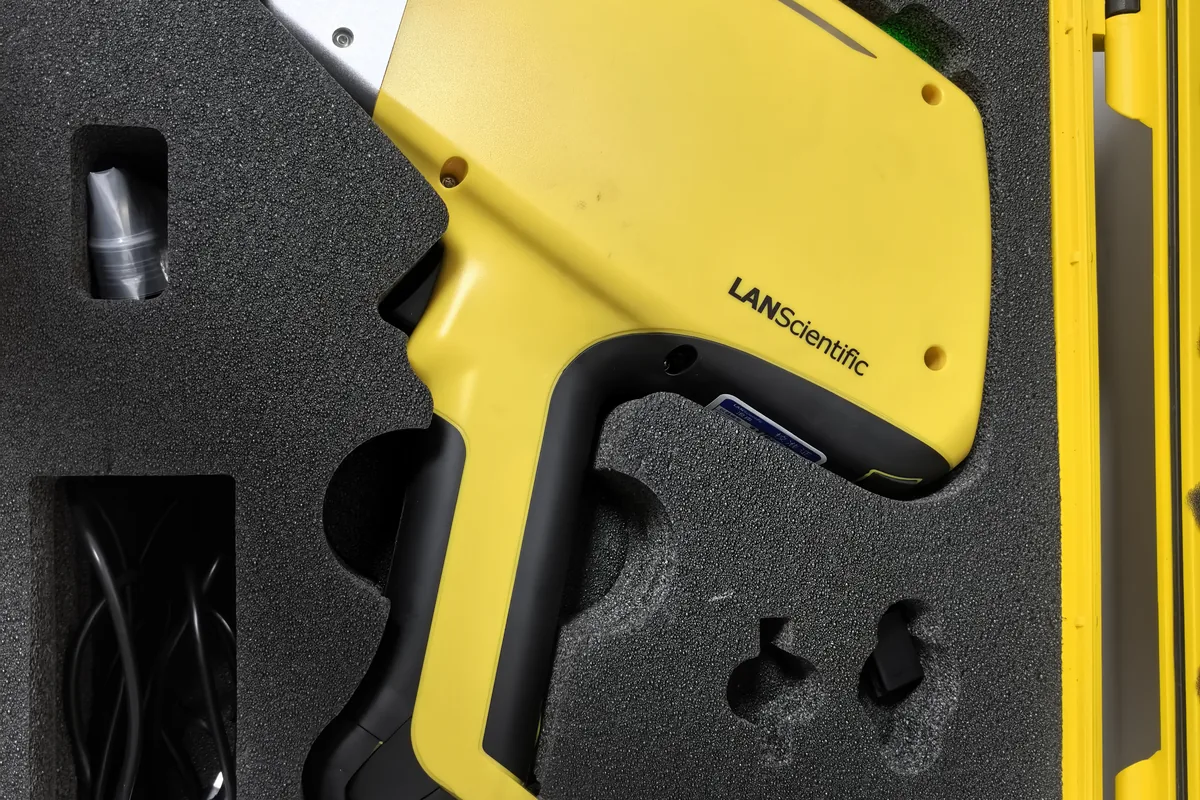
Material verification
Alloy grade checked before machining. Certificate scope is agreed with the material order, not added afterwards.
Where a programme requires verification we cannot give in-house, independent third-party testing or inspection can be arranged. The scope and the cost are agreed in the quote, not added later.
AGREED BEFORE THE ORDER STARTS
- 01Drawing revision and the datum structure it defines
- 02Material specification and the certificate that must accompany it
- 03Inspection coverage and first-article report format
- 04Deburring and edge-break requirements
- 05Identification and traceability marking, if required
- 06Packing and protection for development hardware
APPROVED CASE STUDIES
Case studies for this application.
A case study needs approved objective, process, inspection and result records. We do not publish a project until that approval exists.
Case studies are being prepared for publication.
The part photographs above are workshop images of real geometry. They show what can be made, not a completed project: material, tolerance, quantity and delivery results are published only where the customer has approved the record. Until then, the fastest way to see whether your part fits our route is an engineering review.
QUESTIONS
Aerospace questions.
The questions that come up for this application. Anything not covered here goes to an engineer.
Are you AS9100 certified?
No. We hold ISO 9001:2015 through SGS. We supply development and prototype hardware with the inspection records you specify, and we do not manufacture under an AS9100 quality system. Where your programme needs independent verification, third-party testing can be arranged and the scope agreed in the quote.
Can you supply material with full certification?
Yes where the grade is available with certification. Tell us the specification at enquiry – traceability has to be arranged with the material, not added afterwards.
Do you make flight hardware?
We make development and prototype hardware. Whether a part is releasable for flight is your programme is decision and your certification to make; we do not make that determination.
How do you hold a datum through multiple setups?
The setup plan follows the datum structure on your drawing. If a part needs several setups, we agree which features are machined together and record the sequence.
How is the lead time set?
From geometry, material sourcing and inspection scope. Certification requirements are part of that, so they need to be stated early.
START WITH YOUR DRAWING
Bring your next part
to an engineering review.
Send CAD or a drawing, quantity, material and critical requirements. We will review the manufacturing route, price and lead time.