
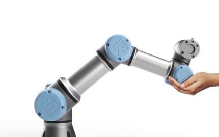
Industrial robotics reaches a new milestone
The International Federation of Robotics reported on 24 September 2026 that the operational stock of industrial robots reached approximately five million units in 2025. Its World Robotics 2026 release records more than 600,000 new installations during 2025, an 11% annual increase. The report year is 2026; the installation and operating-stock figures describe 2025.
For manufacturers, this growth makes robot selection and integration increasingly relevant. It does not mean that every handling or machining task is automatically suitable for a robot. This article updates our original 11 November 2022 coverage with current industry context, a clearer distinction between robot structures and collaborative applications, and practical considerations for CNC cells.
What an industrial robot does
An industrial robot is an automatically controlled, reprogrammable manipulator used in industrial automation. Its work can include moving a gripper, guiding a tool or positioning a part. Grabbing an object is therefore one application, rather than the defining capability of every industrial robot.
A working cell includes more than the robot arm. The controller and programming interface operate alongside the end effector, fixtures, sensors, machine interfaces and protective measures. A teach pendant is one way to program and operate a system; offline programming and other interfaces may also be used.
Compare mechanical structure separately from application
Robot architecture describes how its axes are arranged. Terms such as collaborative, desktop or machine-tending describe different aspects of a product or application and should not be treated as mutually exclusive mechanical categories.
| Structure or description | Typical manufacturing use | What to check |
|---|---|---|
| Articulated arm | Multi-direction handling, welding, finishing and CNC tending | Reach, orientation, wrist load and collision-free access |
| SCARA | Planar assembly and small-part handling | Required vertical stroke, insertion force and tool orientation |
| Cartesian or gantry | Linear transfer and loading across a defined work envelope | Travel, support structure, machine access and installation space |
| Parallel or delta | Fast handling of relatively light products | Payload, picking envelope and end-effector requirements |
| Desktop robot | Compact dispensing, screwdriving or assembly stations | The actual axis structure and process capability; size is not an architecture |
| Collaborative robot application | Tasks designed for interaction between people and robots | Application-level risk assessment, tooling, workpiece and protective measures |
These are selection starting points, not universal performance rankings. Manufacturers’ product specifications must be checked for the actual configuration and duty cycle. ABB’s published robot portfolio, for example, distinguishes articulated, SCARA and delta products for different handling and assembly requirements.
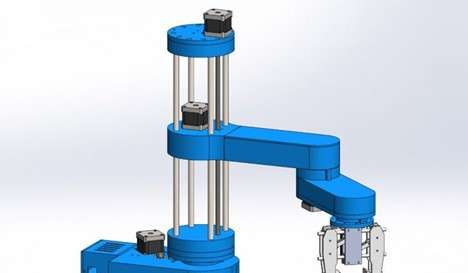
CNC machine tending is different from robotic machining
In machine tending, a robot loads and unloads a CNC machine while the machine tool performs the cutting. The integration must coordinate doors, workholding, machine status, part presence and recovery after an interruption. A successful cycle also depends on how blanks arrive and how completed parts leave the cell.
In robotic machining, the robot itself guides the cutting tool or positions the workpiece during cutting. Reach and flexibility can be useful, but structural stiffness, cutting forces and calibration affect the result. A robot’s positioning repeatability should not be treated as a promise of finished-part machining accuracy.
Robotic deburring or trimming may be practical where access and path flexibility matter. Precision bores and tightly controlled mating surfaces may still require a conventional machine tool. The process should be demonstrated on representative material and geometry before production acceptance.
Build the application around the part
- Payload: include the workpiece, gripper, adapters, sensors and any carried tools. Check the manufacturer’s wrist-load and inertia limits as well as the headline payload.
- Access: verify approach paths into the machine, fixture and inspection station. Nominal reach alone does not establish usable access.
- Gripping: review surface condition, chips, coolant, part variation and whether the grip can be confirmed before motion.
- Quality: distinguish repeatability, absolute positioning accuracy and the tolerance of the finished part. Establish how each will be verified.
- Cell performance: measure total cycle time, replenishment, changeover and recovery. Arm speed alone does not determine throughput.
- Operating environment: specify the required protection against coolant and debris, and check compatibility with the actual fluids and cleaning method.
A collaborative robot does not make the whole cell inherently safe
The 2025 editions of ISO 10218 distinguish requirements for industrial robots from requirements for robot applications and cells. ISO 10218-1 addresses the robot; ISO 10218-2 addresses integration and the application lifecycle. A collaborative label on an arm is not a substitute for evaluating the installed application.
A sharp workpiece, an exposed tool, a trapping point or an unexpected machine movement can remain hazardous. The integrator must evaluate the task and establish suitable protective measures and validation. Particular processes and environments can introduce additional hazards beyond the scope of a general robot safety standard. Applicable requirements also depend on the installation and market.
Medical and healthcare robots are separate applications and are outside the stated scope of these industrial-robot standards. The previous version’s discussion of surgery and rehabilitation as examples of CNC factory robotics has been removed.
What a systems integrator should demonstrate
A robot purchase is only part of a cell project. Ask the integrator to document the machine interface, end-effector concept, cycle assumptions, risk assessment, recovery procedure and maintenance access. A trial should include normal operation as well as realistic disturbances such as a missing blank, a failed grip or a machine stop.
For CNC operations, part variety and batch size can be as important as annual volume. A cell that performs well on one stable part family may require substantial tooling and programming changes for a high-mix workload. Compare the total operating process, including changeovers and operator intervention, against the current method.
Implications for custom robot components
Gripper fingers, adapter plates, fixtures and equipment housings need clear interfaces and acceptance criteria. Identify locating features, mounting faces, mass restrictions, surface condition and any contact with the workpiece. Material and finish choices should follow those requirements rather than a generic request for a robot-grade part.
ProleanTech can review drawings for custom CNC-machined components and robotics-related parts. Component manufacture does not establish the safety or compliance of an entire robot cell; system integration and validation remain application-level responsibilities.
Sources and editorial update
- IFR: World Robotics 2026 release, published 24 September 2026.
- ABB Robotics: published robot portfolio.
- ISO 10218-1:2025: industrial robots and ISO 10218-2:2025: industrial robot applications and cells.
Originally published 11 November 2022. Updated 23 October 2026: added the latest verified IFR release, corrected robot classification and CNC application claims, removed the unsupported forecast of more than 50% annual cobot growth, and expanded integration, quality and safety context.
← Back to all news