“Reading 2D drawings for sheet metal fabrication is similar to language translation. It requires understanding every line, symbol, and dimension to bring a design to life.”
2D drawings serve as the bedrock for manufacturing industries, acting as the blueprint for every process, including sheet metal fabrication. These technical drawings encapsulate the design intent, detailing every aspect, from dimensions and tolerances to material specifications and finish requirements. However, to fully leverage these drawings and achieve immaculate sheet metal parts, one must possess the skill to interpret them correctly.
This comprehensive guide aims to educate you on how to read 2D drawings for sheet metal fabrication, paving the way for an efficient and effective fabrication process.
Essentials of 2D Drawings in Sheet Metal Fabrication
Two-dimensional (2D) drawings are fundamental in the sheet metal fabrication sector. These drawings are graphical representations of the final product, carrying comprehensive details about dimensions, material specifics, finish types, and other attributes.
What is a 2D Drawing?
A 2D drawing is a technical blueprint used in the manufacturing industry to convey detailed information about a part or assembly. This information includes but is not limited to, part geometry, dimensions, tolerances, material specification, surface finish requirements, and assembly instructions.
They function as a universal language within the manufacturing world, ensuring seamless communication and understanding among designers, manufacturers, and quality inspectors. 2D drawings are usually drafted following certain international standards like ASME Y14.5, ISO, or DIN. If you’re preparing 2D drawings for manufacturing, accurate dimensions and tolerances are essential. Our engineering team can review your design files to help ensure they are ready for production. Feel free to contact us for technical support.
Purpose of 2D Drawings in Sheet Metal Fabrication
In the context of sheet metal fabrication, 2D drawings play a pivotal role. They not only convey the physical characteristics of the part but also contain information on specific fabrication processes like bending, punching, welding, and surface finish. Here are the core purposes of 2D drawings:
- Design Communication: They serve as a visual language, transferring design intent from the designer to the fabricator.
- Process Specification: They detail the manufacturing steps, including bending, cutting, and welding.
- Quality Assurance: They act as a reference for inspection, ensuring the final product aligns with the original design intent.
Related to: The Indispensable Role of 2D Drawings When Ordering Parts from a Manufacturer
Key Elements of 2D Drawings for Sheet Metal Fabrication
Understanding the key elements of a 2D drawing is crucial for sheet metal fabrication. This knowledge ensures accurate execution of the fabrication process, resulting in high-quality end products.
1. Dimensions and Tolerances
Dimensions indicate the size of the sheet metal part, while tolerances specify the allowable deviation from these stated dimensions. Tolerances are particularly important in sheet metal fabrication due to the inherent variability in material properties and fabrication processes. The table below lists some common dimensions and tolerance symbols:
| Symbol | Meaning |
|---|---|
| R | Radius |
| D | Diameter |
| ∅ | Diameter |
| ± | Plus/Minus Tolerance |
| 0.25/0.12 | Bilateral Tolerance |
2. Material Specifications
The material specification includes details about the type of sheet metal to be used, such as its grade, strength, and thickness. This information is vital for the fabricator to choose the right fabrication methods and tools.
3. Surface Finish Symbols and Notes
Surface finish symbols indicate the required surface texture and roughness of the final product. This information affects the choice of fabrication and finishing processes. Some common finish requirements for sheet metal parts include anodizing, powder coating, and plating. In addition, notes provide further details about finishes, treatment processes, or any special instructions for the fabricator.
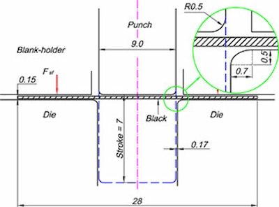
Bending and Folding Indicators in 2D Drawings
In sheet metal fabrication, bending and folding operations significantly impact a component’s shape and functionality. Therefore, clear indicators of these operations are essential in 2D drawings.
| Bend Lines and Angles | Bend Direction | Bend Radius |
|---|---|---|
| Indicate where the sheet metal should be bent or folded. | In some cases, the direction of the bend is crucial to the final component’s assembly or function. | The bend radius is the distance from the bend center to the inner surface of the material. |
| Represented as straight lines on the drawing. Along with these lines, the drawing should include the bend angles, specifying how much the material needs to be bent. | This information is generally provided with an arrow showing the inward or outward bend direction. | This parameter can affect the part’s mechanical properties, so it’s usually specified in the 2D drawing. |
Try Prolean Now!
Notations for Cutting and Punching
Cutting and punching processes form another critical aspect of sheet metal fabrication. As such, notations for these processes are integral components of 2D drawings.
- Cut Lines and Patterns
Cut lines are critical to the manufacturing of sheet metal parts. They represent the paths along which the sheet metal will be cut and can indicate straight cuts, curve cuts, or complex geometric patterns. These lines are crucial to ensuring that the part is cut to the exact specifications required for its application.
- Punch Marks
Punch marks are also important in sheet metal manufacturing. They represent the locations where holes or other cut-out shapes will be created in the sheet metal. These marks are usually indicated by circles (for holes) or other geometric shapes and the dimensions are included to ensure that the part is manufactured to the exact specifications required.
- Edge Conditions
The edge conditions of sheet metal parts are also critical to their performance and safety. The need for deburring or edge rounding after cutting and punching processes is often noted on the drawing. These notes ensure that the final product meets the required safety and performance standards. Additionally, the aesthetics of the part are also taken into consideration, as any rough edges or burrs can detract from the part’s appearance.
Surface Finish Specifications in 2D Drawings
Surface finish can significantly impact a sheet metal part’s function, aesthetics, and durability, so it’s usually specified in the 2D drawing.
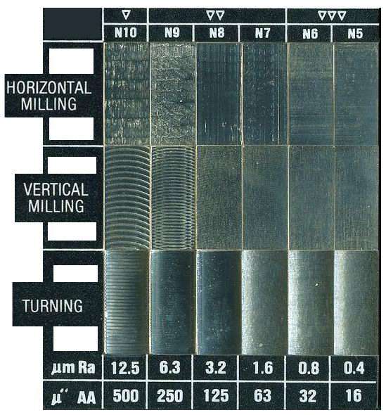
- Surface Roughness: Surface roughness is a measure of the texture of the surface. It is usually represented by the Ra (Roughness Average) value on the 2D drawing. A smaller Ra value means a smoother surface.
- Surface Treatment: The 2D drawing might specify surface treatments such as painting, anodizing, or plating that the part should undergo after fabrication. This can affect the part’s look, corrosion resistance, and durability.
- Hardness and Material Properties: Some 2D drawings will also provide specifications regarding the hardness or other material properties desired in the finished part. This is particularly important for parts that will be subjected to significant wear and tear or harsh environments.
Dimensioning in 2D Drawings for Sheet Metal Fabrication
Accurate dimensioning is crucial for successful sheet metal fabrication. Here are some common elements related to dimensioning that you’ll find in 2D drawings.
1. Basic Dimensions
Basic Dimensions are the fundamental measurements of a part, typically including its length, width, and height. They are one of the first things a fabricator will check when reading a 2D drawing. These measurements are crucial in determining the part’s overall shape and size, as well as understanding how it will fit with other parts in an assembly. Additionally, fabricators may use these dimensions to calculate the material needed to create the part.
2. Tolerances
Tolerances are important specifications that define the acceptable range of variation from the basic dimensions. In sheet metal fabrication, tight tolerances may be necessary for parts that need to fit together precisely. For example, if a part has a tolerance of +/- 0.001 inches, it means that the actual size of the part can vary by up to 0.001 inches from the specified dimension. Tolerances are crucial in ensuring that parts fit together correctly and perform their intended function.
3. Hole and Feature Locations
The locations of holes and other features are usually specified relative to one or more datums (reference points) on the part. This helps ensure that these features are fabricated in the correct positions. Additionally, fabricators may use these datums to determine other critical dimensions of the part. For example, if a hole is located 2 inches from a particular datum, the fabricator can use this information to determine the precise location of other features on the part.
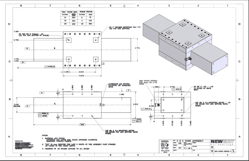
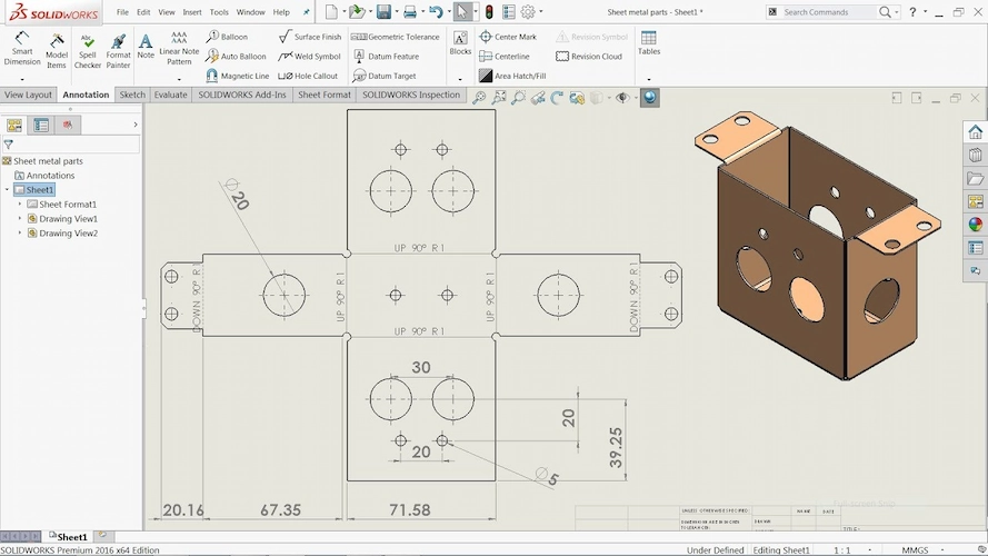
2D drawing dimensioning example
Sheet Metal Drawing Standards
Standards serve as a tool to bring uniformity in sheet metal drawings across different countries and regions. They also set the benchmark for quality checks of fabrication parts. International Standard Organization( ISO) standards are most common in sheet Manufacturing, like in every other process. However, there are other standards also, such as The American Society for Testing and Materials (ASTM) standards.
Sheet Metal Drawing: ISO Standards
These are the globally recognized standards that set international benchmarks across various industries to prepare a perfect technical drawing. In sheet metal, adhering to ISO standards is essential for ensuring that products meet rigorous international quality and performance criteria.
Here’s a list of different ISO standards commonly used in sheet metal drawings:
- ISO 2768-1: It is a general tolerance for linear and angular dimensions without individual tolerance indications.
- ISO 7438: Pertains to the bending test for metallic materials.
- ISO 9013: It defines thermal cutting classification for CNC Laser Cutting and Plasma cutting concerning geometrical product specifications and quality tolerances.
- ISO 2553: It provides symbols and indications for sheet metal welding.
- ISO 10721-2: This ISO provides guidelines for the fabrication and erection of steelwork.
- ISO 9018: Determines destructive tests on welds in metallic materials, specifically bend tests.
- ISO 3834: Series of standards providing quality requirements for fusion welding of metallic materials.
- ISO 10012: Establishes requirements for the processes of measurement management systems.
These ISO standards ensure accurate sheet metal fabrication and consistent quality. If your design files are ready, you can get a quote for custom sheet metal manufacturing, and our engineers will review your drawings for production feasibility.
Try Prolean Now!
What are Sheet Metal CAD Drawings?
Sheet Metal CAD Drawings are digital blueprints containing precise and detailed representations of the final product or structures. Specialized software like AutoCAD and SolidWorks are used to create these drawings. CAD drawings include all necessary specifications, such as dimensions, materials, and manufacturing processes.
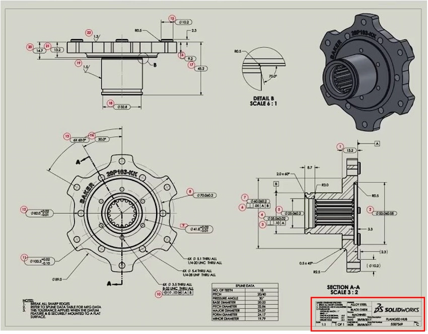
2D CAD drawing of sheet metal part
Furthermore, the integration of CAD in sheet metal fabrication marks a significant advancement in manufacturing technology. The complex geometries and intricate details can be easily manipulated and optimized for fabrication using CAD drawings. They support various fabrication processes like sheet metal cutting, bending, and assembling. Overall, a sheet metal CAD drawing streamlines the fabrication workflows and improves overall efficiency.
Related: The Complete Guide to CNC Files and CAD Formats
How to Read Sheet Metal Drawings? Step by Step
Reading a sheet metal drawing involves identifying the details of the design of sheet metal parts, such as dimensions, geometry, material specifications, and any special requirements. Meanwhile, detailing this information requires a series of steps, each focusing on different aspects of the drawing.
 How to read a sheet metal 2d drawing
Let’s discuss these steps of how to read sheet metal drawings in brief:
1. Start with the Title Block
Look at the bottom or right corner of the drawing for the title block. It contains essential information about the drawing, such as:
- The part name
- Part number
- Material specifications
- Drawing number
- Scale
- Nname designer or company
The title block might also include the date of creation or modification and approval signatures. Basically, it sets the context for the rest of the drawing and is the starting point for understanding the part specifications.
2. Examine the Drawing Scale
Sheet metal drawings are often scaled down to fit on the paper. So, identify the scale of the drawing. The scale helps in understanding the true dimensions and measurements of the part. Additionally, thickness could be expressed in sheet metal gauges. On the other hand, neglecting the scale can lead to misinterpretation of sizes and an inaccurate fabrication of the part.
3. Interpret Dimensions and Tolerances
Dimensions are annotated in lines and arrows, indicating the length, width, height, and other relevant measurements. Alongside dimensions, you can see tolerance variance in each dimension. Tolerances are essential for ensuring proper fit and function in assemblies.
4. Analyze Views and Sections
The sheet metal engineering drawing contains multiple views: front, top, side, and sometimes sectional views. Subsequently, each view provides information about the part from different angles. Sectional views provide information on internal features, like bends or internal cutouts. Additionally, you can correlate each view with each other to get a complete picture in your head. If you have sheet metal CAD drawing, asses the 3D views of the design.
5. Decode Symbols and Notations
Symbols and notations indicate specific fabrication processes or requirements. These might include sheet metal welding symbols, bend lines, grain direction, or surface finish symbols. So, familiarize yourself with these symbols and choose the specific operations required for the sheet metal fabrication.
6. Look for Special Features or Instructions
Features like holes, notches, tabs, or embossments are typical in sheet metal parts. A sheet metal fabrication drawing contains t information on such features and special instructions for fabrication. Instructions might include details on bending angles, hole patterns, or hardware insertions.
7. Review the Bill of Materials (BOM)
The BOM lists all the materials, components, tools, and hardware required for the fabrication. For example, numbers, descriptions, quantities, and material specifications. The BOM is essential when the component to be fabricated is part of a larger assembly.
8. Surface Finishing Instructions
Finishing processes such as painting, plating, or anodizing is often specified in sheet metal drawings. Ensure you understand the type of finish required and any specific color codes or standards.
9. Confirm Compliance with Standards
Lastly, check if the drawing specifies compliance with industry or international standards, like ISO or ASTM. It is critical to adhere to these standards to ensure that the part meets quality, safety, and regulatory requirements.
Summing Up
Reading 2D drawings is an essential skill for any sheet metal fabricator. By understanding how these drawings represent various aspects of the fabrication process, fabricators can ensure that the finished parts meet all the design requirements. Whether you’re a fabricator or a customer, being familiar with these concepts can help you communicate more effectively about your fabrication needs.
Prolean’s Sheet Metal Fabrication Services rely heavily on the precision and detail of 2D drawings. By using state-of-the-art technology and CAD software, our experts can accurately interpret these drawings to fabricate high-quality sheet metal parts. Our commitment to quality, efficiency, and customer satisfaction makes it a trusted partner for all your sheet metal fabrication needs.
Read more:
- China Sheet Metal Fabrication: Affordable & High-Quality Solutions
- Stainless Steel Sheet Metal Fabrication: Process and Applications
FAQs
Why are 2D drawings still used in sheet metal fabrication when 3D modeling is available?
While 3D modeling is an invaluable tool in modern manufacturing, 2D drawings are still essential for conveying information efficiently about dimensions, tolerances, and fabrication processes. They also serve as a universal language that any fabricator can understand, regardless of what CAD software they use.
What software is used to create 2D drawings for sheet metal fabrication?
Various CAD software can be used to create 2D drawings, including AutoCAD, SolidWorks, and more. The choice of software often depends on the complexity of the parts and the specific needs of the manufacturer.
What should I do if I can’t understand a symbol or notation on a 2D drawing?
If you encounter a symbol or notation that you don’t understand, it’s important to seek clarification rather than make assumptions. You can consult an engineering drawing handbook or ask the person who provided the drawing.
Does Prolean offer services to help create 2D drawings for sheet metal fabrication?
Yes, Prolean’s team of experts can assist you in creating detailed, accurate 2D drawings for your sheet metal fabrication projects. Contact us for more information.
References
- https://www.eng-tips.com/viewthread.cfm?qid=308842
- https://www.truecadd.com/sheet-metal-design.php
0 Comments