“A perfect technical drawing is a clear, precise blueprint; it guides the manufacturer or operator with the designer’s vision, turning complex ideas into tangible realities.”
A minor error in a technical drawing can lead to production delays and rejected parts in high-precision manufacturing.
Technical drawings are the means of communication between designers, operators, manufacturers, and suppliers. They contain a detailed blueprint of a part or product, including tolerances, finishes, and other key design elements. A technical drawing could be in 2D or 3D form, mostly in computer-aided design (CAD format) software. Since a technical drawing is base of any manufacturing, let’s learn how to prepare a perfect technical drawing.
This article will guide you in the elements and features of perfect drawing, step-wise elaboration of perfect drawing making, and GD & T symbols.
Why We Need Technical Drawings?
Firstly, technical drawings serve as the foundational language in manufacturing. These are crucial communication tools, bridging the gap between a designer’s idea and a manufacturer’s execution. These drawings convey detailed instructions, eliminating guesswork in the production process. A technical or manufacturing drawing details dimensions, materials, and procedures, ensuring everyone involved understands the exact specifications. So, it eliminates even the slight misunderstanding in the manufacturing process, especially in CNC machining and sheet metal fabrication.
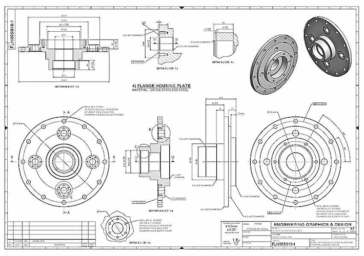
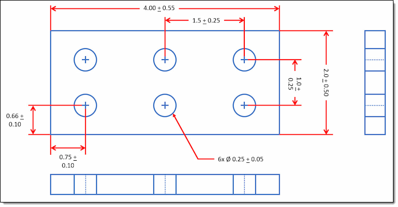
2D technical drawing of a flange housing plate
Secondly, technical drawings are essential for maintaining quality and consistency. They act as a benchmark throughout the manufacturing process. We can only accurately replicate parts or products by adhering to the drawing specifications, ensuring uniformity across multiple batches. This consistency is crucial for industries like automotive and aerospace, where precision is non-negotiable. Moreover, technical drawings facilitate quality control checks. They provide a reference point against the final product.
Thirdly, technical drawings are indispensable in troubleshooting and future modifications. They are a comprehensive record of the design and manufacturing process. If a problem arises during production or after the product, drawings can help identify the issue’s source quickly. They also simplify the process of making improvements or modifications to the product.
Two Types of Technical Drawings
These drawings vary in complexity and style, each suited to different stages of the manufacturing process. Broadly, there are two types of technical drawings: 2D (two-dimensional) and 3D (three-dimensional). Both drawings contain unique features, uses, and benefits.
2D Technical Drawing
2D technical drawings are the traditional form of drafting and are still widely used today, visualizing precise measurements and a clear picture of the object’s geometry. These drawings are created on flat surfaces and consist of lines, dimensions, and notations. Subsequently, 2D drawings effectively communicate the layout, dimensions, and parts assembly.
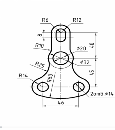
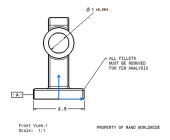
Example of a 2D drawing
Furthermore, 2D technical drawings are crucial for quality control and inspection processes. They serve as a guide to ensure that each manufactured part adheres to the specified dimensions and tolerances. For example, it’s critical in precision applications, such as CNC machining and carpentry. Additionally, they are easier to standardize and easily understandable without specialized tools or software. This universality makes them ideal for communicating across different departments and with external manufacturers. So, 2D drawings have an indispensable role when ordering parts from manufacturers.
However, 2D drawings have limitations in visualizing complex shapes and assemblies. They require multiple views – such as top, front, and side – to fully convey an object’s shape and dimensions. Therefore, it can sometimes lead to confusion or misinterpretation if not done correctly.
3D Technical Drawing
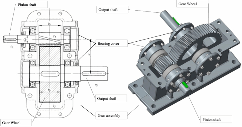
3D technical drawings represent a significant advancement in the field of engineering drafting. These drawings provide a more realistic and detailed view of objects with a better presentation of their form and function. Firstly, 3D allows a comprehensive view of an object from any angle. This capability is invaluable for visualizing complex parts and assemblies. Additionally, 3D models or drawings help to create realistic renderings and animations.
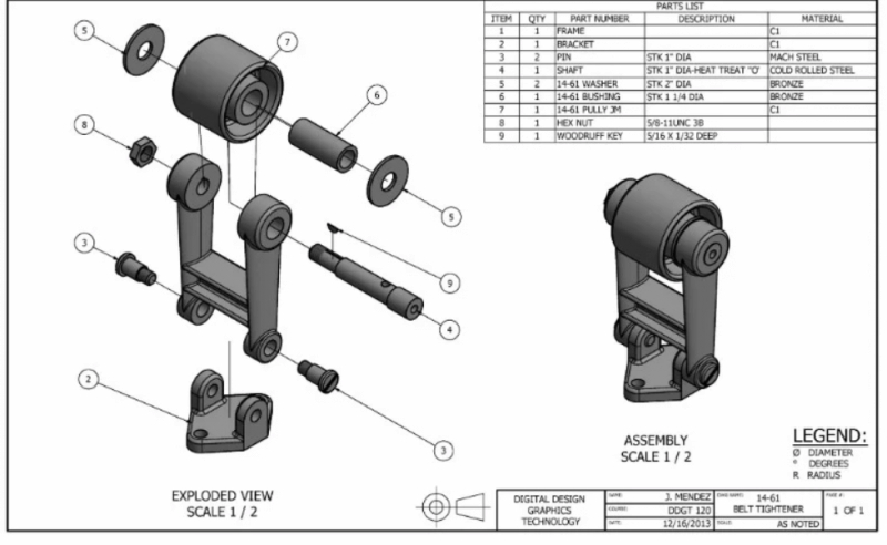
3D technical drawing example
Secondly, 3D drawings are integral to modern manufacturing processes, such as CNC machining and 3D printing. 3D models are the data source that can be directly fed into manufacturing machines. This direct translation from design to production reduces the chances of errors and speeds up the time to market. Moreover, 3D drawings are simple to modify. Designers in comparison of 2D vs 3D drawings. 3D can quickly make changes and see their impact, leading to more efficient and effective product development.
However, creating 3D technical drawings requires more advanced skills and software than 2D, which can be a barrier for smaller companies or individuals. Additionally, 3D models can be more data-intensive, requiring more storage and processing power. Despite these challenges, the benefits of 3D technical drawings are significant, particularly for complex projects where precision and detail are essential.
At this stage, many manufacturers move from research to execution. If you’re planning to produce parts, contact us to discuss your requirements with precision manufacturing experts.
Related: A Guide to Interpreting 3D Drawings for CNC Machining
Try Prolean Now!
Elements of a Perfect Technical Drawing
A perfect technical drawing is not just a representation of an object or structure; it’s a comprehensive communication tool in manufacturing. The elements of a perfect drawing are clarity, accuracy, dimensioning, annotations, scale, standard conventions, and visual representation.
Now, let’s understand in detail how these elements make a technical drawing perfect.
1. Clarity
Clarity in technical drawings ensures that every element is understandable at a glance. For example, a technical drawing of a mechanical part should have well-spaced, distinct lines indicating the edges and contours of the part.
![]()
Clear technical drawing of a mechanical bolt
Moreover, annotations and labels should be in readable font size and style, avoiding any overlap with lines or other text. For instance, if the drawing includes a bolt, its position, orientation, and type should be unambiguously clear without crowding the drawing.
- Accuracy
Accuracy is about the precise representation of dimensions and geometry. For instance, if a technical drawing is of a gear, each tooth’s dimensions, angle, and spacing must be exactly as they should be in the actual gear. A discrepancy as minor as a millimeter can lead to the gear not fitting or functioning correctly.
- Dimensioning
Effective dimensioning involves marked and easy-to-read measurements. For example, dimensions should indicate the length of its sides, the diameter of the holes, and the distances between these holes in a drawing of a bracket.
Dimensioning with proper GD&T
These measurements are placed outside the main drawing area, with dimension lines pointing to the exact measuring feature. In circular components, radial dimensions are used, while arc lengths are for curved surfaces.
- Annotations
Annotations refer to additional details in a technical drawing. This kind of specific information ensures that the manufacturing or construction process adheres closely to the design specifications.
Annotation in technical drawing
For instance, in a drawing of a steel beam, annotations might specify the grade of steel, the type of finish required, and any heat treatment it must undergo. Furthermore, If the beam needs welding to join with another component, the weld type, location, and dimensions will be annotated.
- Scale
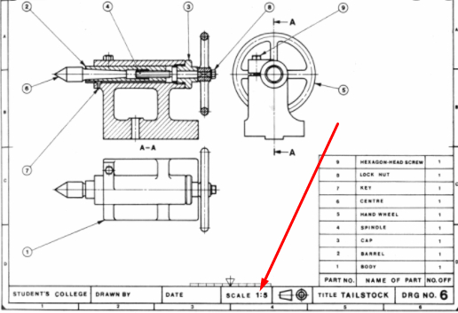
Scaling in technical drawing
The scale helps to understand the size of the object in the drawing. For example, a technical drawing of an automotive part might use a scale of 1:10, meaning 1 cm on the drawing equals 10 cm in real life. This is often indicated in the title block of the drawing.
- Standard Conventions
Using standard conventions makes a technical drawing universally understandable. For example, using a dashed line to represent hidden edges or a specific symbol to indicate a welding point aligns with standard practices understood across the industry.
These conventions might also include specific projection methods, such as first-angle or third-angle projection, often mentioned in the drawing.
- Visual Representation
The visual representation is the last element of a perfect technical drawing. It involves selecting the best views and methods to depict the object. An orthographic projection might be used for a simple machine part, showing it from the top, front, and side.
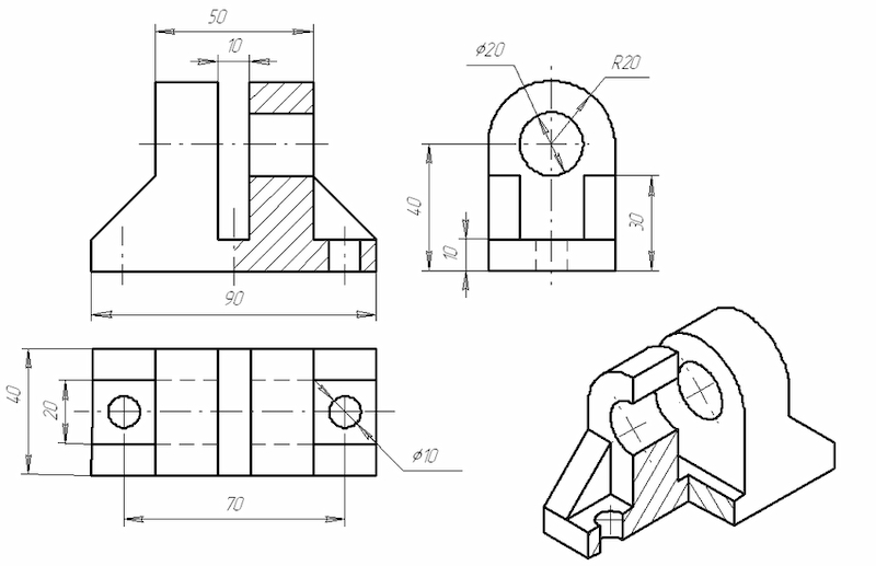
Technical drawing and its visual representation
On the other hand, an isometric view is suitable to give a three-dimensional sense automotive block engine. The choice of views should reveal all necessary details about the object’s shape and features, aiding in its accurate construction or manufacture.
Typical Steps to Create a Perfect Technical Drawing
The process of creating a perfect technical drawing is thorough and detail-oriented. Each step builds upon the previous one, culminating in a precise and informative document that effectively communicates the specifics of a design.
The following are the steps involved in the preparation of a perfect technical drawing:
Step 1: Understanding Project Requirements
The first step in creating a technical drawing is thoroughly understanding project requirements. It involves consulting with engineers, designers, or clients to identify the purpose, functionalities, and other requirements.
For example, if the drawing is for a machine part, the drafter needs to know its role in the machine, the stresses it will endure, and any size or material constraints.
Step 2: Gather Necessary Information
Once the requirements are understood, the next step is gathering all necessary information. Next, collect technical specifications, measurements, and any existing sketches or CAD files.
For instance, a shaft drawing might involve shaft standards, diameter, length, special features, necessary material properties, and finish quality. This information forms the foundation of the technical drawing and ensures that every detail in the drawing includes accurate and up-to-date data.
Step 3: Selecting Appropriate Tools and Software
CAD technical drawing
Traditional drafting tools like pencils, rulers, and drawing tables may suffice for a simple project like brackets. In contrast, CAD software is essential for more complex or 3D designs. The choice depends on the complexity of the project, the required precision, and the designer’s proficiency. However, CAD software offers advantages in precision, ease of modification, and compatibility with other software.
Step 4: Create a Rough Sketch
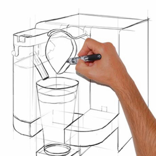
Rough sketching of a technical drawing
The actual drawing process begins with a rough sketch, an initial object focusing on its basic shape and layout. The rough sketch can be used as a conceptual guide to visualize the final product. For example, a rough sketch of a mechanical part would outline its general shape, components, and arrangement. Furthermore, a sketch doesn’t have to be accurate but should capture the essential features and proportions of the object.
Step 5: Refining Into a Detailed Drawing
After the rough sketch, the next step is refining it into a detailed drawing. It involves transforming the initial sketches into precise lines and shapes, following the gathered specifications. Here, the drafter adds details like dimensions, angles, and curves.
Step 6: Adding Dimensions and Annotations
Adding dimensions and annotations includes specifying the size, location, and quantity of each drawing element. Dimensions must be accurate and marked to avoid ambiguity during manufacturing or fabrication. Annotations provide additional information like material specifications, surface finishes, and tolerances. For example, in a gear drawing, annotations would specify the type of material, gear teeth specifications, and surface treatment requirements.
Step 7: Reviewing and Revising the Drawing
The final step is reviewing and revising the drawing. Check the drawing for accuracy, completeness, and compliance with relevant standards. It may require several iterations to ensure every aspect of the drawing is correct. Incorporate feedback from engineers or clients in this stage.
For instance, a technical drawing of a complex machinery part might need revisions to enhance clarity or to adjust dimensions based on new inputs.
Step 8: Finalizing and Documentation
Once the drawing has been reviewed and revised, the final step is to finalize and document it. Clean up the drawing, ensure all elements are correctly aligned, and that the drawing is error-free. Moreover, Save your perfect technical drawing in an appropriate format, such as STEP file viewer.
Click here to download: The Basics of Technical Drawing
Try Prolean Now!
GD & T Symbols for Perfect Technical Drawings
Geometric Dimensioning and Tolerancing (GD&T) is a system for defining and communicating engineering tolerances. It uses symbolic language on technical drawings. It is another essential part of perfect technical drawings as it specifies the nominal geometry and its allowable variation.
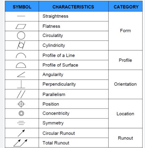
GD & T symbols for perfect technical drawings
Moreover. The GD & T symbols accurately define the parts and assemblies’ geometry.
- Straightness – A straight line symbol indicating that an element must be straight within specified tolerances.
- Flatness – A parallelogram symbol denoting that a surface must be flat within specified limits.
- Circularity – A circle symbol indicating that an element must be round within specified tolerances.
- Cylindricity – Two concentric circles symbolizing that a feature must be cylindrical within specified limits.
- Profile of a Line – A line with two arcs at either end and a line through it, meaning the feature’s profile must be within the line tolerance specified.
- Profile of a Surface – A line with two arcs at either end indicating that the entire surface must be within the tolerance zone defined by the profile.
- Angularity – An angle with a line through it, specifying that a feature must be at the exact angle to a datum within specified tolerances.
- Perpendicularity – A square on its point intersected by a line, denoting that a feature must be 90 degrees to a datum within specified limits.
- Parallelism – Two parallel lines, meaning a feature must be parallel to a datum within specified tolerances.
- Position – A circle bisected by two lines at right angles, indicating the exact positioning of a feature relative to a datum.
- Concentricity – A coaxial symbol represented by two concentric circles, meaning the median points of all diametrically opposed elements must be within a tolerance zone.
- Symmetry – A triangle with a vertical line through it, indicating that elements must be symmetrical about a datum plane within specified tolerances.
- Circular Runout – Two arrows pointing to a circle, specifying that when rotating a feature, its surface must stay within the circular runout tolerance zone.
- Total Runout – Two arrows around a slanted line next to a circle indicate that the entire feature must stay within the total runout tolerance zone when the part is rotated.
Send us your Technical Drawing for Manufacturing!
At Prolan, your technical drawings are the blueprint for precision. As a China-based manufacturing powerhouse, we specialize in transforming your detailed designs into high-quality parts and products. Our process integrates advanced CNC machining and sheet metal fabrication services, ensuring your concepts materialize with exceptional accuracy.
Our manufacturing experts and advanced equipment facilities work together to convert your technical drawings into tangible, functional components. Trust us to bring your most intricate designs to life with unmatched skill and precision. So, we invite you to submit your technical drawing and request a quote today. Experience the seamless transition from paper to manufacturing.
Summing Up
Technical drawings are the base to convert the concept into concrete, serving as an indispensable roadmap in manufacturing. They are the language through which a design is communicated and transformed into reality with processes like CNC machining, CNC laser cutting, and sheet metal fabrication.
The precision and clarity embedded in a technical drawing underpin the manufacturing process, enabling engineers to craft products with exactitude. A perfect technical drawing upholds the integrity of the manufacturing process by setting a consistent quality standard. Overall, it is a benchmark against which every product is measured, from rapid prototyping to large-volume production.
Read more:
FAQs
Why are technical drawings essential in manufacturing?
Technical drawings are essential because they serve as a detailed guide for manufacturers to create precise parts, ensuring that the final product meets the design specifications.
How do technical drawings improve communication?
They provide a universal language that conveys the designer’s intent to the manufacturing team, which is critical for accurately translating designs into physical products.
What are the five elements of technical drawing?
Technical drawings are based on line quality, scaling, views and projections, dimensioning, and annotations and symbols. Each element ensures clarity and precision in the final representation of the design.
How can I be perfect in engineering drawing?
You can apply industry standards, utilize the right tools effectively, seek and act on feedback, and understand real-world applications to inform your designs.
Do technical drawings help with quality control?
Yes, they establish benchmarks for quality and consistency, which are vital for quality control checks and ensuring that each part meets stringent industry standards.
What if changes need to be made to a manufactured part?
Technical drawings are invaluable for making modifications. They serve as a comprehensive record that can be referred to when changes are needed or when troubleshooting issues.
Resources
- Bello, R. S. (2012). Technical Drawing Presentation and Practice. CreateSpace Publication. Retrieved from https://www.researchgate.net/publication/275642
- CNCCookbook. (2023). GD&T Symbols Reference Chart. Retrieved from https://www.cnccookbook.com/gdt-symbols/

0 Comments