In the fascinating realm of CNC machining, understanding and interpreting 2D drawings is an absolute necessity. These drawings act as a vital conduit for communication between the design engineer and the CNC machinist, meticulously guiding the transformation process of raw material into a final product of exact specifications. As intricate and complex as they may appear at first glance, 2D drawings distill the essence of the desired product into a visual language understood universally within the manufacturing industry. With the proper guidance and comprehension, reading these drawings can become a simplified process.
This article aims to demystify the art of reading and interpreting 2D drawings for CNC machining, dissecting the common elements and conventions you’ll encounter in your manufacturing journey.
The Basics of 2D Drawings for CNC Machining
2D drawings, also known as blueprints, provide a comprehensive plan for the final product. They incorporate all the necessary information, such as dimensions, tolerances, material type, surface finish, and any additional details relevant to the manufacturing process. With the prevalence of digital design and manufacturing technologies, 2D drawings have evolved, often rendered as part of 3D models, yet they still retain their importance as standalone design documentation.
The following are the critical components you need to understand when reading a 2D drawing for CNC machining:
What is the Scale?
Scale is an essential element of a 2D drawing. It offers a comparative ratio between the size of the drawing and the actual size of the part. Reading the scale correctly is crucial for maintaining accurate dimensions during machining. For example, a scale of 1:2 means the size of the object is twice that of the drawing. It’s important to note that all dimensions on a 2D drawing are typically provided in either metric (millimeters) or imperial (inches) units, depending upon the region or the client’s requirements.
Related Resource: Technical Drawing: Its Significance in Manufacturing
Deciphering the Symbols and Notations
2D drawings come filled with a variety of symbols and notations that represent different features or instructions for the part. These can range from surface finish symbols, and welding symbols to geometric dimensioning and tolerancing (GD&T) symbols. Learning to interpret these symbols is a significant part of understanding 2D drawings. For instance, a circle with a line drawn through it at a 45-degree angle is the symbol for ‘center line,’ and ‘R’ followed by a number usually represents the radius of a curve.
Common Symbols and Notations in 2D Drawings
| Symbol | Interpretation |
|---|---|
| Ø | Diameter |
| R | Radius |
| ↗ | Surface roughness |
| ⬖ | Symmetry |
| □ | Square |
Essential Components of a 2D Drawing
A 2D drawing for CNC machining typically consists of several key components, each providing specific and critical information for the machining process. Let’s delve into these components in more detail.
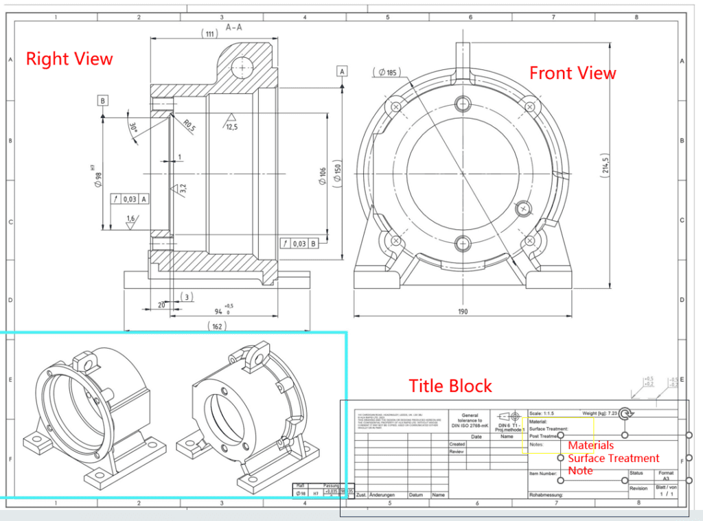
1. Title Block
Located usually in the bottom right corner of the drawing, the title block contains essential information about the drawing, such as the part name, drawing number, who drew it, the date, and the scale. This block may also contain specific notes related to the project, part revision information, material specifications, and finishing instructions.
2. Views
In a 2D drawing, multiple views are presented to provide a complete representation of the part from various angles. The most common views include:
- Front View: This is the primary view, showing the part from the front.
- Top View: Shows the part from the top, and is typically placed directly above the front view.
- Right Side View: Displays the part from the right side, typically placed to the right of the front view.
There can also be additional views such as isometric views (a 3D representation), section views (a view showing the part as if it were cut), and detail views (showing a particular feature of the part in greater detail).
3. Dimensions
Dimensions are critical to any 2D drawing as they specify the size of the part and its features. They usually consist of a dimension line, which indicates the distance measured, and an extension line, which signifies the feature’s boundaries being measured. The dimensions are typically in millimeters or inches.
4. Tolerances
Tolerances indicate the allowable variation for the dimension. In CNC machining, even the slightest variance can result in part failure, so it’s vital to adhere to these specified ranges. They may be indicated directly with the dimension or as a general tolerance noted in the title block or a separate note.
5. Surface Finish
The surface finish notation specifies the desired final appearance and texture of the part’s surface. It may require additional post-processing steps such as polishing or sanding. It’s often represented as a checkmark symbol with a value that denotes the roughness tolerance.
6. Material Specifications
The drawing should also specify the material from which the part is to be made. This could include the specific alloy, grade, or type of plastic. Material properties can significantly affect the machining process and the part’s final characteristics, making this a crucial piece of information.
7. Notes
Notes are used to convey additional information not covered elsewhere in the drawing. These could include specific machining instructions, secondary operations like heat treatment or plating, or special packaging instructions.
Try Prolean Now!
Symbols and Notations in 2D Drawings
In 2D drawings, specific symbols, and notations are used to convey a plethora of information concisely. Gaining fluency in these symbols is crucial to correctly interpreting the drawing.
| Category | Description | Symbol |
|---|---|---|
| Dimension Lines and Leader Lines | Display the length, width, and depth of a part or its specific feature. | Arrow at the ends of the line with the dimension value written above the line for dimension lines and an arrow pointing towards the part feature with a description or specification written alongside the line for leader lines. |
| Datum Symbols | Reference point, line, or plane from which the dimensions are measured. | A square symbol or a circle with a letter inside that corresponds to the datum reference frame (DRF). |
| Feature Control Frames | Define geometric tolerances in the drawing. | Contains information on the type of geometric control, the datum references, and the tolerance value. |
| Surface Finish Symbols | Denote the texture and final appearance of a surface. | The checkmark-like symbol with a numerical value indicates the surface roughness tolerance. |
The Role of Software in Reading 2D Drawings
Today, technology plays an invaluable role in reading and creating 2D drawings for CNC machining.
- Computer-Aided Design (CAD) Software; CAD software enables the creation of precise 2D drawings and 3D models of parts. These programs not only aid in the design phase but also facilitate the reading and interpretation of the drawings. Some common CAD software includes AutoCAD, SolidWorks, and Fusion 360.
- Computer-Aided Manufacturing (CAM) Software: Once a 2D drawing is completed, CAM software translates it into a language that the CNC machine understands—G-code. By doing so, it bridges the gap between the drawing and the actual machining process.
- Viewing and Markup Tools: Special software tools allow you to view and annotate 2D drawings without the need for full-fledged CAD software. They help in reviewing, measuring, and marking up the drawing, making collaboration easier among team members.
Practical Tips for Reading 2D Drawings
Despite the complexity, there are practical ways to simplify the process of reading 2D drawings. For example, one can start by identifying the main components of the drawing, then move on to understanding the relationships between these components. Another useful technique is to break the drawing down into smaller sections and analyze each section individually before putting it all together. Additionally, it can be helpful to make notes or sketches to aid in the comprehension of the drawing. By following these steps, even the most intricate 2D drawings can be made more accessible and easier to understand.
| Tips for Reading 2D Drawings | Description |
|---|---|
| Start with the Title Block | The title block contains crucial information that sets the context for the rest of the drawing. Pay close attention to the drawing number, part name, revision, scale, and any other relevant details. |
| Examine Each View | Take the time to carefully study each view of the drawing. Look closely at the location and relationship of various features, and use projection lines to help you understand how different views relate to each other. This will give you a more comprehensive understanding of the drawing as a whole. |
| Pay Attention to Dimensions and Tolerances | It is essential to carefully review and understand the dimensions and tolerances for each feature in the drawing. Even a slight deviation from the specified dimensions or tolerances can have a significant impact on the functionality of the part. Make sure to double-check your measurements to ensure accuracy. |
| Use the Right Software Tools | Take advantage of appropriate software tools to view, measure, and annotate the drawing. This will simplify the process and help prevent misunderstandings. It is also important to stay up-to-date with the latest technologies and software advancements to ensure the most efficient and accurate drawings possible. |
Dealing with Complexities in 2D Drawings for CNC Machining
When it comes to 2D drawings, complexities can often arise. These can range from intricate geometrical features to specific surface finish requirements.
1. Decoding Complex Geometrical Features
Complex geometrical features can make reading 2D drawings challenging. These might include undercuts, threads, or special forms that aren’t commonly used. Here, the key is to understand the various symbols and notations used to depict these elements and to leverage the notes and auxiliary views provided in the drawing.
2. Handling Intricate Tolerance Requirements
Certain designs may require tight tolerances that need to be closely adhered to. These might be geometric tolerances, surface roughness tolerances, or even dimensional tolerances. In such cases, the feature control frame and the surface finish symbols will be your primary guides.
3. Reading Surface Finish Specifications
Surface finish specifications can sometimes be a source of confusion. However, by understanding the symbol used and the numerical value provided, you can discern the surface finish requirements accurately.
Read more: The Indispensable Role of 2D Drawings When Ordering Parts from a Manufacturer
The Role of Prolean’s CNC Machining Services in Accurately Interpreting 2D Drawings
At Prolean, we take pride in our ability to interpret and execute 2D drawings accurately. Our team of expert machinists and engineers possess a deep understanding of the principles of 2D drawings and can meticulously follow every detail in the drawing.
Our CNC machining services have a collaborative approach and believe in open communication with clients. If discrepancies or ambiguities arise in drawings, they will contact the client immediately to clarify and rectify the issues. Prolean leverages advanced CAD and CAM software to interpret 2D drawings and transform them into accurate CNC programs, and its team is skilled in handling complex geometries and stringent tolerances to ensure parts are machined to the highest precision.
Conclusion
Mastering the art and science of reading 2D drawings is integral to achieving precision and accuracy in CNC machining. By understanding the nuances of drawing elements, deciphering the complexities, and rectifying any discrepancies, you can ensure that the final part aligns with the design intent flawlessly. When the complexities get overwhelming, remember that Prolean’s CNC machining services are always here to guide you. Our technical expertise, commitment to precision, and emphasis on clear communication form the backbone of our operations, making us your reliable partner in the CNC precision machining journey.
FAQs
What is the most challenging part of reading a 2D drawing for CNC machining?
One of the most challenging aspects of reading 2D drawings for CNC machining is deciphering complex geometrical features and understanding the intricate tolerance requirements. However, with knowledge, experience, and the right software tools, these challenges can be effectively managed.
What software tools does Prolean use to interpret 2D drawings for CNC machining?
A: Prolean uses advanced CAD and CAM software tools to accurately interpret 2D drawings and transform them into precise CNC machining programs.
What should I do if I find an ambiguity or lack of clarity in a 2D drawing?
If you find any ambiguity or lack of clarity in a 2D drawing, it’s important to seek clarification from the designer or the person responsible for the drawing. It’s better to spend extra time clarifying doubts than to end up with a part that doesn’t meet the design intent.
How can I improve my skills in reading 2D drawings for CNC machining?
A: Improving your skills in reading 2D drawings for CNC machining involves gaining a deep understanding of the principles of 2D drawings, familiarizing yourself with various symbols and notations, and gaining practical experience. It may also be beneficial to undertake professional training courses or workshops focused on this area.

0 Comments