Precision, efficiency, and scalability are non-negotiable in today’s competitive manufacturing landscape. For industry leaders and decision-makers, optimizing production means seamless digital integration, minimal errors, and maximized output.
CNC files are at the core of this transformation, and the essential digital instructions drive Computer Numerical Control (CNC) machines with unmatched accuracy.
Just as a blueprint guides an architect, CNC files dictate every machine move, from intricate cuts to complex geometries, ensuring consistency, repeatability, and flawless execution. Yet, many businesses struggle with file compatibility, format selection, and optimizing digital designs for machining, leading to inefficiencies, production delays, and increased costs.
At ProleanTech, we don’t just understand CNC files. We master them. Our expertise in file optimization, CAD-to-CNC conversion, and precision machining ensures your designs are translated into high-performance components with zero compromises.
Whether you’re prototyping, scaling production, or enhancing part quality, we provide end-to-end CNC solutions tailored to your business needs
What Exactly Are CNC Files? The Digital Blueprint for Precision Manufacturing
In the digital age, almost everything gets translated into codes and commands. CNC files are the epitome of this transformation in the manufacturing sector.
A CNC file acts as the brain of a CNC machine, providing it with the specific instructions it needs to carve, mould, cut, or shape a piece of material into a designated product.
Understanding the Essence of CNC Files: Why CNC File Optimization Matters for Your Production Efficiency
CNC files, sometimes called G-code files, are a sequence of commands formulated in a language that CNC machines can comprehend. Just as humans communicate using languages, CNC machines have their own language, often based on ISO standards.
This language consists of sets of instructions that tell the machine exactly how to move, where to move, and at what speed.
The following are the key elements of a CNC file;
- Design Geometry: Every CNC file starts with the design’s geometry, detailing the spatial outlines of the product. Depending on the manufacturing process and machine, it can be a 2D sketch or a 3D model.
- Tool Paths: Think of this as the roadmap for the machine. The tool paths dictate how the machine should move to achieve the desired design. It includes information about where the tool should start, its path, and where it should stop.
- Machine Commands: These are specific commands that tell the machine how to function. It could include instructions like spindle speed, feed rate, and depth of cut.
- Material Specifications: Depending on the material to be used, the CNC file will contain instructions about how the machine should handle it. For instance, cutting through steel would require different parameters compared to wood.
Table: Common Commands in a CNC File
| Command | Description | Example |
|---|---|---|
| G00 | Rapid Move | G00 X10 Y10 |
| G01 | Linear Move at Set Feed rate | G01 X20 Y20 F150 |
| G02 | Clockwise Arc Move | G02 X10 Y10 I-5 J0 |
| G03 | Counter-Clockwise Arc Move | G03 X10 Y10 I5 J0 |
| M03 | Spindle Start (Clockwise) | M03 |
| M05 | Spindle Stop | M05 |
Choosing the Right CNC File Format: Avoid Costly Errors & Compatibility Issues
In the vast realm of CNC machining, numerous file formats serve as the guiding star for CNC machines. Each format brings with it unique a unique set of characteristics, designed to optimize a particular aspect of the machining process.
While G-code is the final command set for many CNC machines, the path to generating this G-code can involve several different CAD (Computer-Aided Design) and CAM (Computer-Aided Manufacturing) file formats.
Let’s decode the intricacies of some of the industry’s most popular CNC file formats:
1. DXF (Drawing Exchange Format)
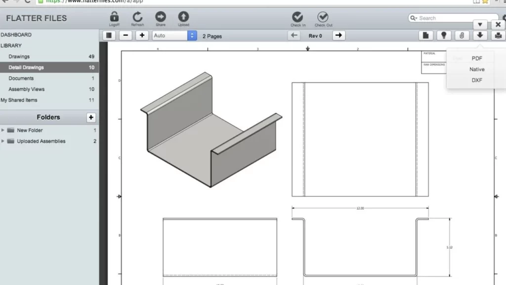
Originally introduced by Autodesk for their AutoCAD software, DXF files are a public standard for CAD data exchange. They contain information about the graphics and the design content and are primarily used for 2D operations.
Features: Human-readable (ASCII) format contains layers, line types, colors, other visual attributes, and extensive third-party support due to its open nature.
2. DWG (DraWinG)
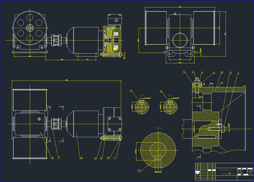
Another product from Autodesk, DWG files, is more feature-rich than DXF. These binary files offer a compact and efficient way to store 2D and 3D designs.
DWG files are more feature-rich than DXF and offer a compact and efficient way to store 2D and 3D designs. They support meshes, solids, surfaces, and more.
However, there are intellectual property concerns due to their proprietary nature, though third-party readers are available. They are generally smaller than DXF files.
3. IGES (Initial Graphics Exchange Specification):
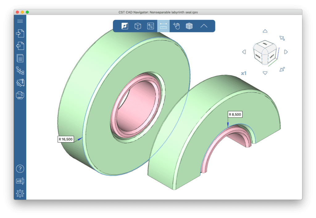
It is recognized as one of the pioneering CAD file formats. IGES is a neutral exchange format that enables compatibility across different CAD software. IGES is a human-readable, ASCII-based format that supports wireframes, circuit diagrams, and solid modelling. It is somewhat outdated but still in use due to its vast compatibility.
4. STEP (Standard for the Exchange of Product Data) Formats – AP203 vs. AP214 vs. AP242:
STEP files are a comprehensive set of formats that aim to cover the entire product life cycle. Among them, AP203, AP214, and AP242 are the most noteworthy, each catering to specific needs.
5. STL (Stereolithography)
A format native to the stereolithography CAD software, STL, is commonly used for computer-aided design and manufacturing.
It represents 3D surface geometry without color or texture. It is widely used for 3D printing, and both ASCII and binary versions are available.
Table: Comparison of AP203, AP214, and AP242 STEP Formats
| Attribute | AP203 | AP214 | AP242 |
|---|---|---|---|
| Primary Focus | Configuration control for design entities. | General structure and automotive. | Aerospace and automotive applications. |
| Data Types | Core data only. | Extensive, including colors. | Most comprehensive – combines AP203 and AP214 with added functionalities. |
| Compatibility | Supported by most CAD software. | Wide range, though less than AP203. | Cutting-edge, suitable for modern applications. |
| Usage | Traditional, for fundamental applications. | More specialized use cases. | Contemporary, for complex scenarios. |
Why do File Formats Matter For Your Business?
Choosing the right CNC file format is more than just a technical decision. It directly impacts the quality of machining, efficiency, and even the cost-effectiveness of a project:
- Precision & Quality: Some formats are more suitable for intricate designs, ensuring that every detail is captured and reproduced.
- Compatibility: Not every CNC machine reads every file format. Choosing a universally accepted format minimizes compatibility issues.
- Data Integrity: Some formats are more robust than others, reducing the risk of data corruption or loss during transfers.
As CNC technology evolves, so will the file formats that drive them. Staying abreast of these formats ensures that manufacturers and designers can leverage the latest advancements in CNC machining to their fullest potential.
The Connection of CAD & CNC
The manufacturing world has witnessed an era-defining convergence over the last few decades. At the heart of this transformation lies the unison of CAD (Computer-Aided Design) and CNC (Computer Numerical Control) technology.
This alliance has forever changed the design, prototyping, and production landscape in global industries.
Let’s delve deep into understanding how CAD and CNC harmoniously work together to produce unprecedented accuracy, efficiency, and innovation in modern manufacturing.
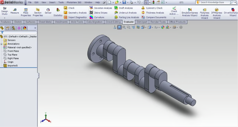
Understanding CAD: The Digital Design Maestro
CAD software is akin to an architect’s digital drafting board, providing tools to create intricate 3D models and 2D vector-based drawings of physical components.
CAD software offers high precision in designs by allowing exact measurements down to micrometers. It lets users view designs from multiple angles, simulate real-world stresses, and visualize internal structures without physical prototypes. Modifying designs is also easy, with changes propagating automatically across linked components or assemblies.
Once a design is set in CAD, it’s time for CNC to shine. CNC machinery reads the digital design files and translates them into physical parts, carved, milled, or sculpted with breathtaking accuracy.
CNC machines operate autonomously once programmed, reducing human error and increasing consistency. They are capable of handling a variety of materials, from wood and plastics to metals and ceramics. CNC machining is adaptable to various production needs, whether a one-off prototype or mass production.
The Seamless Workflow from CAD to CNC
- Design Phase: Engineers and designers use CAD software to create a digital model of the component or product, ensuring all measurements, tolerances, and specifications are accurate.
- Conversion to CNC-Readable Format: The CAD design is translated into a CNC-compatible file format, often using CAM (Computer-Aided Manufacturing) software. This process generates the G-code, the language CNC machines understand.
- Machine Setup: The appropriate material is loaded into the CNC machine, tools are calibrated, and the machine is set up based on specifications from the CAM software.
- Production: The CNC machine reads the G-code and starts creating the physical part, milling, drilling, turning, or shaping the material based on the design’s directives.
- Quality Check: After machining, the component undergoes quality checks to match the CAD design’s specifications.
Table: Efficiency Gains with CAD & CNC Integration
| Traditional Manufacturing Steps | CAD & CNC Integrated Steps | Time Saved |
|---|---|---|
| Manual Drafting | Digital CAD Design | 40% |
| Physical Prototyping | CAD Simulation & Testing | 60% |
| Manual Machine Setup | Automated CNC Setup | 50% |
| Manual Machining | Automated CNC Machining | 70% |
| Manual Quality Checks | Digital & Automated Checks | 30% |
Integrating CAD and CNC speeds up production and ensures precision while saving costs. CAD’s digital simulations eliminate the need for multiple physical prototypes, while automated CNC machining accelerates production. The precision of digital designs is carried through to production, reducing wastage and ensuring products meet strict tolerances. Although initial setup costs can be high, CAD & CNC’s speed and accuracy reduce long-term costs, making production more efficient and cost-effective.
Unveiling CNC Design Files
In CNC machining, the design file acts as a bridge between the concept and the tangible product. While the machinery and tools play a vital role, without the right design file, they are akin to a ship without its navigator. Let’s pull back the curtain and discover what these CNC design files are and why they’re indispensable.
1. The DNA of a CNC Design File
A CNC design file is a digitized representation of the design meant to be executed on a CNC machine. These files guide the machine on how to move, carve, drill, or mill, bringing a design to life.
A CNC design file encompasses paths, coordinates, and tool information. Paths represent the tool’s trajectory on the material, directing it on where to move and at what depth. Coordinates use the X, Y, and Z axes to pinpoint the exact locations for machine operations. Tool information includes details about which tool to use, its size, rotations per minute (RPM), and feed rate. These components guide the machine on how to move, carve, drill, or mill, bringing a design to life.
2. CNC Design File Formats & Their Significance
Many file formats are available, each with unique features and suited for specific tasks.
Common CNC Design File Formats include DXF (Drawing Exchange Format), DWG, G-code, IGES, and STEP.
Table: Most Popular CNC Design File Formats and Their Applications
| File Format | Description | Common Uses |
|---|---|---|
| DXF | 2D drawing format | Laser cutting, plasma cutting |
| DWG | Native to AutoCAD | Detailed designs, architectural plans |
| IGES | 3D model data exchange | Data sharing between CAD programs |
| STEP | 3D data exchange with more detail than IGES | Complex 3D modeling |
| G-code | Direct machine instructions | All CNC machining processes |
The Implications of File Format in CAD
When choosing a CAD file format, it’s important to consider interoperability, file size, and data fidelity. Not all CAD programs read all file formats, so picking a widely accepted format ensures smooth transitions between different software.
Some formats are more compact than others, which can be crucial when working with intricate designs or sharing files online. Additionally, some formats might not retain all the data, especially when transferring files between different CAD software.
CAD File Formats: More than Just Extensions
For those who are uninitiated, choosing a file format in CAD software is like choosing between .doc and .docx while saving a Word document. But the reality is far more nuanced. The choice of file format can dramatically impact the ease of collaboration, compatibility across software, and even the fidelity of the design. A wide array of file formats are tailored to specific needs.
Here’s a glimpse into some of them:
STEP vs. IGES: The 3D Modeling Heavyweights
- STEP (Standard for the Exchange of Product Data): With its variants like AP203 and AP214, STEP is designed for complete data exchange, encompassing geometry, topology, and colour.
- IGES (Initial Graphics Exchange Specification): Older than STEP, IGES is universal but might lack some of STEP’s comprehensive features.
Table: Key CAD File Formats and Their Specificities
| File Format | Description | Best Suited For |
|---|---|---|
| STEP | Comprehensive 3D data | Detailed 3D modeling |
| IGES | Universal 3D data | Basic 3D designs and transfers |
| DXF/DWG | 2D design data, with DWG being native to AutoCAD | Architectural designs, floor plans |
| STL | 3D model data, widely used for 3D printing | 3D printing tasks |
| OBJ | 3D geometry without CAD-specific features | Rendering and animation |
On AP203, AP214, and AP242: The Variants of STEP
A mention of STEP formats wouldn’t be complete without discussing its most popular extensions:
- AP203: Defines the geometry, topology, and configuration management data.
- AP214: Includes everything in AP203 plus colors, design intent, and electrics.
- AP242: Aims to merge the features of AP203 and AP214, offering a more holistic approach.
If you want to explore the CNC Machining Process, Benefits & Manufacturing Methods more in-depth. Then here is a complete guide made by our expert for you:
Elevating CNC Precision with Prolean’s Services
In Computer Numerical Control (CNC) machining, precision, efficiency, and reliability aren’t just buzzwords – imperatives. ProleanTech’s CNC machining services have consistently set benchmarks in these areas, offering unparalleled quality and precision.
Let’s delve deeper into how Prolean stands out and what it brings to the CNC table.
Commitment to Precision
ProleanTech isn’t just another CNC service provider. Its unwavering commitment to precision makes it a trusted name among industries where even a micrometer’s deviation can make all the difference.
Our precision-driven approach comprises cutting-edge machinery, highly trained technicians, and stringent quality control. They use state-of-the-art CNC machinery to ensure every cut, drill, or mill is executed impeccably. The seasoned experts on their team bring years of experience and a commitment to precision.
Customized Solutions for Every Need
ProleanTech understands that every project is unique and demands a bespoke approach.
We provide prototyping services to ensure the final product aligns with the envisioned design. With their advanced CNC machines, we can handle bulk orders without compromising quality or timelines. Our team can translate complex designs into tangible products, thanks to their advanced software capabilities that can interpret many CNC files and formats.
Staying Ahead with Technological Advancements
In the ever-evolving world of CNC machining, resting on laurels is not an option. Prolean invests heavily in keeping its technology and skills updated. We update software regularly to ensure compatibility with the latest CNC file formats and continuous training for our workforce to keep up with the latest CNC techniques and best practices.
This allows us to provide our clients with precision and efficient CNC services.
Our Edge in CNC Machining
What truly sets Prolean apart is its technology or expertise and a combination of several factors. We offer a range of CNC services, such as milling, turning, and routing, with a commitment to precision, customized solutions, and staying ahead of technological advancements.
We provide quick turnaround times, competitive pricing, and dedicated customer support from understanding client requirements to after-sales support. Contact our experts now!
Conclusion
Navigating the intricate pathways of CNC machining is a demanding task, demanding precision, expertise, and a profound understanding of the intricate dance between software and machinery.
CNC files act as the blueprint, guiding machinery to sculpt, mould, and create with impeccable accuracy. As industries increasingly lean on technology to produce intricate designs and high-quality products, the role of precise file formats and their compatibility with CAD systems becomes paramount.
ProleanTech CNC services and our commitment to precision and excellence stand as a testament to how technology can craft marvels when wielded with expertise. As we progress into the technological age, partnerships like these – between machine and man, software and hardware, design and execution –will steer the ship of innovation.
FAQs
What are CNC files?
CNC files are digital blueprints machines used to carve, cut, or mould material. They contain specific instructions that guide the machine in producing a particular design.
What Files Does a CNC Read?
CNC machines primarily read G-code files (NC, TAP, CNC, or TXT), generated from CAD/CAM software. Common input formats include DXF, DWG, STEP, IGES, and STL, which are converted into machine-ready instructions.
Can I Use an STL File for CNC?
STL files are designed for 3D printing, not CNC machining. However, they can be converted into STEP or IGES for CNC use, though complex geometries may require additional optimization.
What File Is Used for CNC Cutting?
DXF and DWG files are standard for laser, plasma, and waterjet cutting as they contain vector-based 2D designs. For 3D CNC milling, STEP, IGES, and G-code files are commonly used.
What Is a DXF File for CNC?
A DXF (Drawing Exchange Format) file is a 2D CAD format used in CNC for cutting, engraving, and routing operations, ensuring high precision and compatibility across different machines.
Why is the file format important in CNC machining?
The file format determines the compatibility with different CNC machines and software. Using the right format ensures precise execution of the design without errors.
How does CAD software relate to CNC?
CAD (Computer-Aided Design) software is used to create the design or model of the product. This design is then converted into a CNC file, which the machine reads to produce the physical product.
What is the difference between STEP AP203, AP214, and AP242?
These are all standardized CAD file formats. While they have many similarities, they differ in the features and data they support. AP242, for instance, is the most recent and integrates the best of both AP203 and AP214.
How do ProleanTech CNC services stand out?
ProleanTech is renowned for its precision, state-of-the-art technology, and skilled technicians. They offer customized solutions, ensuring each project, big or small, receives individual attention and excellence.
0 Comments