Ever since the dawn of computer numerical control (CNC) technology, the manufacturing industry has seen a tremendous surge in productivity and precision. At the heart of this machinery are intricate 3D drawings or models, which serve as the blueprint for creating complex and accurate parts. The ability to interpret these 3D drawings is an invaluable skill for professionals involved in CNC machining. This article is a comprehensive guide designed to help readers understand and effectively interpret 3D drawings for CNC machining.
Related Resource: 2D vs 3D Drawings in Manufacturing: A Comprehensive Comparison
Why are 3D Drawings Crucial in CNC Machining?
3D drawings or models play an indispensable role in CNC machining for several reasons. Let’s elaborate on some of them in brief.
1. More Detailed and Accurate Representation
3D models offer a more detailed and accurate depiction of a part or component compared to 2D drawings. While 2D drawings are limited to two dimensions, 3D drawings capture all three dimensions, providing a complete representation of the object. This ensures that complex geometries and details can be clearly defined and understood, reducing the risk of errors during the manufacturing process.
2. Better Compatibility with Modern CNC Machining
Modern CNC machines are designed to work with digital 3D models. They can interpret the intricate details of a 3D model and accurately replicate them in the final part or component. This compatibility between 3D models and CNC machines significantly streamlines the manufacturing process, ensuring efficiency and productivity.
3. Streamlined Manufacturing Process
With 3D models, multiple perspectives of the object can be examined simultaneously, eliminating the need to cross-reference various 2D drawings. This facilitates a more streamlined and coherent understanding of the product, ensuring a smoother manufacturing process.
Interpretation of 3D Drawings in CNC Machining
Interpreting 3D drawings in CNC machining requires a comprehensive understanding of certain critical elements that define the details and dimensions of a product. Here’s a look at some of these elements:
1. Geometric Dimensioning and Tolerancing (GD&T)
Geometric Dimensioning and Tolerancing (GD&T) is a symbolic language used on engineering drawings and computer-generated models. It communicates the permissible limits of form, orientation, location, profile, and runout of a feature within an exact dimension. Interpretation of GD&T is critical as it determines how parts fit together and function.
2. Surface Finish Symbols
The surface finish symbol indicates the surface texture required on a machined part. It is represented using a checkered symbol. The surface finish requirement can greatly impact the machining process as it might necessitate additional machining, polishing, or finishing processes to achieve the desired texture.
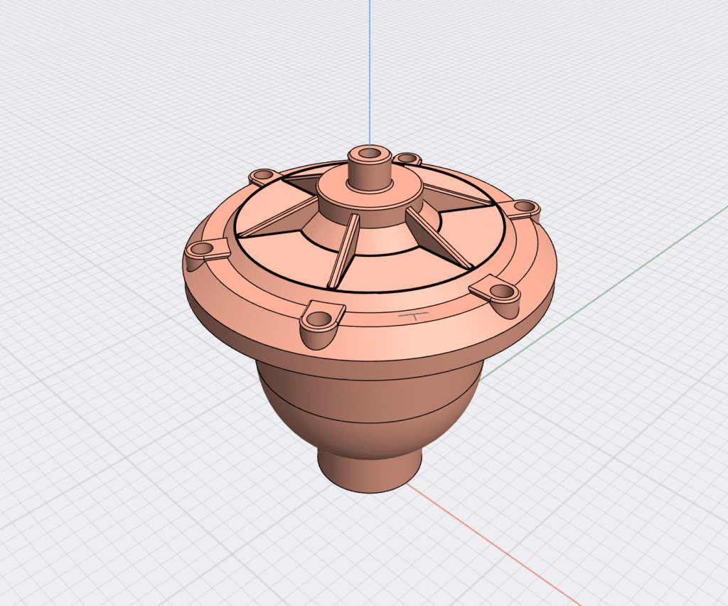
3. Interpreting Views and Perspectives
3D models are often depicted from various views and perspectives, including front, top, side views, and sometimes isometric or perspective views. Understanding these perspectives is crucial for determining the exact dimensions and features of the part.
4. Material Specifications
3D models often contain specifications about the type of material to be used in the manufacturing process. It’s essential to interpret these specifications accurately as they directly affect the part’s properties and performance.
Table 2: Key Elements of 3D Drawings in CNC Machining
| Element | Description |
|---|---|
| Geometric Dimensioning and Tolerancing (GD&T) | Symbolic language is used to specify the permissible limits of form, orientation, location, profile, and runout. |
| Surface Finish Symbols | Symbols indicating the required surface texture on a machined part. |
| Views and Perspectives | Various views and perspectives are used to depict the exact dimensions and features of the part. |
| Material Specifications | Specifications about the type of material to be used in the manufacturing process. |
These are the basic elements involved in interpreting 3D drawings for CNC machining. Proper interpretation ensures that the parts or components are manufactured according to exact specifications, resulting in high-quality products.
Try Prolean Now!
Tips for Interpreting 3D Drawings in CNC Machining
The process of interpreting 3D drawings for CNC machining can be complex and detailed, but with the right knowledge and skills, it can become a straightforward task. Following these tips can enhance your interpretation skills, improve the efficiency of your manufacturing process, and ultimately lead to better product quality. However, once you grasp the basics of interpreting 3D drawings in CNC machining, the following tips can further refine your understanding and improve your interpretation skills:
1. Familiarize Yourself with Standard Symbols and Notations
Familiarize yourself with the standard symbols and notations used in 3D drawings, such as those for dimensions, tolerances, surface finishes, and materials. This will allow you to quickly and accurately interpret the specifications on the drawing.
2. Use Appropriate Software
Utilize CAD (Computer-Aided Design) software that allows you to interact with the 3D model. This can help you to gain different perspectives, measure dimensions directly, and even simulate the drawing for manufacturing process.
3. Collaborate and Communicate
Don’t hesitate to collaborate and communicate with the design engineers when interpreting complex 3D drawings. They can provide valuable insights and clarify any ambiguities in the drawing.
4. Continuous Learning
Stay updated with the latest standards, tools, and techniques used in 3D drawing interpretation. This can significantly improve your accuracy and efficiency.
Prolean’s CNC Machining Services and 3D Drawings
Prolean’s CNC machining services are characterized by precision, efficiency, and quality. And much of these qualities can be attributed to our meticulous approach to interpreting 3D drawings. Understanding the design in 3D format allows our team to visualize and plan the entire machining process even before it starts.
Table 4: Prolean’s CNC Machining Services and 3D Drawings
| Attribute | Role of 3D Drawings |
|---|---|
| Precision | 3D drawings allow precise interpretation of dimensions, tolerances, and geometries. |
| Process Streamlining | With a clear understanding of the 3D design, machining operations can be optimally planned. |
| Quality Assurance | 3D drawings allow accurate verification of the final product against the original design. |
Conclusion
Understanding and interpreting 3D drawings are critical to the success of CNC machining operations. From ensuring the accuracy of dimensions to planning the machining operations, 3D drawings play an instrumental role in the entire manufacturing process. While it may take time and effort to master the interpretation of these drawings, the resultant improvement in efficiency, reduction in errors, and enhancement of product quality make it a worthwhile investment.
FAQs
What are 3D drawings in CNC machining?
3D drawings in CNC machining are digital designs that provide a three-dimensional representation of the part to be manufactured. They are often created using CAD software and provide comprehensive details about the part’s dimensions, geometries, tolerances, and material specifications.
Why are 3D drawings crucial in CNC machining?
3D drawings are critical in CNC machining because they provide a comprehensive representation of the part to be manufactured. They aid in accurate interpretation of dimensions, geometries, and tolerances, which in turn ensure precision in manufacturing.
What are some tips for interpreting 3D drawings in CNC machining?
Some tips include familiarizing yourself with standard symbols and notations, using appropriate CAD software, collaborating and communicating with design engineers, and continuous learning to stay updated with the latest standards, tools, and techniques.
How does Prolean’s CNC machining services utilize 3D drawings?
Our CNC machining services use 3D drawings to ensure precision in manufacturing, streamline the machining process, and assure quality. Our team uses advanced CAD tools to interpret the drawings and verify the final product against the original design.
0 Comments