Injection molding design guide
Injection molding is an efficient method of producing large volumes with consistency and lower per-part cost. It involves injecting the molten polymer into mold cavity and solidifying it into the desired shape.
Although molding technology has many advantages, a DFM-compliant drawing is essential for the processing. Part design directly influences the manufacturability of the mold, the complexity of mold construction, the project budget, the lead time, and surface defects.
This injection molding design guide will elaborate on 12 best practices for DFM optimization, including thickness, ribs, bosses, draft angle, sharp corners, parting line, ejector pins, and injection molding gate.
Let’s get started!
1. Material Selection for Injection Molding Parts
| Material Type | Key Properties |
| ABS | Toughness, impact-resistance, and good finish |
| Polypropylene (PP) | Cost-effective, chemical-resistant, and fatigue life |
| Polyethylene (PE) | Lightweight, flexibility, and moisture resistance |
| Polystyrene | Rigidity, easy to mold, and cost-effective |
| Polycarbonate (PC) | Optical transparency, heat-resistance |
| Polyamide (Nylon) | Low-friction, strength, wear-resistance |
| Polyoxymethylene (Acetal) | Stiffness, low-friction |
| Polymethyl Methacrylate (Acrylic) | High visibility, glossy finish |
| Thermoplastic Elastomer (TPE) | Soft, flexible, and rubber-like material |
| Thermoplastic Polyurethane (TPU) | Toughness, elasticity, and wear-resistance |
| Polybutylene Terephthalate (PBT) | High strength, heat resistance, and electrical insulation |
| Polyethylene Terephthalate (PET) | Good strength, chemical resistance, and dimensional stability |
| Polyphenylene Sulfide (PPS) | Temperature resistance, chemical resistance, and stiffness |
| Liquid Crystal Polymer (LCP) | Dimensional stability, high heat resistance, and low warpage |
A variety of thermoplastic polymers can be processed by injection molding. It is essential to choose the material before the detailed design of the part.
Therefore, identify the application requirements, such as strength, stiffness, corrosion resistance, environmental conditions, etc., and choose the material accordingly.
Although there are 100+ material options, let’s look at a few of the most commonly used polymers in the table below.
Try Prolean Now!
2. Wall Thickness of Molding Part
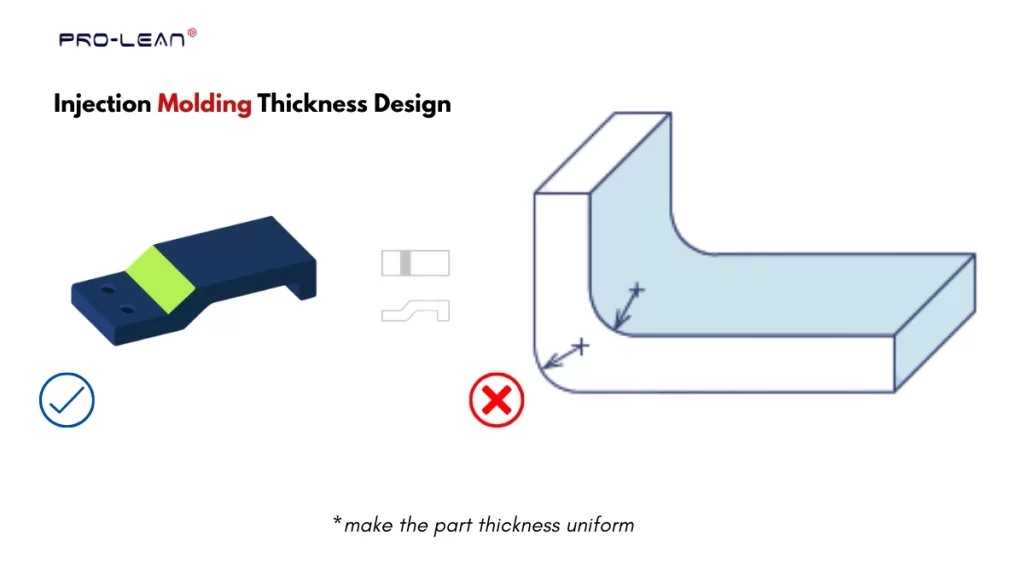
Injection molding thickness
Thickness is a fundamental design parameter for injection molded parts. It defines strength, stiffness, and other properties. Additionally, improper part thickness leads to wrapage and uneven cooling.
Nominal Wall Thickness
Nominal thickness, typically denoted by “t,” refers to the “ thickness value” set for the molding part in the design, which is uniform throughout the geometry. For instance, a nominal thickness of 3 mm means the part is uniformly thicker with value t=3.
Material Type and Thickness Value
The range of minimum to maximum thickness differs from one material type to another. This is because each thermoplastic has different levels of flowability, viscosity, and other characteristics.
You can design thicker parts from materials such as PPSU, PBT, and PEEK. On the other hand, the allowable thickness is lower for materials like ABS, PMMA, and PC.
The table below outlines the recommended injection molding thickness range for various polymers.
| Material | Wall Thickness Range (~ mm) | Wall Thickness Range (~ inch) |
| ABS | 1.14 – 3.56 | 0.045 – 0.140 |
| Polypropylene (PP) | 0.64 – 3.81 | 0.025 – 0.150 |
| Polyethylene (PE) | 0.76 – 5.08 | 0.030 – 0.200 |
| Polystyrene (PS) | 0.89 – 3.81 | 0.035 – 0.150 |
| Polycarbonate (PC) | 1.02 – 3.81 | 0.040 – 0.150 |
| Polyamide (Nylon, PA) | 0.76 – 2.92 | 0.030 – 0.115 |
| Polyoxymethylene (Acetal, POM) | 0.76 – 3.05 | 0.030 – 0.120 |
| Polymethyl Methacrylate (Acrylic, PMMA) | 0.64 – 3.81 | 0.025 – 0.150 |
| Thermoplastic Elastomer (TPE) | 0.64 – 3.18 | 0.025 – 0.125 |
| Thermoplastic Polyurethane (TPU) | 0.64 – 3.18 | 0.025 – 0.125 |
| Polybutylene Terephthalate (PBT) | 2.03 – 6.35 | 0.080 – 0.250 |
| Polyethylene Terephthalate (PET) | 0.64 – 3.81 | 0.025 – 0.150 |
| Polyphenylene Sulfide (PPS) | 0.51 – 4.57 | 0.020 – 0.180 |
| Liquid Crystal Polymer (LCP) | 0.76 – 3.05 | 0.030 – 0.120 |
3. Thickness Uniformity and Transition
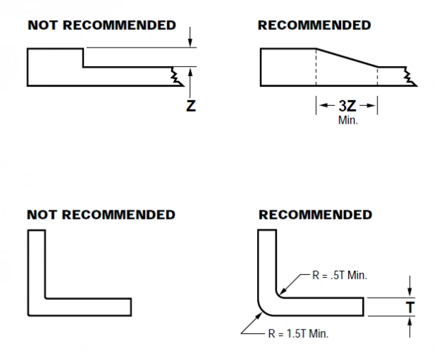
Thickness transition of molding parts
Another injection molding part design guideline is about the uniform thickness of the part throughout the geometry. It is important for efficient filling, cooling, and defect prevention. If injection molded parts require sections with varied thickness, in such cases, use appropriate transitions.
Blend the transitional sections where varied thicknesses meet for better stress distribution and structural integrity of injection molded parts. Additionally, you can also use features like fillets & chamfers.
4. Round Corners with Correct Radii
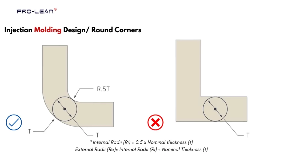
Round corner design
Sharp corners can be problematic in maintaining the high structural strength and ease of mold fabrication. If the corners are sharp & pointy, they concentrate the stress and make it difficult to machine a deep cavity in the mold for them. Therefore, use round corners.
Internal Radii (Ri) = 0.5 x Nominal thickness (t)
External Radii (Re)= Internal Radii (Ri) + Nominal Thickness (t)
5. Draft Angle
Draft angle is another factor to consider while following the injection molding design guide. It is a small, tapered angle on the vertical wall of the part you are designing.
Adding a draft angle is crucial for easy ejection, shorter cooling time, and damage prevention.
Let’s look at the draft angle rules for two different injection molding surface finishing: smooth and textured.
| Condition / Requirement | Draft Angle |
| Smooth finish | 1–2° |
| Textured finish | 2–5° or 1–2° per 0.025 mm texture depth |
Furthermore, you must consider the type of polymer, part geometry, mold construction, and mold finish while choosing the draft angle.
6. Adding Ribs
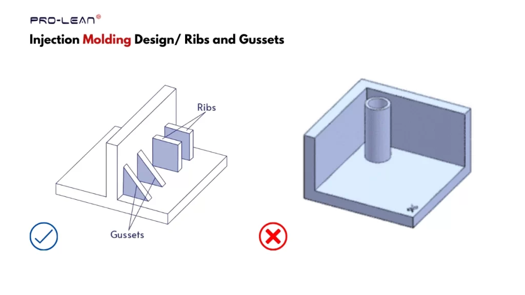
Injection molding ribs design
Ribs are structural reinforcement features on injection molding parts, which are the thin & vertical sections extended from the part surface. You must size the ribs correctly, as well as consider the fillet on the rib’s bottom.
Let’s look at the injection molding best practices for rib design in the table below.
| Rib Design Variable | Guideline |
| Rib Thickness | 0.4–0.6 x wall thickness (t) |
| Rib Height | ≤ 2.5 × wall thickness (t) |
| Draft Angle | ≥ 0.5–1° per side |
| Fillet Radius | 0.25–0.4 x Wall thickness (t) |
| Min. Rib Spacing | ≥ 2× wall thickness(t) |
Try Prolean Now!
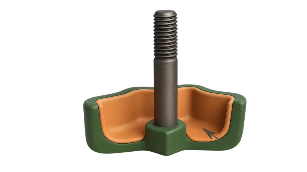
7. Bosses
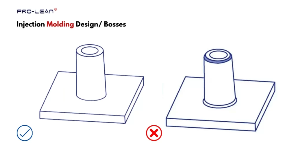
Bosses features
Bosses are critical features in injection-molded parts for receiving the alignment inserts, pins, and fasteners. They are characterized by vertically raised features, typically circular or tubular in geometry.
You must carefully choose the locations of bosses with suitable diameters and thicknesses.
Next, the table below outlines design rules for bosses.
| Boss Design Variable | Guideline |
| Boss thickness (outer wall) | 0.4 to 0.6 x wall thickness (t) |
| Hole | Choose based on the size of the insert |
| Boss height | ≤ 2–3× outer diameter |
| Base fillet radius | 0.25–0.5× wall thickness (t) |
| Spacing from side walls | ≥ 2× wall thickness (t) |
| Support | Incorporate ribs, gussets, etc. |
8. Part Tolerancing
Correct tolerances are especially critical for injection molding assembly of mating parts, i.e., where parts will be further fitted with others to form a final component or product. Otherwise, it causes dimension inaccuracies, poor fits, and misalignment. Meanwhile, over-tolerancing the part increases mold production cost and time.
So, set the following tolerances in your injection molding part design.
- Dimensional ( Thickness, length, height, etc.)
- Flatness and Parallelism
- Concentricity
- Fit tolerance (Clearance & interference)
- Shrinkage tolerance
- Hole Size, if any included.
9. Parting Line
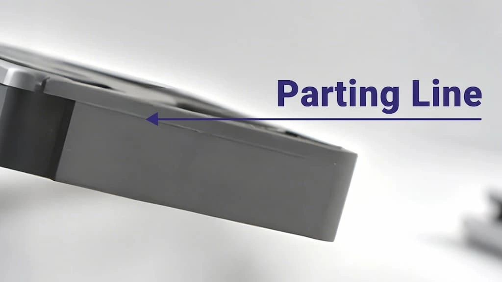
Parting line
The parting line facilitates mold opening, typically located at the center of the mold bottom, though not necessarily. A correct parting line is critical for easy mold opening, reducing the mold construction complexity, avoiding the risk of flashes, and reducing molding cost.
Three key injection molding design guidelines for parting line are;
- Keep the parting line on edges or sharp corners
- Make them as straight and flat as possible
- Do not position them along the stress-concentrated section of the part
10. Injection Molding Gate
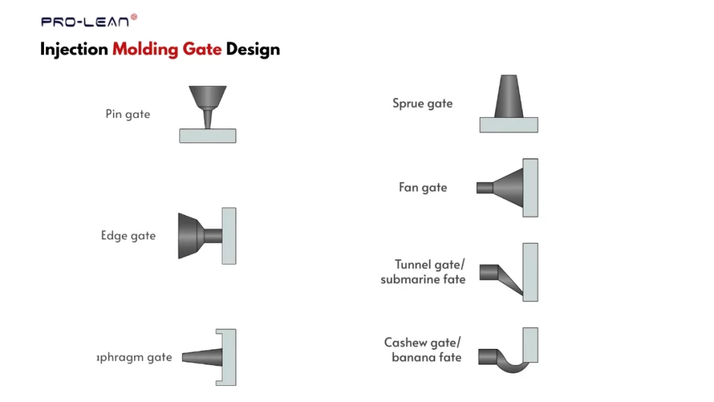
Types of injection molding gates
The type, size, and position of gates are key factors when placing gate openings on the mold. Only one gate is sufficient for a small and simple shape, whereas you might need multiple gates for complex and large-sized injection molded parts.
Designers prefer gates near the parting line, but not always. It is easy to trim the protruding section along the gate after molding.
Next, the table below provides an overview of injection molding best practices for gate type & placement.
| Gate Type | Part Features Suitable For |
| Sprue Gate | Direct gate; best for large, single-cavity molds of thick-walled parts |
| Edge/Side Gate | For parts with flat or slightly contoured profiles |
| Fan Gate | At thin-wall sections of molding parts |
| Tab Gate | Long flat parts that are sensitive to shear loads |
| Pin Point Gate | thin-wall components, multi-cavity molds |
| Cashew Gate | Cosmetic parts with curved or complex features |
| Diaphragm Gate | To maintain a radial flow for cylindrical or hollow shapes. |
| Ring Gate | Circular and tubular parts |
| Film Gate | Very thin-wall and wide flat components |
| Hot Runner Valve Gate | High-quality aesthetic parts |
11. Ejector Pins
Injection molding ejector pins are solid cylindrical pins inside the mold, positioned parallel to the parting line. They are used to remove/eject the part from the mold cavity once the solidification is complete.
Incorrect pin size & installation position lead to part sticking, surface imperfections, and damage.
Here are some critical injection molding part design rules for ejector pins and ejection force;
- Position ejector pins on the thicker, non-cosmetic sections, and avoid them near the sliding tracks.
- Choose the required number of pins to evenly distribute the ejection load.
- A proper clearance is needed, typically 0.02 to 0.05 mm.
12. Overmolding Considerations
Overmolding part
Overmolding is a variation of injection molding that involves molding the multi-material parts by inserting pre-made inserts inside the cavity. Once secondary material is injected, it bonds with the insert and forms a singular item after solidification.
The following are the key factors to consider in overmolding design.
- Material compatibility of the insert and molding plastic
- Interlocks or other mechanisms for adhesion
- Thickness control and supports for multi-shot injection
Try Prolean Now!
Surface Finishing for Injection Molding Parts
Surface finishing is essential for smoothness, custom texture, and aesthetic appeal. While designing the parts, consider the draft angle if you have grip textures.
The table below outlines the common finishes;
| Surface Finish | Description |
| PM-F0 | Non-cosmetic finish |
| PM-F1 | Basic cosmetic finish |
| SPI-A2 | Diamond buffing: high-gloss |
| SPI-A3 | Smooth gloss |
| SPI-B1 | Fine semi-gloss finish |
| SPI-B2 | Medium semi-gloss |
| SPI-C1 | Fine matte surface/stone polishing |
| SPI-C2 | Medium matte |
| SPI-D1 | Light textured finish |
At ProleanTech, we can achieve the finishes mentioned, along with many others. We have the following surface finishing processes;
- Beadblasting
- Polishing
- Chemical etching
- Diamond buffing, etc.
5 Quality Control Systems for Injection Molding
Quality control systems bring consistency in the quality of molding parts and serve as tools to ensure specific industry compliance. Scientific molding, First Article Inspection (FAI), Production Part Approval Process (PPAP), Statistical Process Controls(SPC), and ISO 13485 Qualification are the common systems.
- Scientific Molding: For controlling consistent molding variables across production cycles.
- First Article Inspection (FAI): Initial inspections/measurements for verification of dimensions
- Production Part Approval Process (PPAP): A well-formatted document with verification of compliance with specific industry standards.
- Statistical Process Controls(SPC): Monitoring and detection of variation across molding cycles with statistics.
- ISO 13485: Verifications of each manufacturing step.
How Does Design Impact the Injection Molding Cost?
Injection molding design directly influences the production cost. First, if the design has intricate complex features like undercut & deep cavities, it increases the mold tooling cost. Another factor is cycle time; parts with thicker or uneven thicknesses reduce the production speed.
On the other hand, specialized processes like insert & overmolding reduce the injection molding assembly needs and help to reduce the cost.
Other injection molding design guidelines influencing the cost are tolerances, gate type & placement, and part consolidation.
Upload Your Injection Molding Design for DFM Feedback
Before mold tooling and injection molding production, your design must go through a detailed Design for Manufacturing(DFM) analysis and adjustments for optimization.
A minor DFM error can lead to production defects, malfunctioning, slower cycles, and project failure. Especially, mold toolings are costlier and time-consuming to modify once they are produced.
At ProleanTech, we provide detailed DFM feedback for your injection molding part design. Our engineers will review your design and make suggestions regarding gate location, risk of marks & defects, ejector pins, cavity depth & flowability, and other factors.
So, upload your design to our online platform for injection molding service to get DFM feedback and accurate cost estimation.
Try Prolean Now!
Summing Up
Overall, following the injection molding design guidelines not only ensures the manufacturability, but also boosts the part’s structural integrity, strength, cycle time, production efficiency, cost, and defect minimization. Additionally, the DFM guidelines can differ from one manufacturer to another. So, use the rules/practices provided in this article and contact your manufacturer for further optimization.

0 Comments