
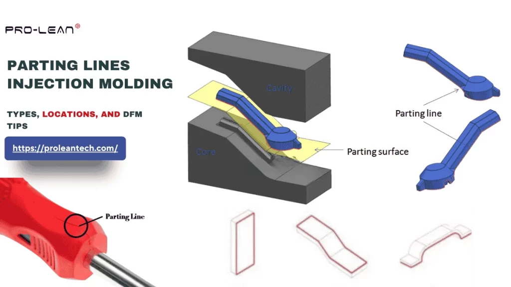
Parting lines injection molding
A parting line is the line in injection molding where two mold halves meet. It is often seen on the surface of molded plastic parts. This line affects the part’s aesthetics and even its functionality. Parting line injection molding aims to manage this inevitable seam.
If the parting line is positioned incorrectly, it leads to plastic leaking (flashing) during the process and forms a visible defect.
If you are facing challenges in mold design regarding where and how to fix the parting line during injection molding design and making DFM strategies, this article will guide you from basic mold tooling to design rules and best practices.
Let’s get started.
What is the Parting Line in Injection Molding?
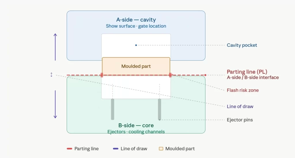
Parting line concept in molding
A parting line is a geometrical feature that is unavoidable in injection molding. It can be identified by visual inspection of molded items; you can notice a seam left on the exterior where the two mold halves (core and cavity) meet during closing and are separated during opening.
A parting line does not damage the part, but it can be a defect if the injection mold is not designed properly and the molding process is carried out with technical errors.
Although the parting line seems a simple feature, it must be designed considering location, suitable parting line type, draft-angle incorporation, and other factors. The ASME Y14.8 standard defines this as a separation line (or surface) between two sections of a mold or die.
Types of Parting Lines in Injection Molding
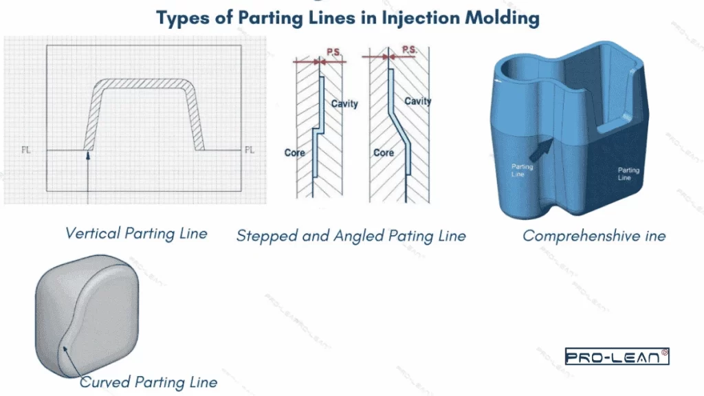
Types of parting lines
There are different types of parting lines, classified based on the geometry and path they follow. It includes vertical, bevel, curved, stepped, and comprehensive parting lines.
Vertical Parting Lines
Vertical parting lines are characterized by their position relative to the mold opening line; it always lies at right angles to the mold opening line. They are the simplest and reduce the mold machining costs.
Best For: Simple part geometries, such as LEGOs, flat lids, enclosure covers, etc.
Bevel Parting Lines
As the name suggests, bevel parting lines include sloping edges to reduce the air entrapments. Instead of a simple vertical shutoff, the edges are beveled at an angle of ~ 3-15 °. These types of parting lines are suitable for intricate molds, such as when opening lies on the extrudes or ribs.
Leave two planes so the beveled line can be machined easily.
Best For: Parts with tapered side walls, draft-angle transitions, etc.
Curved Parting Lines
The line follows a curved path instead of a flat plane. It is not used for parts with simple geometry, as it requires 5-axis (or higher) CNC machines and an advanced EDM system for mold machining. A free-form locus point tracks the geometry, and a parting line is placed across a non-cosmetic surface.
Best For: When the exterior of the parts has a curved surface, or to avoid the line across the visible cosmetic zone.
Stepped Parting Lines
Stepped parting lines are set on different planes at discrete elevations, allowing a line to follow the complex exterior features at different heights.
A heel block or wedge insert is placed on the high-force side of the mold to avoid the risk of mold mismatch, as the step faces higher lateral forces.
Best For: Parts with features/planes at different elevations, such as ribbed panels, and enclosures with interlock features.
Comprehensive Parting Lines
Comprehensive parting lines are not solely distinct from other types, instead it combines two or more types of other parting lines. It includes any combination of vertical, beveled edge, curved, and stepped parting lines, based on the complexity of the desired part.
Best For: Highly complex parts with various geometrical features, where a single type of PL is not efficient, such as medical device housing.
Comparison Table for Types of Parting Lines Injection Molding
| Criteria | Vertical Parting Line | Bevel Parting Line | Curved Parting Line | Stepped Parting Line |
| Mold Complexity | Flat plane and simple mold structure | Moderate complexity, angle shut-off surfaces | High complexity | Moderate–High, and involves multi-plane offsets |
| Mold-Making Cost | Low Cost | Low–Medium | 20–40% higher than vertical lines | Medium to high |
| Machining Method | 2/3-axis CNC milling | 3-axis CNC milling | 5-axis CNC and EDM machining | 3/4-axis CNC machines |
| Flash Risk | Uniform seal area and lowest risk of flashes | Low; bevel reduces air trap and gives a tight seal | Moderate | High at risers |
| Examples | LEGO-style products, bottle caps, enclosure panels |
Tapered plug, connector housing, and conical funnel shell. |
Power tool housing, handle grip, and car door panel | Electronic bezel, stepped lens holder, and multi-level casings |
Parting Line Location
The parting line location must be fixed for manufacturability, as it is directly related to the mold’s core and cavity. Parting line is also related to other mold features, such as draft angle, injection molding gate location, and ejector pins.
- Set the parting line at the largest cross-section of the designed part, so it helps in tooling cost, draft, and DFM.
- Ensure a high part retention on the core side through draft angles; the molded part remains on the core side of the mold after separation.
- If the part geometry allows, always choose the planar parting lines for injection molding processes.
- Place the parting line on a non-cosmetic outer mold line, such as the bottom rim and parting flange.
Can the Location of the Parting Line Influence the Cost of Production?
The location of the parting line influences both mold-making and injection molding costs. Parting lines at difficult-to-machine areas, such as at the intersection of multiple features, increase the mold machining time and cost.
If parting lines are placed in high-pressure sections of the mold, it increases the risk of flash formation and the need for post-processing, thereby increasing production costs. Locating the parting line correctly reduces mold machining costs and streamlines injection molding production.
Try Prolean Now!
Can the Location of the Parting Line Influence the Cost of Production?
The location of the parting line influences both mold-making and injection molding costs. Parting lines at difficult-to-machine areas, such as at the intersection of multiple features, increase the mold machining time and cost.
If parting lines are placed in high-pressure sections of the mold, it increases the risk of flash formation and the need for post-processing, thereby increasing production costs. Locating the parting line correctly reduces mold machining costs and streamlines injection molding production.
Parting Line Design Rules for DFM
Remove Undercuts by Repositioning the PL
The first step in responding to a feature with a side action for DFM is to determine whether relocating the parting line to cross the feature will completely remove the undercut. Often, relocating the PL so that the undercut shape is divided across both mold halves will eliminate or alleviate the situation at no additional tooling expense.
If the PL cannot be relocated for either the direction of draft or due to the aesthetics of the part, then a cam-pin slider/lifter/collapsible core should be used.
Exclude Class-A Surfaces and Functional Interfaces
The PL is an integral part of the molded plastic part and leaves a visible seam mark that remains on the part during molding. DFM dictates that the seam location should be avoided on any Class A cosmetic show surface, bore sealing surface, bearing seat, or precision mating face.
The presence of a PL mark on a functional interface can introduce micro-steps that may interfere with seals or increase friction in running clearances. The seam line must be located on neutral edges, such as flanges, secondary surfaces, or hidden areas of the geometry.
Keep the PL Geometry Planar as Possible
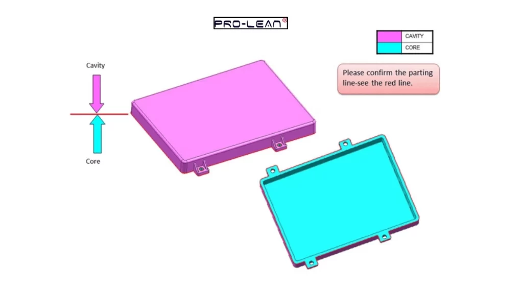
Planer parting line
The (PL) geometry of the mold must be kept as planar as possible so that, when the plastic is injected, the lateral force generated by the plastic entering the cavity will not cause any mold shift of greater than 0.05 mm. By using a flat (vertical) PL, the clamping tonnage will be transmitted uniformly throughout the mold base, enabling 3-axis CNC machining rather than 5-axis machining plus EDM and significantly reducing leader-pin wear.
Maintain a Minimum Draft Angle on all Walls
Draft angle cannot be separated from the placement of the parting line; it must be fixed based on the material type, mold complexity, and desired plastic texture. Consequently, all cavity walls must have a taper from the parting line that is moving away from the draw axis.
- On all polished surfaces: 0.5 °
- standard finishes: 1-2°.
- For textured surfaces: an additional 1.5 degrees of draft for every 0.04 mm of grain depth
Run Mold-Flow Simulation for PL Validation
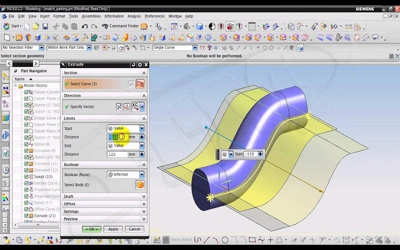
Parting line simulation
Mold-flow simulation (Moldflow, Sigmasoft) can also validate that the selected parting line is not placing any weld lines on load-bearing or cosmetic areas. It helps identify any locations where there will be an air trap located at the perimeter of the parting line.
Try Prolean Now!
Where to Place a Parting Line while Designing a Mold for an Electronic Enclosure?
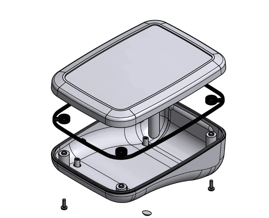
Enclosure injection molding design
Let’s say you are working on an injection-molded enclosures design for an electronic device. The geometry is a simple rectangle, with a two-part assembly (top cover + bottom base). The enclosure dimensions are 200 x 100 x 60 mm, the thickness is 3 mm, the draft angle is 2°, and the desired tolerance is ±0.125 nmm.
Case I: Placing Parting Line on Mid-Plane
If you place the parting line mid-plane or on the perimeter flange between the top and bottom halves, it will avoid complex undercut injection molding and reduce production costs.
Case II: Place along a Non-cosmetic Boundary for Complex Enclosure
If the enclosure needs ribs, bosses, undercuts, slots, and irregular contours, place parting lines along non-cosmetic surfaces, such as the rear side edge and around the stepped flange. You must avoid the display window sections, bottom interfaces, and sealing surfaces.
Flow Lines vs Knit Lines vs Flow Lines Injection Molding
When molten plastic flows through the mold cavity at an inconsistent rate and uneven cooling occurs, streaks or wavy lines appear on the part surface along the flow direction. Meanwhile, knit lines in injection molding refer to thin lines or seams caused by the fusion and cooling of two molten streams before they fully mix.
The parting lines are inevitable and can be adjusted based on desired aesthetics. Flow lines and knit lines can be minimized or eliminated by adjusting the molding process parameters.
- Flow Lines Example: Wavy lines on thin sections of the automotive dashboard
- Knit Lines Example: Streams on the electrical outlet faceplate, between screw holes & outer edges
- Parting Lines Example: Around the outer periphery of the plastic bottle cap
Summing Up
Parting lines injection molding impacts the quality and efficiency of injection molded parts. You can avoid defects like flash, mold mismatch, and aesthetic failure by placing the suitable type of parting line with correct positioning.
At ProleanTech, we provide detailed guidelines and engineering assistance to help you optimize DFM for mold design before the mold machining & molding process. We have a decade of experience producing custom injection molds and molding plastic parts across industries.
Our injection molding service uses automated molding machines capable of producing parts from complex mold designs without defects. Additionally, we are also flexible for rapid tooling and can create intricate molds for plastic parts. For the DFM report & a quote, upload your file on our online platform today.
FAQs
What is the difference between parting line and flash?
A parting line is a visible seam on a part’s exterior where two mold halves meet and separate during the molding process. On the other hand, flash is an aesthetic defect caused by improper parting line design and process handling. It is a thin layer of excess material that escaped through the gaps.
How to find the parting line?
To find the parting line, identify where the two mold halves meet; it appears as a tiny, continuous seam on the part surface. Typically, parting lines can be found in the middle of the plane, at natural edges, in corners, and in non-cosmetic sections.
Does parting line placement affect the cycle time?
Yes, parting line placement affects cycle time, as it plays a significant role in mold opening. cavity filling, and part ejection. A well-designed parting line reduces the cycle time and improves efficiency.
0 Comments