Guide to DFM injection molding
The first step is to design the plastic part. It’s when the design meets the reality of the injection molding that the real challenges begin. Even a seemingly small oversight in wall thickness, gate placement, or other factors can lead to warped parts, expensive mold rework, or production delays, which could push back your launch date by several weeks. Design for Manufacturing (or DFM) is the discipline that bridges this gap, before it becomes an issue.
Injection molding DFM (Design for Manufacturability) is a structured review that determines if a design is really effectively manufacturable. The process examines everything, from the flow of plastic into the cavity of the mold to where to place ejectors to minimize surface distortion. Early identification of these issues is important because plastic molding development costs are high, and tooling represents a significant upfront investment.
ProLean Tech offers injection molding service along with full DFM analysis to its customers as part of their quote process. They can review 3D files to identify potential issues and flag them before tooling. A DFM review can be the most cost-effective option at this point, whether you are looking to refine a design or evaluate injection molding options.
What is DFM in Injection Molding?
Design for manufacturing in injection molding
DFM, or Design for Manufacturing, is a methodology that focuses on creating parts that are simple, efficient, and affordable to manufacture. DFM analysis is used in the context of plastics injection molding to evaluate a 3D model against the constraints of the process. This helps identify potential defects, inefficiencies, or design features that would make tooling unnecessarily complex or costly.
This process is formalized in a DFM report. The report visualizes the findings with annotated 3D pictures, color-coded maps of analysis, and structured suggestions. This gives both designers and mold makers a common reference point before any steel cuts are made.
Why DFM is Important Before Cutting Steel?
The cost of injection mold tooling can be a substantial and largely irreversible expense. Standard production molds can range from a few thousand to tens or even hundreds of thousands of dollars, depending on the complexity, material, and number of cavities. Changing the tooling after it has begun, or even worse, after it is finished, can be expensive and time-consuming.
DFM analysis can identify issues early in the design phase, when modifications are much cheaper than post-tooling corrective actions. DFM injection molding can identify problems early.
- Parts stuck in the mold due to inadequate draft angles
- Sink marks or warping can be caused by uneven wall thickness
- Undercuts that require complex (and costly) side actions
- Placement of gates that results in visible weld marks or surface blemishes
- The rib-to-wall ratios that cause cosmetic defects to the outer surfaces
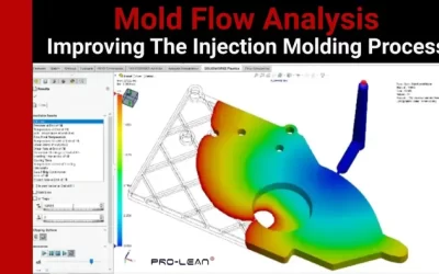
DFM vs. Mold Flow Analysis – What is the Difference?
DFM and Mold Flow Analysis (MFA), although often used together, serve separate purposes. DFM is an evaluation of structural and geometrical features in the part model. Mold flow analysis simulates how plastic melts in the cavity of a mold during filling and packing.
DFM is sufficient for simpler parts. Combining DFM and a full-flow simulation of the mold before tooling is started gives the best picture for complex geometries or high-precision applications.
Try Prolean Now!
The Injection Molding DFM Report: Key elements
Injection Molding DFM Toolkit
A comprehensive DFM report will address the important design and tooling choices that will affect part quality and production efficiency. What every DFM report must include and why it is important.
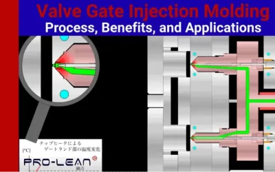
Gate Type and Location
The gate is where molten plastic enters the cavity of the mold. The type and location of the gate have a direct effect on the part’s appearance, structural integrity, and cycle efficiency. The wrong gate position can lead to warping, weld marks, and visible scars on cosmetically sensitive parts.
The three most common types of gates evaluated by DFM are:
Direct / Sprue gate:
It is simple, but it leaves a large and often visible scar. Avoid surfaces that are important in appearance.
Side / Edge Gate:
It is more controllable and can be used for multiple-cavity layouts. It leaves small edge marks, which may be acceptable in certain assembly contexts.
Banana/Submarine Gate:
Consumer parts are the preferred choice. The gate scar is routed to a concealed surface, so that no secondary finishing or trimming is required. Due to the higher flow resistance, it requires a more precise ejection design.
A hot runner system can be used to control runner lengths and waste material for single-cavity moulds with gates on only one side.
Comparing Gate Types
| Gate Type | Best for | Gate Scar Visibility | Recommended For |
| Direct / Spruegate | Simple and low-appearance components | High — visible blush in the center | Appearance parts are not recommended |
| Side/Edge Gate | Simple parts, multi-cavity molds | Small marks at the edges | Useful for applications other than cosmetics |
| Banana / Submarine Gate | Consumer products, assemblies | None — hidden after assembly | Most applications are recommended |
| Hot Runner Gate | Large single-cavity high-volume parts | Minimal — Near-zero Waste | Best for large-scale production |
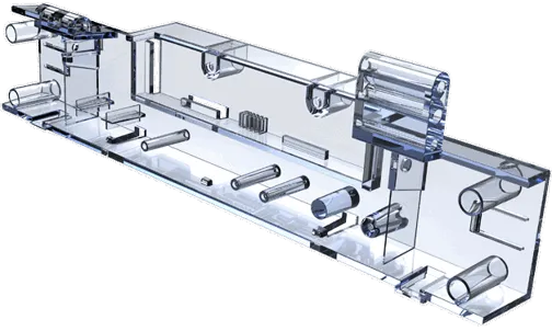
Ejector Pin Placement
After each cycle, ejector pins are used to push the part out of its mold. It is important to place them correctly: too few or incorrectly placed pins will distort the part or cause visible stress marks (whitening) on its surface.
The following are some of the best practices for ejector-pin layout during a DFM evaluation:
Place pins near ribs or bosses where the resistance to demolding is greatest
- Use ejector tubes at boss locations that have through-holes
- Distribute pins symmetrically to balance the ejection force and prevent part tilting
- Make sure that pin marks are placed on surfaces other than cosmetic ones whenever possible
To balance the resistance forces, more ejector pins will be required, the greater the number of ribs.
The Parting Line Position
The parting line is the point where the two halves meet. The part always has a visible mark. DFM aims to place this line in a way that it has minimal visual and functional impact.
Parting lines are placed easily on flat or stepped panels. The orientation of the parting lines in complex geometries or tubular shapes can impact draft angles, dimensional tolerances, and runner length. A DFM should address all options and tradeoffs.
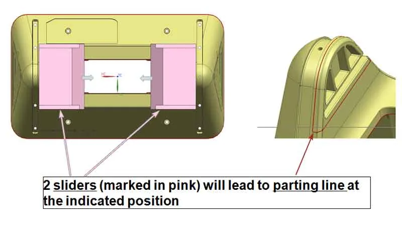
Undercut Lifters and Sliders
Lifters or sliders are required when a part has undercuts, which would prevent it from being removed directly from the mold. They add complexity and cost to the tooling but are necessary for parts with complex geometries.
DFM analyses map the locations of all lifters and sliders required and indicate the line marks that they will leave on the surface of the part. Mold wear at moving interfaces becomes more noticeable over time, which is important for high-volume production.
Wall Thickness and Rib Design
The principle of uniform wall thickness in injection mold design is fundamental, and it’s also one of the principles that are most often violated. If walls are not uniform in thickness, the plastic will fill and cool at different rates. This can cause internal stress and sink marks.
DFM wall thickness analyses checks for:
- Walls are too thick, resulting in sink marks and a longer cycle time
- Walls are too thin (causing structural weaknesses or short shots)
- A sudden transition between thick and thin sections
- Too high a ratio of rib-to-wall-thickness — Ribs should be typically 50-60% the thickness of the adjacent wall to avoid sinkmarks on the opposite side
The DFM report must document any expected consequences, such as the ribs on an angled surface.
Draft Angle Analysis
The draft angles are the small taper added to the vertical walls of the part in order for it to release from the mold cleanly. Parts that lack sufficient draft will stick, drag, or deform when ejected.
Modern CAD programs include draft angle analysis tools that color-code surfaces based on their draft condition. Typically, green is used for surfaces with adequate draft and red for surfaces with zero or negative draft. Gradient colors are also available. This analysis should be included in the DFM report, with specific callouts of any surfaces that require draft modification.
In general, it is recommended that most surfaces be injection-molded with a minimum draft of 1-2°. Textured surfaces need more draft, usually 3-5 degrees, depending on the texture depth.
Try Prolean Now!
Injection Molding Tooling: Key DFM Considerations
Design for manufacturing guide in injection molding
DFM analysis is not isolated; it informs decisions about injection molding tooling. The tooling decisions made during the DFM phase have a long-term impact on part quality, production capability, and total cost ownership.
Selecting Mold Bases for Short Production Runs
Not all products require a hardened mold for production. Aluminum or semi-hardened mold bases are a more cost-effective and faster way to produce first parts for prototyping, bridge manufacturing, or low-volume runs. When recommending materials and standards for mold bases, DFM should take into account the intended production volume.
The following are the key considerations when selecting mold bases for short production runs:
- Aluminum molds are faster to machine and cheaper. They frequently run 20,000–100,000+ cycles depending on alloy, design, and material.
- P20 steel moulds: Excellent balance between machinability, durability, and suitability for medium-volume manufacturing
- H13/hardened steel molds are required for high-volume applications, abrasive material, or tight tolerance applications
- Master Unit Die (MUD) Systems: Replaceable inserts for a standard base mold — Ideal for product families and frequent design iterations
Multi-Cavity Tooling vs. Single-Cavity Tooling
The number of cavities in a mould affects the part cost per cycle. It also impacts the runner system, gate placement, and machine weight requirements. DFM should consider the cavity count when making tooling recommendations.
Multi-cavity moulds can reduce the cost per part, but they increase initial tooling costs and require tighter consistency in dimensions between cavities. Starting with a single cavity tool, or a prototyping insert, allows you to make design changes before scaling up. This is especially useful for new products and designs that have not been proven in production.
Try Prolean Now!
Conclusion
DFM analysis does not just represent a formality. It is a high-return investment in the plastic injection mold process. DFM analysis, by systematically examining gate placement, ejector setup, wall thickness, Draft angles, Parting Lines, and Tooling Strategy before production begins, eliminates the costliest category of problems, those discovered after the tooling has been completed. Combining mold flow simulation with complex applications gives mold designers and mold makers a solid, shared foundation to make decisions.
ProLean Tech provides full DFM analysis with its injection molding services, helping customers to identify and resolve design problems before they commit to tooling. Contact the ProLean Tech team for a DFM quote and review if you are ready to take your design from concept to production, or if you want a second opinion.

0 Comments