Injection molding weld lines
Alt text: Featured article image titled “Injection Molding Weld Lines – Causes, Effects, & Prevention” with a close-up of a gray injection-molded plastic part showing a visible weld line on its surface
Weld lines are some of the most persistent challenges in injection molding. They affect both the structural integrity and visual appeal of the molded part. From our injection molding experience, eliminating these defects results in higher user satisfaction and ultimately, better performance for businesses.
A lot revolves around this phenomenon, including the causes, tips for avoiding the problem, and what a weld line looks like.
With remedies such as parameter control, better mold design, and advanced engineering approaches, no reason that weld lines in plastic injection molding should be a pestering issue. A seasoned injection molding service company can deliver strong, durable, and defect-free parts.
We cover all this information in this comprehensive guide to ensure you insist on quality services and seek a partner that delivers exactly that.
What Is a Weld Line in Injection Molding?
A weld line in injection molding is a visible weak point or line on a part, sometimes informally called a mold line. It is one of the common molding defects. Other defects include flash, warpage, sink marks, short shots, and flow lines in injection molding.
You can also call it a type of seam, often in the knit lines injection molding defect category, that develops at the meeting point of multiple molten plastic flow fronts. It forms when these flow fronts in the mold cavity fail to fully fuse.
The incomplete molecular bonding produces a weak point, which often appears as knit lines injection molding issues. A weld line affects both the aesthetic appeal and mechanical strength of the plastic.
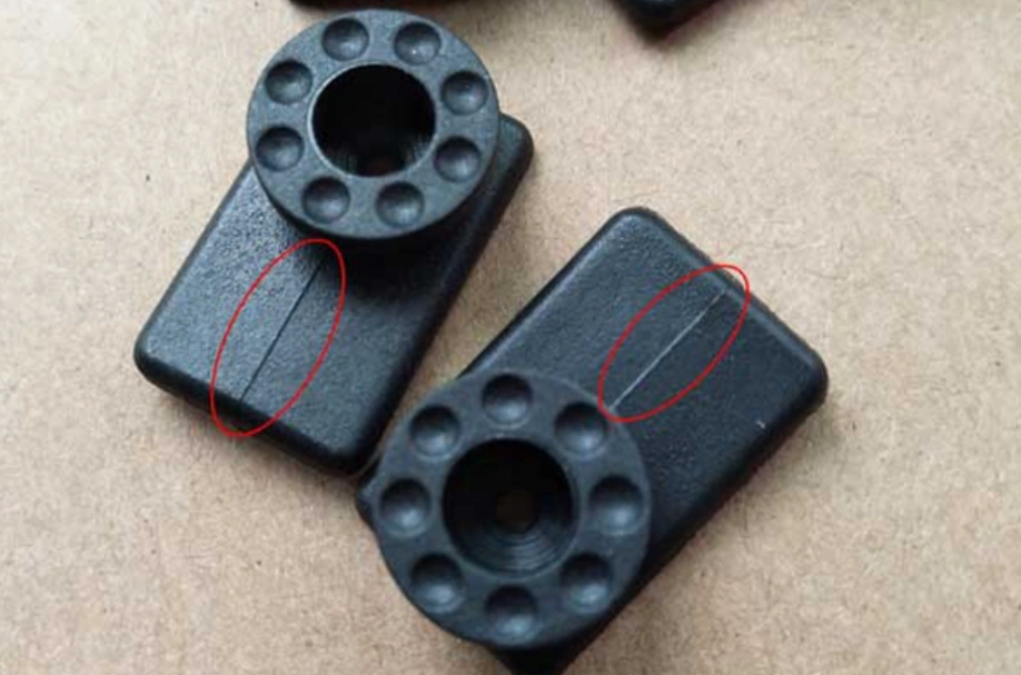
What Does a Weld Line Look Like?
Since a weld line results from flow fronts that move in opposing directions, it presents as a thin, linear discontinuity on the part’s surface, which some people can call a mold line. If the polymer is reinforced, you may find a shift line in the fiber orientation.
For extreme formations, a weld line shows as a depressed or raised line.
Injection molding weld lines
Try Prolean Now!
How Injection Molding Weld Lines Form (Causes of Weld Lines in Injection Molding)
Weld lines can be caused by low injection pressure, low injection speed, low heat, material properties, poor mold design, and the presence of additives.
Low Injection Pressure
Insufficient injection pressure results in low packing force at the merging melt fronts and can enhance air entrapment if venting is inadequate. The knit zone becomes mechanically weak. Unexpected cracking can easily occur at these points.
If an injection-molded part fails around holes, snap-fit features, or ribs, low injection pressure is likely the cause. However, other potential causes include low melt temperature and poor gate location.
Low Injection Speed
If the injection speed is too low, the flow front edges cool prematurely. This is evidenced by seam lines and flow lines in injection molding, both related to inconsistent material flow. For structural parts, this weld line is not just an eyesore; it is a point of reduced tensile strength.
Low Melt Temperature and Low Mold Temperature
Low mold temperature and low melt temperature are undesirable. They promote weld line formation through faster freezing of the flow front and high viscosity, respectively. Since the bonding is incomplete at the interface, parts can suffer from premature failures, especially with poor venting.
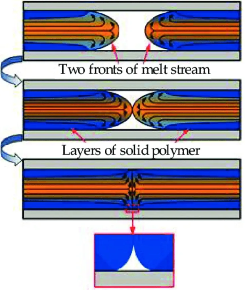
Weld line formation
This is a nightmare for businesses due to the potential for warranty claims and product recalls.
Material Properties
Polymers have different responses to weld line instances. For instance, glass fiber–reinforced plastics tend to form weak weld lines in plastic injection molding. This is an important point to remember when choosing a material for structural integrity.
The following table compares the sensitivity for weld lines in different resins.
| Plastic resin type | Visibility of injection molding weld lines | Strength reduction |
| Amorphous – ABS, PC, PMMA | High | Medium to high |
| Crystalline – PE, PP | Low | Minor |
| GF-Reinforced Grades | High | Extreme |
Poor Mold Design
Manufacturers can influence the formation and placement of injection molding weld lines through design. When design features – gates, wall thickness transitions, inserts, etc. – are poorly placed, these defects can form.
A poor placement of a gate, for instance, can trigger convergence of flow fronts at high-stress points. You can imagine what this structural weakness means for a load-bearing component.
Additives
Additives commonly used in injection molding materials include fillers, flame retardants, and colorants. They can affect flow interfaces, particularly by interfering with the polymer chain mobility.
Some weld lines are more visible due to the presence of these types of additives.
Air Pockets
Air pockets, commonly caused by inadequate venting, are simply trapped air that prevents thorough contact between melt fronts. Proper venting is an effective way to prevent this injection molding defect.
You can also refer to our Injection Molding Defects Chart for a quick comparison of common defect types and causes.
Effects of Injection Molding Weld Lines (Why You Should Avoid Them)
The convergence of melt flows can form weld lines, with the effects being either cosmetic or major. Professional overmolding services avoid weld lines and knit lines injection molding defects to safeguard the aesthetics, strength, and functionality of parts.
Aesthetic Effects
A poorly placed weld line can seriously affect the aesthetics of an injection-molded part. Weld lines are considered injection molding defects and are visually unpleasant, much like flow lines injection molding. That’s because they can detract from the designed appearance. An item that is polished can appear less polished due to these marks.
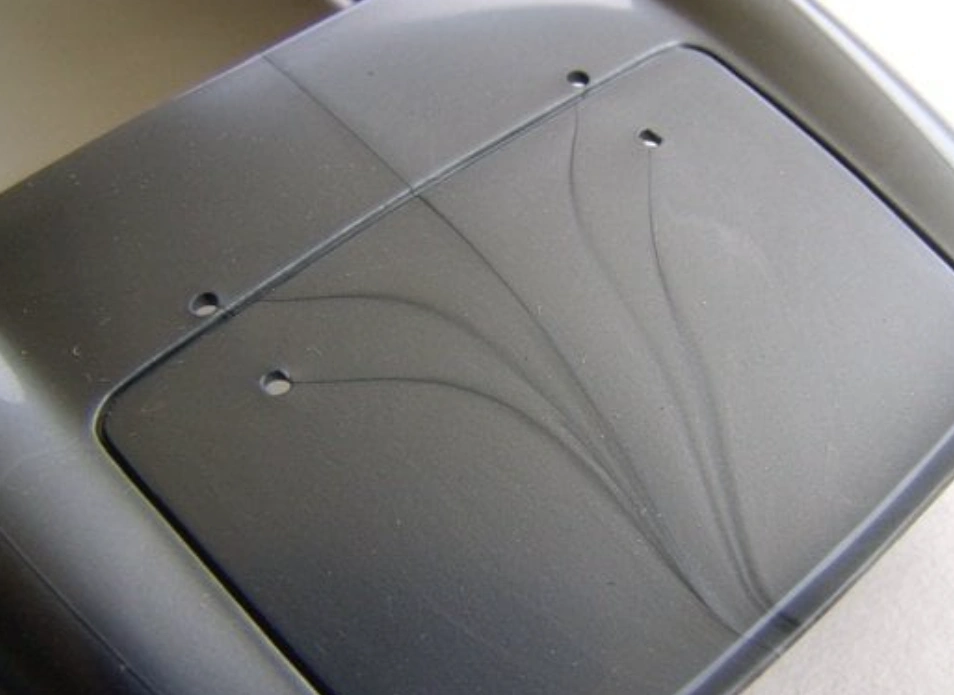
Aesthetic effect
Strength of the Part
A weld line in injection molding is a serious problem because it can reduce the part’s mechanical strength. The points where the plastic melt doesn’t fully bond are weak points.
Functional Issues
The performance of injection-molded parts depends heavily on dimensional accuracy and proper fit. Weld lines affect these elements. In so doing, they reduce the part’s functionality. It means that if, for instance, a part has these defects, you can encounter challenges during assembly.
Try Prolean Now!
Tips to Prevent Weld Lines in Injection Molding
Tips to counter weld lines and their effects on injection molded parts include the use of high-quality parts, application of the recommended pressure, using the correct temperature, and expert mold design.
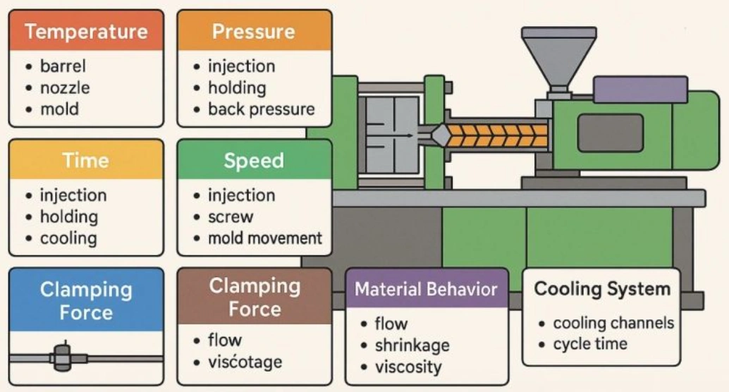
Injection molding process parameters to control
Use High Quality Plastics
High-quality plastics are recommended in injection molding. Such plastics don’t contain additives that may affect the proper flow of the molten material. Therefore, they are less likely to form weld lines.
Apply the Recommended Pressure
Sufficient pressure is required for the seamless merger of flowing molten plastic. The right pressure ensures the plastic flows at the right force and speed. It can help prevent the formation of weld lines.
Maintain the Right Temperature
If the temperature of the molten plastic is lower than recommended, the plastic may solidify before combining effectively with other flows. Therefore, maintaining the design temperature is critical in the prevention of weld lines.
Proper Mold Design
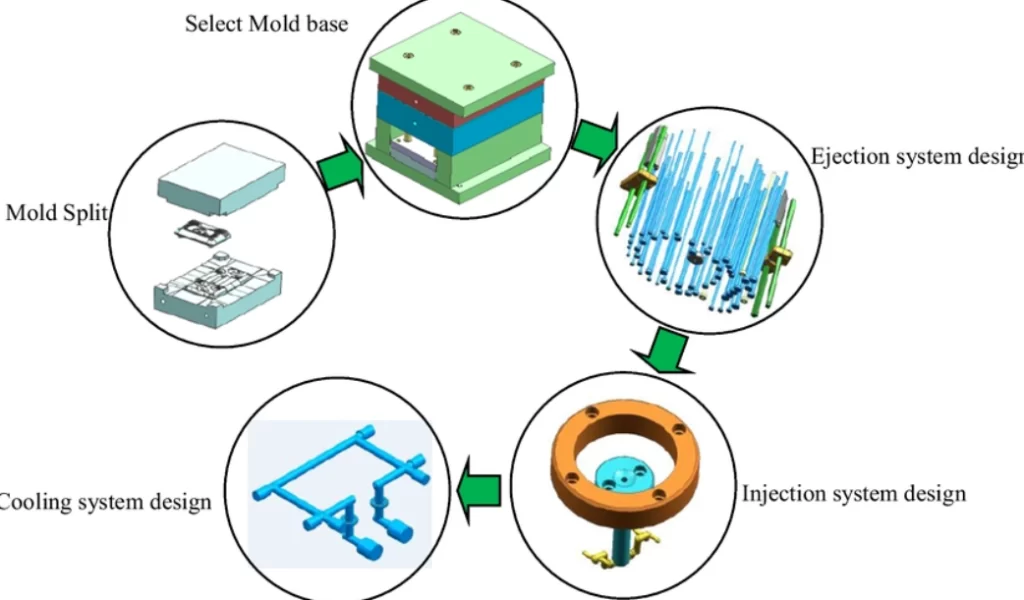
Mold design process
Proper mold flow also depends on the mold design. Overly thick walls are particularly discouraged because they can create inconsistent flow rates and differential cooling rates.
A well-designed mold incorporates elements such as;
- Balanced runner systems
- Enough venting at flow convergence points
- Consistent wall thickness
- Application of modern mold flow analysis (MFA) tools
- Optimized gating – Proper gating is required for enough packing and balanced filling
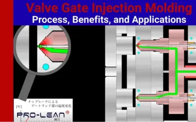
Three Methods to Modify an Injection Mold Design
The most effective methods to modify mold design to minimize weld line in injection molding are cooling system redesign, runner system optimization, and gate design modification.
- Cooling System Redesign – Heat dissipation can be enhanced through cooling channel adjustments. Such redesigns can minimize warpage and shrinkage, and reduce cycle time.
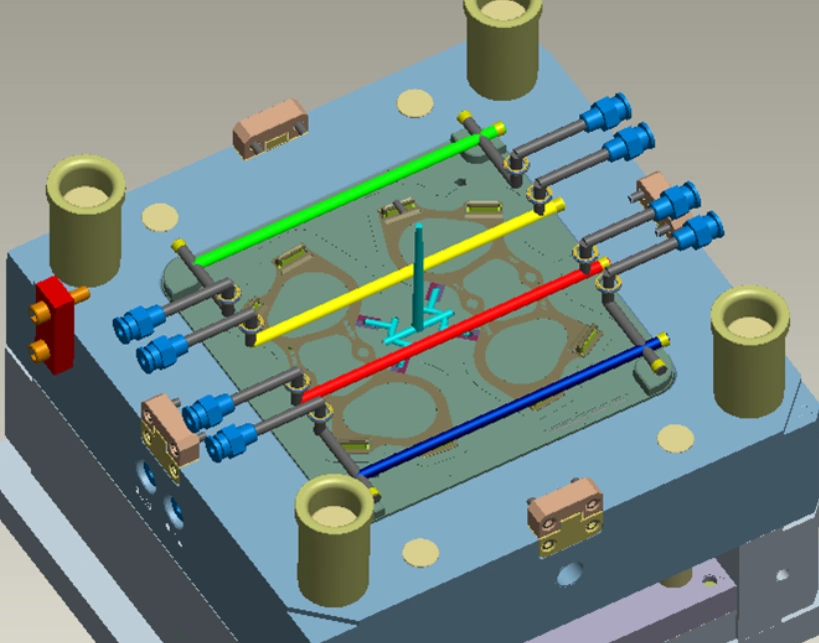
Injection molding cooling system
- Runner System Optimization – The runner layout can also be adjusted to enhance flow balance and reduce pressure loss.
- Gate Design Modification – A third method involves gate parameters – size, position, and type. It is an effective strategy for fixing weld lines and short shots.
Weld Line vs. Meld Line
It is important to differentiate between the weld line and the meld line. That’s because the similar visual appearance of the two convergence interfaces can give a misleading classification during inspections or failure analysis.
These melt front interface zones occur at the convergence of two melt fronts. However, for a weld line, the angle is relatively sharp – less than 135 degrees. The knit interface is also weaker due to the shallow molecular interdiffusion.
The formation of the meld line is more gradual. The pressure and temperature conditions are also more favorable. Its structural continuity is therefore stronger.
Despite the two flow interface lines being linear surface features, their structural properties differ significantly.
Weld Line Resolution Case Study
A weld line defect kept forming on a molded PC/ABS reusable endoscope handle. This triggered aesthetic and structural disqualifications. With a pinpoint gating on a three-plate mold, cyclical thermal stress was generated around the weld zone due to steam sterilization.
Analysis: The gating system was designed for balanced mold filling, not the control of weld lines. Since the convergence angle was minimal (below 40°), the bonding of melt fronts was poor. Due to the temperature sensitivity of ABS/PC, the weld lines at the convergence also became darkened.
Solution:
- Gate positions were redesigned to move the weld to an invisible, non-load-bearing section, alongside venting improvements
- A 15°C increase in mold temperature for a hotter flow front meeting point
- No tooling rebuild or material change was required
Takeaway:
Molded parts that undergo repeated sterilization can still experience latent failure even if the weld line passes the first inspection. The material’s contraction and expansion create stress, which first goes to the weak weld.
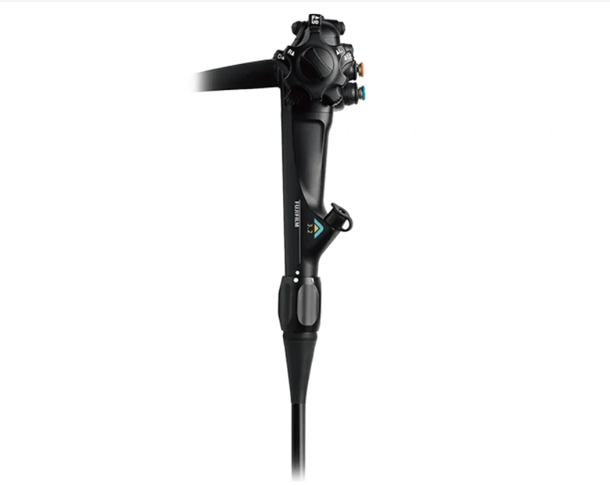
An endoscope handle
Try Prolean Now!
Conclusion
Injection molding weld lines may signify a surface blemish or structural weakness in a part. Processing conditions determine the presence and extent of these defects. Manufacturers should avoid weld lines, especially for enhanced appearance and strength of parts.
Our injection molding strategies minimize and avoid weld lines. The secret solutions include planned gate location, optimized part design, and well-thought-out material selection.
Upload your design or contact our experienced design team today to jumpstart the manufacturing process with our unparalleled injection molding service.
FAQ
What Is the Angle of a Weld Line in Moldflow?
In moldflow, the angle of a weld line refers to the convergence angle for the two flow fronts.
0 Comments