Precision Sheet Metal Bending
Sheet metal fabrication is the process of forming, cutting, bending, and joining metal sheets and turning them into components and functional parts. Examples of sheet metal fabrication include decorative panels in architecture and large riveted panels on the side of aeroplanes, showing custom sheet metal applications.
While sheet metal fabrication can seem a simple process, sheet metal manufacturers like Proleantech provide material guidance, advanced 8 sheet metal fabrication techniques, DFM support for high-volume sheet metal production, and access to top-of-the-line sheet metal fabrication machines.Read more:Precision Sheet Metal Fabrication
Sheet Metal Fabrication Process
Design
Good sheet metal fabrication starts with a practical design. Following basic design guidelines helps avoid production issues and makes sheet metal forming easier and more accurate. Below are the key design parameters to consider.
Material Thickness Uniformity
The sheet metal fabrication process requires a uniform thickness distribution because different thickness levels will cause uneven material deformation during sheet metal forming. The standard thickness range for materials extends from 0.5 mm to 6 mm, but any deviation above 5% will lead to bend fractures.
Bend Radii and Allowances
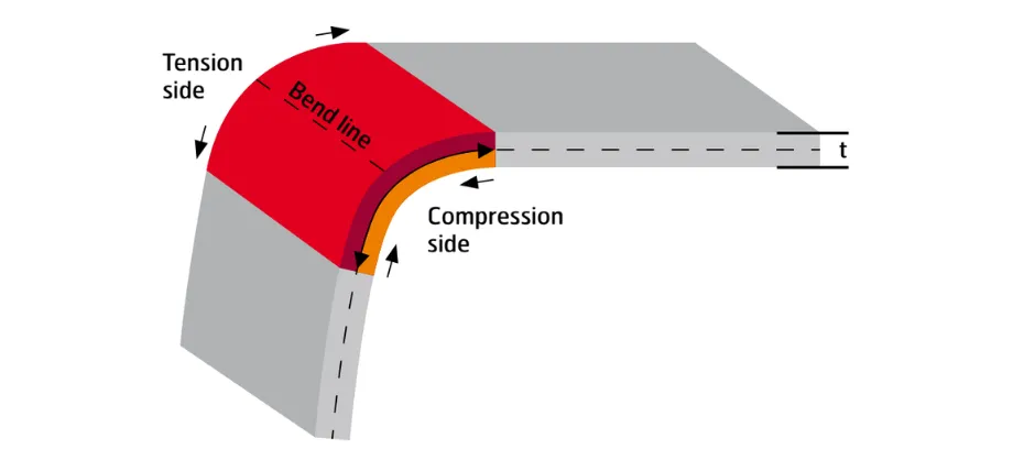
Sheet Metal Bend Stresses
In sheet metal fabrication, the minimum inside bend radius is generally equal to the material thickness (1t). This helps reduce cracking and excessive sheet metal stretching during bending. High-strength steels may require a larger bend radius to avoid material failure. The K-factor (typically 0.33) is then used to calculate the bend allowance using the following formula:
Allowance = π/180 × bend angle × (radius + K × thickness)
The calculation for a 90° bend on 2 mm aluminum with a K value of 0.40 results in an allowance of 3.5 mm.
Hole and Cutout Placement
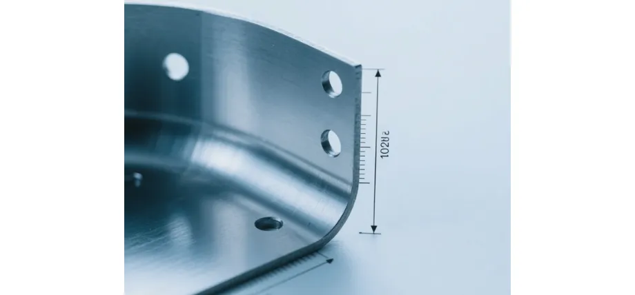
Precision Bent Component
In sheet metal fabrication, the distance between holes (created by sheet metal machining punch) and bend lines should be at least twice the material thickness to prevent shape distortion. Additionally, relief notches with a 0.5 mm radius should be added at these points. The minimum diameter for punching operations should be 1t, but laser or drilling methods are needed for smaller holes.
Angles and Tolerances
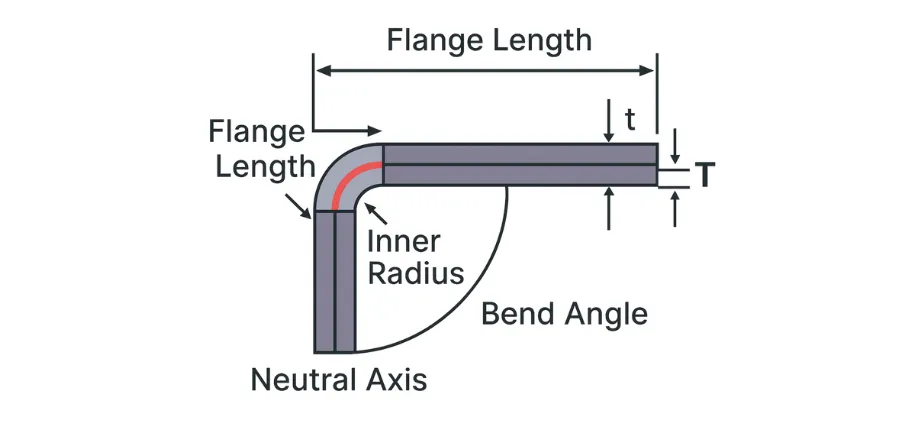
Bend Geometry Parameters
In sheet metal fabrication, the maximum bend angle for air bending should remain below 165°, as it helps control springback, which requires a 0.5–3° compensation through overbending during the sheet metal bending process.
The standard angular tolerance amount is ±1°, but users can achieve a precision of ±0.5° through coining operations. The overall part tolerance system, ISO 2768-m, specifies tolerances of ±0.1 mm for lengths shorter than 100 mm.
Feature Symmetry and Nesting
The design process should create features that mirror each other because this approach reduces tool rotation requirements. The design should include tabs for efficient nesting operations while aiming to use more than 85% of the material in nested flat patterns.
Material Selection and Preparation
In sheet metal fabrication, the selection of materials for sheet metal manufacturing depends on their mechanical properties, including yield strength, ductility, and corrosion resistance, while considering both environmental factors and loading conditions. The preparation begins with uncoiling and coiling, followed by leveling and cleaning to remove surface defects that could lead to forming failure.
- Low-Carbon Steel: Low-Carbon Steel requires annealing at 650°C after rolling to achieve ductility of over 20% elongation while maintaining its yield strength of 250 MPa.
- Stainless Steel 304: Stainless Steel 304 requires nitric acid passivation to remove free iron for achieving corrosion resistance while offering 205 MPa yield strength.
- Aluminum 5052: Forming process requires the greasing of the Aluminum 5052 material with alkaline solubilizers to prevent galling from occurring while its yield strength reaches 193 MPa.
- Galvanized Steel: Galvanized Steel coating contains 60–100 g/m² of zinc, which requires HCl pickling to remove and achieve uniform welding results.
- Copper C110: C110 requires bright annealing in hydrogen to preserve its high conductivity, which exceeds 100% IACS.
- Brass 260: The sheet metal drawing process for brass sheet metal fabrication is less prone to cracking when Brass 260 undergoes stress-relief treatment at 300°C while maintaining its yield strength between 100 and 150 MPa.
Related To: sheet metal design
Cutting and Shaping the Metal (cutting and shaping techniques subheadings)
Laser Cutting
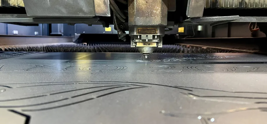
Laser Cutting in Action
The laser cutting in sheet metal fabrication utilizes high-power lasers that pass through optical systems to create heat, melt, or burn or vaporize materials, which makes custom cut sheet metal parts.
Gas assistance then removes molten debris from the cutting path. The cutting process uses CO2 beams for steel materials up to 20 mm thickness and fiber beams for steel materials up to 25 mm thickness while providing better control over reflective surfaces. The cutting process produces kerf widths between 0.1 mm and 0.3 mm, operating at speeds of 50–200 m/min for 1 mm aluminum sheets at 100 m/min. The system maintains a precision of ±0.05 mm while creating a heat-affected zone that spans between 0.2 mm and 0.5 mm.
The process allows nesting of parts, which results in less than 5% material waste. The process allows users to create intricate shapes within thin material layers.
Plasma Cutting
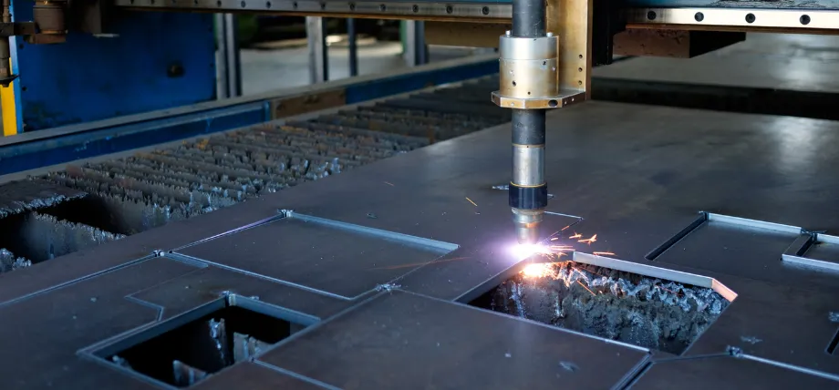
Plasma Cutting Process
Plasma cutting produces an electrically conductive plasma arc that reaches extremely high temperatures to cut materials, while compressed gas removes dross. The plasma arc reaches temperatures between 20,000°C and 30,000°C, which enables cutting of conductive metals up to 50 mm thick. Cutting process of 10 mm mild steel material at a speed of 0.5 mm/min while producing edge bevels between 1–3 degrees and surface roughness in the range of Ra 12–25 µm.
The equipment costs for plasma cutting remain lower than those required for laser systems. The process delivers exceptional performance when cutting thick plates that exceed 25 mm in thickness.
Waterjet Cutting
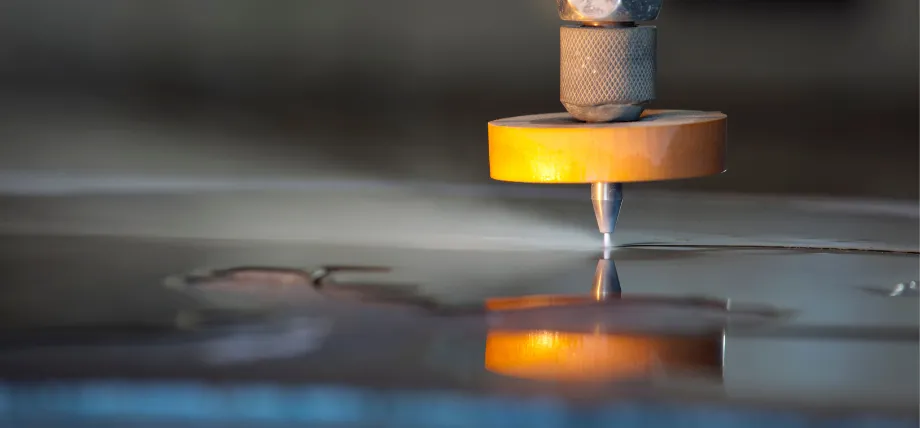
Abrasive Waterjet Cutting
The waterjet cutting process uses a water stream with abrasive particles that passes through a nozzle to cut materials without generating heat. The system operates at pressures between 300 and 600 MPa with garnet abrasive (80–120 mesh) to cut materials up to 200 mm thick. The cutting process of 10 mm steel material occurs at 0.5 mm/min while achieving ±0.1 mm precision and 0.1–0.5 degrees of taper, which needs CAD compensation.
The process produces no heat-affected zones to maintain the original material characteristics. The system works with sensitive materials that cannot withstand heat, as well as non-metallic substances.
Punching
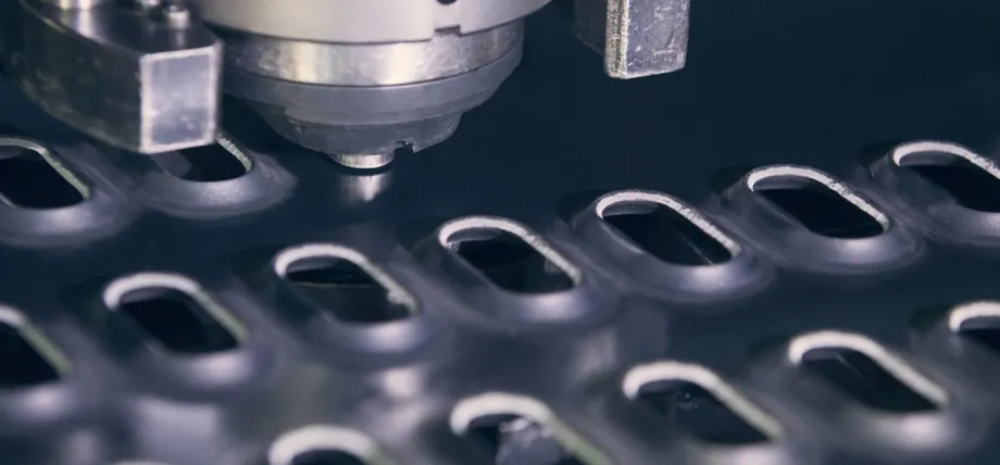
Turret Punching Operation
The sheet metal machining punch process in sheet metal fabrication uses a die and punch set inside a press to shear materials, which produces holes and sheet metal blanking at high speed. The hydraulic and servo presses operate at 500 strokes per minute to create holes that reach six times the material thickness, while producing less than 0.05 mm of burr, and last between 10,000 and 500,000 hits with carbide tools.
The sheet metal punch process in sheet metal fabrication operates at maximum speed when performing numerous identical tasks in large-scale sheet metal production. The process enables users to create multiple formed parts during each operating cycle.
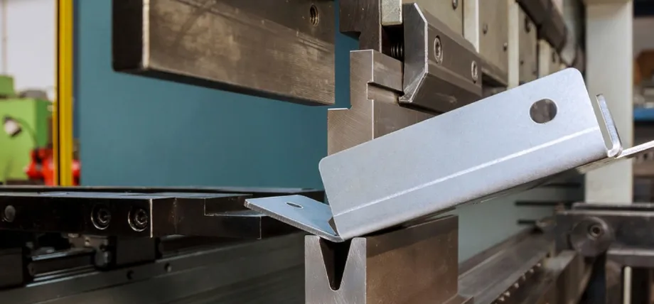
Forming and Bending
Press Brake Bending
The press brake bending process uses tonnage to push the sheet between the punch and die for angle formation through air bending, bottoming, and coining techniques. The equipment operates within a range of 50-100 mm while processing sheets of 3–4 meters in length, producing bend radii that start at 0.5 times the material thickness. The springback effect deviates angles by 0.5-3 degrees when working with aluminum, but the process requires 1–3 degrees of overbending to achieve ±0.5-degree precision in bottoming.
The process enables users to create bends with radii exceeding two times the material thickness through air bending operations. The system enables users to program sequences for producing complex multi-bend parts.
Roll Forming
Roll Forming Process
The process of roll forming uses sequential roller stations to transform strip material into its final profile shape. The production system operates at 10–30 m/min to process coils through up to 20 stations, which create channels and custom sections with ±0.5 mm cross-sectional tolerance for widths up to 1,500 mm.
The process allows manufacturers to produce extended lengths of more than 10 meters during continuous production. The process delivers uniform profiles while using minimal raw materials during production.
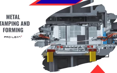
Stamping
The stamping process in sheet metal fabrication uses high-tonnage presses to operate with progressive or transfer dies, which perform synchronized cutting, forming, and trimming process operations. The process operates at 1,000 strokes per minute to produce 1,000 parts per hour for bracket production through the use of lubricants that maintain friction coefficients under 0.1 on materials ranging from 0.5 to 6 mm thick at draw ratios up to 2:1.
- The stamping process enables users to perform punching, forming, and trimming operations from a single production station.
- The process becomes cost-effective when sheet metal manufacturers produce more than 10,000 units.
Welding and Assembly
MIG Welding Assembly
MIG Welding
MIG welding operates by passing a consumable wire through a torch while an inert shielding gas protects the weld during continuous wire deposition. The process deposits 5–10 kg/hour of material at 200–300 A with wire feed speeds of 5–15 m/min, achieving 2–5 mm penetration in lap joints using Ar/CO₂ shielding gas. It is widely used in sheet metal assembly because it provides fast, consistent welds for a wide range of metal parts.
- The process enables the fast welding of steel structures between 1 and 20 mm in thickness.
- Welding enables automated seam production for consistent results.
TIG Welding
The TIG welding process employs a non-consumable tungsten electrode, which operates with a separate filler material while being protected by an inert gas shield. The welding process operates at 50–200 A to create heat-affected zones that are less than 1 mm wide, using base composition-matching fillers (e.g., ER316L) under pure argon protection.
- The process creates smooth welds with minimal distortion when working with thin stainless steel or aluminum materials.
- The process preserves corrosion protection in applications that require high precision.
Spot Welding
The spot welding process unites metal sheets through electrode resistance heating, which produces small nuggets at specific points. The welding process uses 5–10 kA current for 0.1–0.5 seconds to create 4–6 mm diameter nuggets under 2–5 kN force, which results in peel strengths above 3 kN.
- The process allows fast assembly of large numbers of parts in automotive manufacturing operations.
- The process eliminates the need for filler materials because it produces clean overlapping joints.
Brazing
The brazing process uses molten filler material, which flows through tiny spaces by capillary action to join parts without reaching the melting point of the base metal. The process of brazing requires temperatures between 600–800°C with silver alloys to create joints that achieve a shear strength of 100–200 MPa in gaps ranging from 0.05–0.2 mm, while using flux to prevent oxide formation.
- The process enables the connection of different metal materials while maintaining their original shapes.
- The joining process works best for lap or butt joints that experience shear forces.
Finishing
The finishing process enhances both surface quality and protective capabilities, while also creating a more visually appealing appearance. The finishing process requires specific adjustments based on the substrate material.
The deburring process eliminates burrs that exceed 0.1 mm in size. The process requires either tumbling or electrochemical methods. The process creates edge radii that measure 0.2 mm. The powder coating process creates a thin film that ranges from 50 to 100 microns in thickness via an electrostatic process. The curing process takes place between 180°C and 200°C.
The anodized surface of aluminum metal withstands salt spray tests for more than 1000 hours. The anodizing process for aluminum occurs through a sulfuric acid solution. The oxide layer grows between 10 and 25 microns during the process. The material achieves a hardness level of 300 HV.
Stainless steel material undergoes electropolishing treatment. The process removes surface material to a depth of 5-10 microns. The process enables achieving surface roughness below 0.4 microns for medical implant applications. (Read our guide to learn 14 sheet metal finishing methods for custom parts)
Try Prolean Now!
Custom Metal Fabrication Process: Design and Prototyping
Design rules for prototyping concentrate on manufacturing capabilities. The material will experience reverse bending stresses when bends exceed 180°; therefore, designers must maintain this limit. The simulation of flat patterns through CAD unfolding uses steel materials to calculate bend deductions between 0.4 and 0.5t for steel.
The use of 3D-printed dies for initial bends during hybrid prototyping enables engineers at Proleantech to test springback behavior, which is confirmed by finite element analysis (FEA) with mesh sizes of 1 mm or smaller. The prototype tolerance is maintained at ±0.05 mm during each iteration of soft tooling development.
CNC Machining (Sheet Metal Machining)
CNC Laser Cutting
CNC laser cutting uses G-code to control the laser beam path, while power modulation adjusts the cut for different material thicknesses. It operates at 50–200 mm/min with 2–6 kW fiber laser sources and autofocus control, maintaining ±0.1 mm focal length accuracy. This produces precise contours with 0.1 mm kerf widths, more than 90% nesting efficiency, and minimal distortion. It is widely used for sheet metal cutting where accuracy and complex profiles are required, while sheet metal shearing is often preferred for simple straight cuts.
CNC Bending
CNC bending uses servo-electric presses to perform programmed angle sequences. The system maintains ±0.01 mm back gauge positioning accuracy and supports 8-axis operation with tool changes in under 1 minute. It can produce hem depths of up to 10 mm while maintaining ±0.25° angle accuracy. These capabilities make it suitable for quick turn fabrication of complex sheet metal parts.
CNC Punching
CNC punching uses turret tooling to perform multiple feature operations in one setup. The system operates at 800 hits per minute with 20–40 tools, producing louvers, countersinks, and features in materials up to 6 mm thick with 360° automatic tool indexing. It also supports small production runs with different hole patterns while reducing secondary operations.
Materials For Sheet Metal Fabrication
Different types of sheet metal are chosen based on the required strength, corrosion resistance, and forming properties.
Low-carbon steel (1018) has a yield strength of 250 MPa and exhibits ductility, with 25% elongation, but requires a protective coating against rust due to its cost-effectiveness for building frames. Stainless Steel 304 and 316 are widely used for their corrosion resistance. Their 16–18% chromium content protects against rust, while 316 also contains 2–3% molybdenum for better performance in chloride environments. Their tensile strength ranges from 515–620 MPa. Aluminum 5052 has a density of 2.7 g/cm³, a 1t minimum bend radius, and a fatigue strength of 160 MPa, making it a good choice for forming operations, including sheet metal embossing.
The protective Zn coating on Galvanized Steel ranges from 20–100 g/m² to deliver 500–1000 hours of salt spray resistance, yet requires fume extraction during welding operations. The material properties of Copper C110 include thermal conductivity of 400 W/mK and antimicrobial properties; however, it softens at 200°C, which restricts heat-affected zone operations.
Brass 260 shows excellent machinability at 100% while offering water resistance, and its 8.5 g/cm³ density makes it suitable for fitting applications.
| Material | Density (g/cm³) | Tensile Strength (MPa) | Yield Strength (MPa) | Elongation (%) | Common Thickness (mm) | Key Applications |
| Low-Carbon Steel | 7.85 | 400–550 | 250 | 20–25 | 0.5–6 | Enclosures, brackets |
| Stainless 304 | 8.00 | 515–620 | 205 | 40–60 | 0.4–3 | Medical devices, exhausts |
| Aluminum 5052 | 2.70 | 228–310 | 193 | 12–25 | 0.6–6.3 | Aerospace panels |
| Galvanized Steel | 7.85 | 350–500 | 200 | 20 | 0.5–4 | HVAC ducts |
| Copper C110 | 8.96 | 220–280 | 70 | 45 | 0.3–3 | Heat exchangers |
| Brass 260 | 8.53 | 300–400 | 100–150 | 65 | 0.5–2 | Electrical connectors |
Common Sheet Metal Parts and Applications
Air Bending Operation
Automotive Industry
The body panels and chassis frames consist of stamped steel, which provides crash energy absorption while maintaining thicknesses between 0.7 and 1.2 mm. The 304 stainless mufflers in exhaust systems demonstrate resistance to temperatures reaching 800°C. The engine components use aluminum 6061 brackets and mounts, which achieve 40% weight reduction compared to cast-iron components.
Aerospace Industry
The fuselage skins consist of 2024 aluminum panels, which receive riveting for structural integrity, while maintaining a tensile strength of 450 MPa. The wing ribs consist of Titanium Grade 5 formed spars, which achieve maximum strength-to-weight performance through their 1.8 g/cm³ density. The turbine housings made from Inconel 625 material operate at temperatures reaching 1000°C.
Medical Industry
Surgical instruments are made of 316L stainless steel, a material that undergoes electropolishing treatment to achieve a Ra 0.2 µm surface finish. The imaging equipment and biocompatible medical devices use anodized aluminum housings that meet ISO 10993 standards for biocompatibility. The body temperature enables the Nitinol sheet to function as a stent material for implantables.
Costs of Sheet Metal Fabrication
| Factor/Method | Sheet Metal Fabrication (per part, 1000 units) | CNC Machining (per part, 1000 units) | Key Differences |
| Material Cost | $0.50–$2.00 (steel/aluminum) | $1.00–$5.00 (block stock) | Sheet minimizes waste (5–10% vs. 50–70%) |
| Setup/Tooling | $500–$2000 (dies reusable) | $200–$1000 (end mills, one-time) | Sheet metal has a higher initial cost but is economical for volumes >500 |
| Labor/Machine Time | $0.20–$0.50/min (laser/punch) | $0.50–$1.50/min (milling) | CNC is slower for thin parts |
| Total per Part (simple bracket) | $3–$8 | $5–$15 | Sheet 30–50% cheaper at scale |
| Tolerances Impact | ±0.1 mm standard (+10% cost for tighter) | ±0.01 mm standard | CNC cutting for precision increases costs |
How To Achieve Cost Efficiency in Sheet Metal Fabrication
Design Optimization
Use standard thickness levels between 0.8 mm and 1.6 mm to avoid additional costs for custom stock materials. The design should incorporate multiple functions to create fewer parts, which will shorten production time by 20-30%. The design for manufacturability (DFM) approach should be used to achieve more than 85% material utilization while keeping bending operations under eight per part to reduce production time.
Material and Procurement Strategies
Purchase coils in large quantities to receive a price reduction of between 10% and 15%, and select materials with pre-applied coatings to eliminate the need for additional finishing steps. The finite element analysis helps determine the correct material strength level, which enables the use of 304 stainless steel instead of 316 stainless when corrosion requirements allow, thus reducing costs by 15-25%.
Process and Equipment Efficiency
The implementation of multi-function CNC systems enables operators to perform cutting and bending operations simultaneously, which results in 40% less part handling. The system should perform predictive maintenance to achieve less than 5% downtime while following an operation sequence that starts with inner features to reduce setup requirements. The use of soft tooling and 3D-printed jigs for low-volume production reduces initial costs by 50%.
Quality and Waste Reduction
The simulation validation process helps reduce rework to less than 2% while achieving 90% scrap material recovery rates. Proleantech has well-trained staff with lean process optimization, which reduces storage expenses.
The company should use identical components throughout different projects to spread tooling expenses across larger production runs. The implementation of automated systems for repetitive operations leads to a 25-35% increase in production speed. The system should track two essential performance indicators, which include less than 5% waste generation and more than 95% operational availability.
Important Skills In Metal Fabrication
Sheet metal fabrication experts need to combine their technical knowledge with hands-on skills to achieve proficiency. The process of blueprint reading enables users to understand GD&T symbols, which results in feature alignment within ±0.05 mm positional tolerances. The low melting point of aluminum (660°C) requires welders to maintain TIG current levels below 150 A to prevent porosity formation.
The welding expertise includes choosing MIG wire types (ER70S-6 for steel) and creating proper joint preparations through 45-degree bevels to ensure complete penetration. CAD modeling software, SolidWorks, and AutoCAD enable users to add K-factors, which produce exact flat patterns. The CMM measurement system enables users to verify dimensions with precision within 0.01 mm accuracy. The 2000 CFM fume extraction system operates as a safety measure to protect workers from hexavalent chromium.
Problem-solving ability and collaboration are essential soft skills for springback compensation, particularly in the use of coining techniques and assembly sequence management. Application of CNC programming skills through G-code nesting programming leads to a 20–30% increase in production speed.
Related To: Sheet Metal vs Machined Parts: What is the Best Method?
Try Prolean Now!
Custom Sheet Metal Services
At Prolean Tech, we offer custom sheet metal services for aerospace, medical, electronics, and consumer products. We have state-of-the-art fiber laser cutting machines with 0.001” accuracy and CNC press brakes that provide forming of up to 400 tons.
Proleantech has certified welding engineers and welding robots for precision welds for high-volume orders.
Request a free quote today!
Conclusion
Sheet metal fabrication uses advanced CNC technology and air bending presses to produce precision, durable parts for various industries. Sheet metal fabrication also encompasses joining and fastening techniques, such as riveting and welding.
FAQ
What is Sheet Metal Fabrication?
Sheet metal fabrication is a fabrication technique that includes cutting, bending, forming, and welding thin metal sheets into finished parts, components, and enclosures.
I found process of creating sheet metal prototype very concise and clear . Could you please elaborate more regarding the step-by-step process of creating prototype?
@lekhnath. That was great to know. Sure, we will publish the article regarding the technical insights of creating sheet metal fabrication prototype. Please keep check our regular blogs. We publish three new articles every week.
Thanks for comprehensive and detailed of Sheet metal fabrication operation !