“CNC machining is a precise and automatically controlled technique for manufacturing prototypes in medium to bulk volumes. Despite its precision, errors are still associated with it. Product manufacturers must know their reasons and preventive measures to avoid these errors and achieve the desired results.”

The CNC machining processes, however, are precise and accurate, but they may lead to inaccurate outcomes when not employed appropriately due to tool wear and chip formation. This way, innovative techniques like the splitting process or embossing process play a vital role. These advanced techniques help avoid or prevent these nibbling defects, tool wear, and tear, as well as embossing defects. In some cases, the trimming process also appears more useful in eliminating these quality-impacting defects.
High-precision CNC machining factories create perfect parts or products from workpieces. Sometimes, these appear a significant challenge due to process imperfections or cnc machining defects. These challenges have been important as they have helped operators learn and improve their methods to get the best results. Identifying and analyzing CNC machining defects is always helpful, as this will help improve future machining operations.
Prolean Tech is a leading on-demand CNC machining factory in China. Based on their over a decade of experience, they have provided valuable information on the causes and remedies of machining defects. This blog post provides valuable insights about CNC machining defects, their impacts on products, and solutions to these potential issues, including deep drawing defects.
What Are CNC Machining Defects?
Common machining defects list
CNC machining defects are irregularities or failures in the end products that can be traced to the machining process. These imperfections may appear as a dent, scratch, or any other physical damage on the workpiece, dimensional inaccuracies, poor surface finish, defects in the material, broken cutting tools, and faulty machines. These defects may pose several issues in the final machined parts, such as dimensional inaccuracies, poor surface quality, and elevated temperatures.
Various factors may lead to machining defects during the cutting process, and they include the following; Chips, chatter, burrs, chipping, and built-up edges. These are typical defects associated with metal cutting and are found in all types of machine tools and processing methods, such as machining centers, CNC lathes, and automatic lathes.
Try Prolean Now!
Common Machining Defects
Let’s discuss some common machining defects.
Overcutting in Workpieces
Causes:
- Tool bending is due to low tool rigidity, long length, or small tool diameter.
- It might be due to operator error or improper handling of the food items.
- Inconsistent cutting allowance (for example, 0. 5 on the curved side surfaces, 0. 15 on the bottom).
- Some common cutting parameters that are likely to be set wrongly include tolerance, which is set to be too tight, and spindle speed, which is set to be very high.
Improvements:
- Tool Selection: To increase stability and strength, it’s essential to select large and short tools.
- Chamfering Program: To achieve a uniform allowance, it is recommended to use a chamfering program, which will allow the uniform removal of material on both side and bottom surfaces.
- Cutting Parameter Adjustment: Round corners with large allowances carefully and adjust the cutting parameters cautiously.
- Machine Speed Function (SF): Try to use the machine’s SF function, which allows operators to adjust the speed of the cutting operation for better results and precision.
Centering Issues
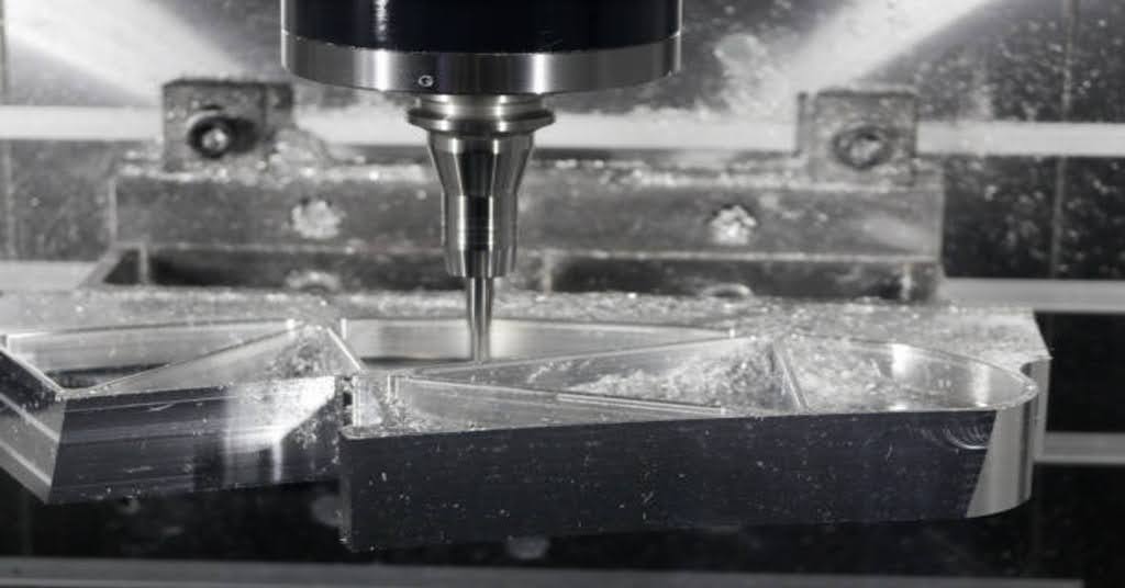
Machine centering
Causes:
- The centring issues may be caused due to operator errors and manual centring of lenses.
- Burrs or uneven surfaces on mold surfaces also impart centring issues.
- Usually magnetic centering rods sometimes lead to inaccurate parts designs.
- These issues also might happen due to the non-vertical sides of molds.
Improvements:
- Manually check the centring, and make sure the points are the same heights, and points are used.
- Try to remove any sharp edges or corners by using filling, or oils to clean the mold.
- Before the second batch of centering rods, try to demagnetize them. For this, you can employ non-magnetic materials such as ceramic rods.
- Vertically check your mold: The mold should be checked for its verticality using a dial indicator. If there are large discrepancies, talk to a fitter to rectify them immediately.
Tool Setting Issues
Causes:
- Manual tool setting is one of the main causes of operator errors during machine operation.
- Inappropriate tool clamping.
- The fly cutter’s tooltip is not accurate enough.
- Differences between R-cutters, flat-bottom cutters, and fly cutters.
Improvements:
- Consistent Manual Operations: Repeat the manual tool setting and do it correctly and precisely.
- Clean Tool Clamp: It is recommended that the tool clamp be cleaned using an air gun or rag before fixing the tool in its place.
- Accurate Measurement: To achieve high precision, use a single cutter tip on the fly cutter to measure the tool rod or base surface.
- Separate Tool Setting Program: Create a separate tool setting program to solve these problems with variations between various types of cutters, including R-cutters, flat-bottom, and fly cutters.
CNC Crash – Programming
Causes:
- If the safety height is not properly set, the tool may collide with the workpiece during a rapid feed (G00).
- The tool used does not correspond to the one described in the program sheet.
- The length of the tool (blade length) is not aligned with the machining depth on the program sheet.
- The depth values in the Z-axis mentioned on the program sheet do not tally with the actual measurements.
- Some of the mistakes that may occur include; incorrect coordinate settings during programming.
Improvements:
- Ensure the safety height is set above the highest point of the workpiece
- Make sure that the tool mentioned on the program sheet is the intended tool that was used.
- Record tool length and blade length correctly and ensure actual machining depth is measured.
- Check the Z-axis measurements carefully and ensure the values entered in the program sheet are correct.
CNC Crash – Operator Errors
Causes:
- The Z-axis depth setting of the tool is not correct.
- Some errors include centering and operation numbers, such as failure to consider the tool radius.
- Losing the die, dropping it, or taking it away mid-roll (e.g., rolling a D10 die when a D4 was needed).
- Making the wrong selection (for example, selecting A9. NC instead of A7. NC).
- Incorrect handwheel rotation, or turning it in the wrong direction. For instance, pressing it incorrectly during a manual rapid feed (X instead of -X).
Improvements:
- Set the Z-axis tool position (bottom, top, split surface, etc. ) very carefully.
- Also, check the centering and operations requirements.
- Keep the tool alignment right for the program sheet before fixing it.
- The programs must be run in the right sequence.
- Improve the level of handling the machines manually.
- Raise the Z-axis above the workpiece and then move it manually.
Accuracy In Smooth Curved Areas
Causes:
- If you’re getting rough surfaces on curved parts, here’s why:- If you’re getting rough surfaces on curved parts, here’s why:
- Setting up the wrong cutting parameters such as tool angle, and speed.
- The usage of blunt, and inefficient tools for a long time in the process.
- When tools are protruding or have too much clearance, issues arise.
- At other times, we are not cleaning the chips adequately or applying oil correctly.
- How we have set the machine to cut can also impact the level of smoothness.
- There may be some roughness on the workpiece in the form of burrs (small roughened areas).
Improvements:
- It is better to set cutting parameters that are more appropriate for smoother curves.
- Keep sharp tools, and replace them when they become blunt.
- Tools should be kept short and as close fitting as possible to reduce additional space.
- Adjusting the cutting speeds and the type of tools used is also important to get the best results.
- Eliminating chips, expelling air, and applying oil properly.
- Teach the machine to cut in a way that will assist in creating smooth curves.
Managing High Cutting Pressure
High cutting pressure is the force exerted on the cutting tool during machining. It happens when the tool is in contact with the workpiece and the material is being cut or machined away. This pressure is determined by tool geometry, cutting parameters, material characteristics, and the machining environment. High cutting pressure is associated with problems such as tool wear, machine stability, high energy consumption, and workpiece distortion.
How to Handle It?
- Adjust the cutting speed, depth, and feed rate to minimize the pressure while maintaining productivity.
- Employ cutting fluids or coolants to control heat, minimize tool wear, and prolong the life of tools.
- Introduce new technologies such as trochoidal milling to reduce cutting forces and increase the rate of production.
Variation or Irregularities In Surface Finish
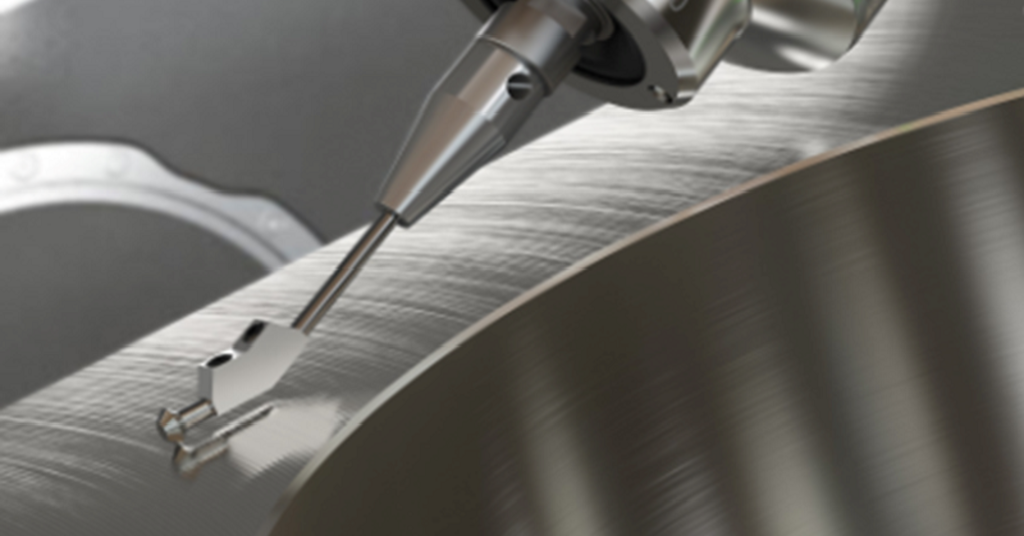
Surface roughness
Maintaining surface finish in CNC milling is critical in creating quality workpieces since it is a vital aspect of the final product. However, some factors may cause variations in the surface finish during the machining process.
One common problem is chatter caused by vibrations in the machine or cutter. This can happen when using a blunt tool, which leads to the tool cutting a large amount of material before the chip is removed, thus resulting in a poor surface finish.
Another factor is the type of CNC milling strategy used. Climb milling, where the tool enters the workpiece with a hit and exits slowly, usually results in a better surface finish. However, conventional milling, in which the tool rotates opposite the feed direction, tends to mar the finished surfaces and affect the final surface finish.
The selection and application of coolants also contribute to the process. Using proper coolants and lubricants can help avoid overheating and enhance the quality of the surface. On the other hand, if the cooling is insufficient, the tool wears out faster, and the surface finish of the workpiece is not as smooth.
To overcome different surface finish problems, it is important to keep cutting tools in good condition, select the right milling technique depending on the required surface finish, and use coolant properly during machining. With these solutions, CNC milling operations can attain better workpiece surface finishes.
Tool Wear or Marks
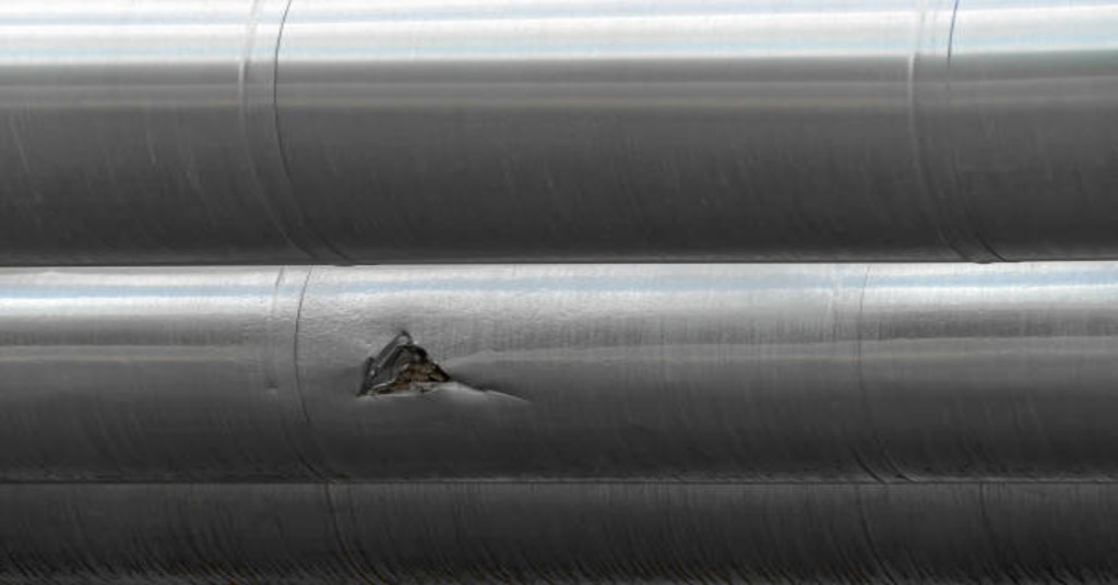
Metal crack
In CNC machining, tool marks dictate the visible lines or ridges left on the machined surface due to inaccurate contact between the cutting tool and the workpiece. These marks can appear for several reasons:
- Incorrect tool selection: Tool marks may arise due to high cutting parameters, improper tool selection, or defective material utilization.
- Machine vibration: Conditions and setup within the machine may cause these vibrations, which lead to marks on the surface.
- Tool entry and exit strategy: It’s important to consider how the tool comes into contact with the workpiece and how it leaves during the machining process because these aspects can affect the left-behind marks.
Improvements:
- Optimize Cutting Parameters: Reduce the pressure with which the tool is applied and further regulate the tool’s speed to reduce the marks left behind.
- Choose the Right Tools: Use tools with the right geometries and coatings that will not easily scratch the surface.
- Implement Finishing Operations: As a last step, grinding or polishing is applied to remove the remaining tool marks and enhance the general surface finish.
Delamination Issues
Laminated materials may delaminate during CNC machining. This means that the layers may separate or peel apart from the surface.
Cause:
- High cutting forces or high feed rates during the machining process.
- Laminated materials of poor quality or those which need to be more adequately bonded.
- Lack of proper choice of tools or using blunt tools.
- Lack of proper clamping or support may cause vibration or movement.
Improvements:
- Minimize cutting forces and select the appropriate feed rates.
- Use well-bounded laminated materials.
- Select fine cutting tools and instruments for laminated materials.
- Ensure adequate support and clamping to reduce vibration and movement.
Try Prolean Now!
Alternatives to CNC Machining Technique and their Respective Defects
However, CNC machining is more accurate and precise than traditional part manufacturing processes. Various alternate techniques are used, such as injection molding and metal casting. Even though these conventional methods are quite popular for large volume production due to their cost-effectiveness. But, they also exhibit deficiencies during the process. Let’s discuss their corresponding defects.
Some examples of welding defects include;
- Porosity
- Overlap
- Spatter formation
- Cracks
- Undercuts
Similarly, examples of casting defects include;
- Runouts
- Warping
- Metal penetration
- Slag Inclusion
- Hot tears
Moreover, injection molding, however, is cost effective for large runs, but risks, and inaccuracies are there. Some injection molding defects include;
- short shots
- vacuum voids
- Flow lines
- Jetting
- surface delamination
- sink marks, etc.
Key Takeaways
- Although CNC machining is a computerized technique, it can not be 100% accurate all the time, as inaccuracies still exist. These machines can be subjected to defects in terms of tool wear, breakage, nibbling effects, etc., that may impact the strength and quality of the end-use product.
- To eliminate or rectify these consequences, consider the appropriate machining process, tools, and workpiece material for optimal results.
- It’s imperative to understand the relationship between the tool and the machined material to identify related defects that may appear, and thus help minimizing those defects to save extra costs on projects.
- Moreover, it’s crucial to monitor machine efficiencies regularly, and readjustments are necessary for improving the quality of the parts in CNC machining.
FAQs
Q1. What are some of the most frequent issues observed in CNC machining?
Some common defects are roughness of the surface, wear of the tools, dimensional inaccuracies, chatter marks, and poor surface finish.
Q2. What are the ways of identifying defects in the CNC machining processes?
Some of the ways that can be used to identify defects include; visual inspection, measurement of dimensions using appropriate tools, surface roughness testing using metrology instruments, and monitoring of machine characteristics for any signs of anomaly.
Q3. Examples of Laser cutting defects.
CNC cutting, although more accurate in providing high-quality, smooth cuts and shaped parts, has potential risks. Some laser cutting defects include kerf deviation, dross, and variations.

0 Comments