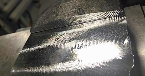
A defect on CNC machined part.
CNC machining defects are unwanted errors that compromise the quality of machined parts, often caused by factors like chip formation, chatter, chipping, excessive burrs, and built-up edges. The most common causes include complexity in the technical drawing, wrong tool arrangement, inappropriate machining conditions, operator expertise, and poor handling.
These issues can lead to dimensional inaccuracies, surface finish problems, tool breakage, machine downtime, and safety hazards. The root cause typically lies in improper cutting conditions, tool geometry, or machine setup, and recognising chip types or vibration patterns often helps diagnose these problems.
It’s essential to use appropriate tools and materials to prevent defects, ensure proper cutting speeds and feeds, and maintain machine stability. Regular tool inspection, effective chip and burr management, and using the right lubricants also play a crucial role.
Ultimately, understanding how materials behave under specific machining conditions allows for better defect control and improved product quality.
Get a CNC machining quote today — reduced costs & delivery to 30+ countries guaranteed!
This article will briefly discuss common CNC machining defects, reasons for defects, and possible solutions to avoid those defects.
What is Meant by CNC Machining Defects?
The CNC machining defects refer to any undesirable results and failures in finished products from the machining process. It includes physical damage to the workpiece, dimensional errors, poor surface finish, material defects, tool breakage, machine malfunction, and many more.
Poor machining defects might cause several minor failures in the final result of machined parts. It can cause a dimensional error, low-quality surface finish, heat build, and many more problems.
The fundamental causes of machining defects in cutting are chips, chatter, burrs, chipping, and built-up edge. Since these defects are generated by “cutting metal with a tool“ the mechanism of defect generation does not change even if the type of machine tool or processing method changes, such as machining centers, CNC lathes, and automatic lathes.
Let’s discuss the CNC machining defects by categorizing them based on the root of these problems, chips, chatter, burrs, chipping, and built-up edge.
Related:
The Impact of Tool Wear on CNC Machining Defects
Defects by Chip Formation:
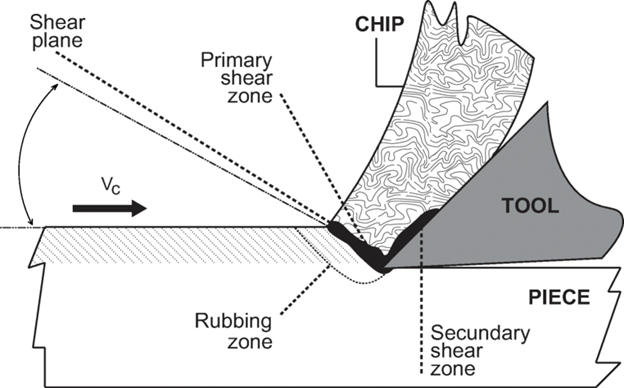
Chip formation mechanism
A chip is the debris or material created when a cutting tool removes material from a workpiece. Chip formation is an integral part of subtractive manufacturing because that’s how material removal occurs to convert the raw material into the desired shape.
Chips need to be removed smoothly & continuously. If they cannot be adequately removed, they will lead to machining defects and momentary stoppages, so it is necessary to discharge them reliably.
There are various types of metal chips: Splattery powder, continuous, discontinuous, curled, stringy, long spirals, and more. Since the shape changes depending on the machining method and the workpiece, it is no exaggeration to say that you can tell the machining quality by looking at the chips.
Flow-type chips are ideal, and the type of chips can indicate the machining state. On the other hand, discontinuous chips are considered problematic in CNC machining.
How Can We Ensure that Chips Cause Machining Defects
The following indications suggest the possibility of machining defects caused by chips:
- Chips wrap around tools and excessive chips in the machining area.
- Chips are being caught when changing the workpiece.
- If the cutting tool breaks unexpectedly, it could indicate that chips are causing defects.
- If the machining process is frequently stopping or experiencing unexpected downtime.
- Drill breakage due to chip clogging during drilling.
Prevention
- Use sharp and adequately maintained cutting tools. It will reduce the force needed to cut the material, which helps prevent chips from forming.
- Use appropriate cutting speeds & feed rates. If you cut too slowly, the tool will rub against the workpiece, creating heat and potentially causing chips. Also, cutting too quickly can restrict the removable rate because it will not be able to remove the material fast enough.
- Use chip breakers and chip removal tools.
Defect by Chatter
Chatter is an intermittent vibration that occurs during machining. It can be classified into two types, “forced chattering” and “self-excited chattering,” depending on the source of the vibration.
Forced chattering refers to the vibration caused by external forces acting on the machining system, such as an Imbalance in the cutting tool & workpiece, unstable machine foundation, inaccurate work holding, poor rigidity of the machining tool, and inaccurate posting. The entire batch of manufactured workpieces could be defective by chatter (Chirag Kulkarni, 2017).
There are several factors that can contribute to forced chattering, including:
-
- Machine spindle: The spindle of the machine can be the source of vibrations that lead to chattering if it is not running at the correct speed or if it is not properly balanced.
- Tool holder: A tool holder that is not designed correctly or is worn can cause vibrations that lead to chattering.
- Cutting conditions: High cutting speeds, high feed rates, and high depths of cut can all contribute to chattering.
- Workpiece properties: Hard or brittle workpiece materials can be more prone to chattering than softer materials.
To reduce or eliminate forced chattering, the following strategies can be used:
-
- Balance the machine spindle
- Use a higher-quality tool holder
- Use a cutting tool with a larger radius
- Use a more robust cutting tool material
- Use a cutting fluid
- Use a chatter-damping tool holder
- Use a more stable and robust machine
- Use a softer workpiece material
- Use a chatter suppression controller
Self-excited chattering is a phenomenon that occurs in machining processes when the cutting tool vibrates uncontrollably, causing a reduction in surface finish and an increase in tool wear. It is considered to be a self-excited vibration because it is caused by the interaction between the cutting tool and the workpiece, rather than an external source.
There are several factors that can contribute to self-excited chattering, including:
-
- Cutting tool geometry: Certain tool geometries, such as a tool with a small radius, can make the tool more susceptible to chattering.
- Cutting conditions: High cutting speeds, high feed rates, and high depths of cut can all contribute to chattering.
- Machine conditions: Loose or worn machine components can lead to vibrations that can cause chattering.
- Workpiece properties: Hard or brittle workpiece materials can be more prone to chattering than softer materials.
To reduce or eliminate self-excited chattering, the following strategies can be used:
-
- Reduce cutting speed and feed rate
- Use a cutting tool with a larger radius
- Use a more robust cutting tool material
- Use a cutting fluid
- Use a chatter-damping tool holder
- Use a more stable and robust machine
- Use a softer workpiece material
- Use a chatter suppression controller
Chattering leads to poor machining but also damage to the machine. The defects of chattering in CNC machining include workpiece deformation, poor dimensional accuracy, low-quality surface finish, tool breakage, safety issues, and more. Therefore, urgent countermeasures are required to prevent this defect.
How Can We Ensure That The Machining Defects are Caused by Chattering?
The following indications suggest the possibility of machining defects caused by chattering:
-
- A noticeable vibration in the machining process with a loud rhythmic noise.
- Degradation in the surface finish of machined parts
- Damage to machine and tools
- Reduce machining accuracy.
- Surface defects on the workpiece, such as scratches or pitting.
Prevention
-
- Apply the tool with a positive rake angle, which can prevent chattering by reducing the cutting forces.
- Ensure that the foundation of the CNC machine is stable.
- Ensure that there is no looseness or play in the setup.
- Maintain the perfect tool alignment Tool with a chamfer or a rounded edge can reduce the risk of chattering by absorbing the vibrations.
Defects by Chipping
Chipping refers to material removing the workpiece in small chips or fragments that occur on a cutting tool’s cutting edge. It almost always occurs during cutting work, but early detection is important because even small chips can lead to unexpected machine stops and damage to CNC machining operations.
The fundamental reasons for defects caused by chipping include insufficient tool strength, high cutting forces, inappropriate tool path & geometry, and hardness of the workpiece,
How to ensure the machining defects are caused by chipping?
The following indications suggest the possibility of machining defects caused by chipping.
- Frequently stopping or experiencing unexpected downtime of the CNC machining process.
- A rough-uneven surface finish with a dull, satin-like appearance.
- Excessive wear on cutting tools
- Poor productivity or low-machining cycle time.
Prevention:
- Consistently maintain and sharpen your cutting tools and ensure their condition so that they can produce clean chip-free cuts.
- Use a tool with a hard coating, such as a diamond or carbide.
- Utilize a tool with plenty of cutting edges. It will uniformly distribute the cutting forces and lower the possibility of chipping flaws.
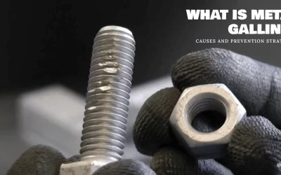
Defect by Excessive Burrs
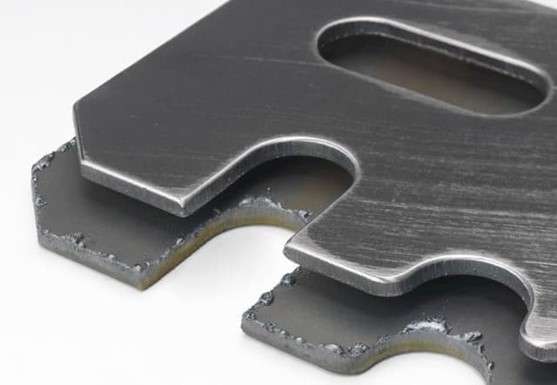
Excessive burrs in a CNC machined part.
Burrs refer to the tiny, sharp projections or edges left on the surface of a machined part. These are basically the protruding parts of the work that are left uncut, and chips pushed out. It is no exaggeration to say that cutting processes always generate burrs ranging from large to small burrs.
Leaving burrs as they are can cause troubles and injuries in the following process, so processing that suppresses the generation of burrs and reliable deburring is essential.
Poor surface finish is the primary defect in the formation of burrs during CNC machining. Other defects include low- product quality, increased scrap and waste, and increased production time.
How to Ensure the Machining Defects Caused by Excessive Burrs?
The following indications suggest the possibility of machining defects caused by excessive burrs:
- Visible burrs on the machined surface.
- Rough surface with a lot of imperfections.
- Poor fit and function
- The outflow of defective products.
Prevention
- Use the appropriate cutting tool according to the material you are machining.
- Consider the deburring tool to remove the burrs created during machining.
- A tool with a longer nose radius might prevent the burr defects.
Defects by The Built-up Edge
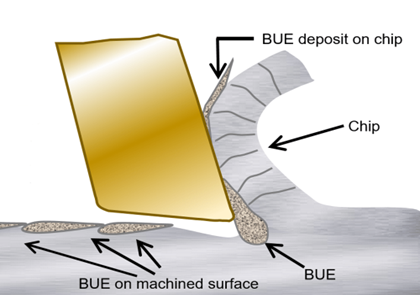
Built-up edge (BUE)
Built-up edge is a phenomenon in which chips adhere to the tip of the cutting edge due to high cutting pressure and frictional heat.
The main reason for built-up edges is Inappropriate cutting speeds & feed rates, inappropriate coolant or lubricant, and poor tool conditions & geometry. In addition, some materials are prone to built-up edge problems, such as ductile materials that are easily work hardened (mild steel, brass, stainless steel, aluminum, etc.), which tend to generate a built-up edge.
The built-up edges result in poor fit & function, rough surface finish, safety issues, and dimensional inaccuracy.
How Can the Machining Defects Caused by Built-Up Edges be Ensured?
The following indications suggest the possibility of machining defects caused by built-up edges.
- Cutting-edge chipping
- The visible presence of built-up edges on the workpiece.
- Unexpected machine downtime.
- Poor fit and function
Prevention:
- Use a tool with a damping coat or a damping geometry.
- Apply appropriate lubricants and coolants.
Tips to Avoid All Types of CNC Machining Defects.
Since some common mistakes can lead to various defects in CNC machining operations, there are a few fundamental tips to avoid these effects.
Know your material
Always check that you are using a proper setting and lathe for the type of metal in question. Consider the several physical & mechanical properties of workpiece material before the selection of tool material & geometry. In addition, apply the appropriate cutting speed & feed rate according to the material type.
For example, with very-hard metals, your lathe may not be able to work, as is the case with cast iron. So, consider the model and specifications equipment before programming.
The care and dedication of your team are essential at this time, but you also need to have a partner to assist you in predictive, preventive, or corrective maintenance cases.
Cross-check the digital instructions
When entering the code, the most common mistake with CNC machining is a simple spelling or syntax error. Although most modern lathes have mechanisms that prevent breakdowns, a simple detail like this can stop the entire production chain, damaging your equipment (10 Common Problems with CNC Machine Tools, 2021). Therefore, cross-checking of G-code is essential.
Periodic and preventive maintenance of equipment
It is essential to have a team of highly qualified professionals for the repairs and maintenance of your CNC machine. Maintain periodic & scheduled maintenance up to date, including services that improve equipment performance, such as:
- Lubrication of moving parts
- Checking and replenishing fluid levels
- Extraction or replacement of filters.
Summing Up
Countermeasures against machining defects are not limited to on-site ingenuity. Acquire a wide range of knowledge, from metal materials to tool characteristics, and take countermeasures.
At Prolean, our CNC experts have many years of experience in CNC machining. And they know exactly how to avoid machining defects. This way, the lead time and the quality of parts can be guaranteed.
If you are looking for any CNC machining service for your project, please feel free to contact us. We will get your production plan and quote in a few hours.
FAQ’s
What is the life expectancy of CNC?
With proper maintenance, CNC machines typically last 10 to 15 years, though high-end models can exceed 20 years. Usage frequency, workload, and servicing schedules significantly impact lifespan.
What is basic maintenance in a CNC machine?
Basic CNC maintenance includes daily cleaning, lubricating moving parts, checking fluid levels, tightening loose components, and inspecting tools for wear to prevent breakdowns and ensure precision.
CNC Machining Cost Comparison?
CNC machining costs vary by material, design complexity, and quantity. Aluminium is cheaper than titanium; 3-axis machines are more affordable than 5-axis. CNC is cost-effective for prototypes and mass production.
How can CNC machining defects be resolved?
CNC defects can be resolved by optimizing tool paths, using sharp tools, maintaining proper feed rates, and ensuring calibration. Regular inspections and operator training also help reduce machining errors.
What are the most common causes of CNC machining defects?
The most common causes of CNC machining defects include complexity in the CAD model, wrong tool arrangement, inappropriate machining conditions, operator expertise, and poor handling.
What are the most Common CNC machining defects?
There are several CNC machining defects, but they can be categorized as chips defects, chatter defects, chipping defects, burrs defects, and built-up edge defects.
How to prevent common CNC machining defects?
It can be prevented according to the specific type of defects. However, some common strategies include considering material properties, correct G-code, Periodic & preventive maintenance of equipment, and appropriate machining variables.
So nicely described! Could you pleased give more information’s regarding how syntax error can cause the machining defects? Are there any fixed relation between syntax and machining defects?
it significantly influence the machining quality but there is no such fixed mathematical relation
Although there is no mathematical relation . There is a simple relation between syntax errors in CNC programming and machining defects. Incorrect syntax can result in undesired tool paths, leading to defects like improper depths, offsets, or even tool collisions. While there’s no fixed mathematical relationship between syntax errors and defects, the accuracy of CNC code directly impacts the quality of the finished product. Proper code validation and simulation can prevent such issues.
thanks for your insights ! Appreciated it
Definitely the built-up edges produces various machining defects. I have experienced that
As a mechanist, I really enjoyed reading this article. How can I recognize the self-excited chattering? are there any specific signs??
Thanks Raj for your comment !
Recognizing self-excited chattering in CNC machining involves identifying specific signs such as:
1. Audible Noise: Chattering produces a distinctive, irregular noise that is different from the usual sound of the machine at work.
2. Surface Finish: The machined surface will have a wavy or rippled pattern, indicating uneven cutting due to vibrations.
3. Tool Wear: Excessive or abnormal wear on the cutting tool, often with visible marks or damage, is another indicator of chattering.
4. Monitoring these signs can help you identify and address chattering, thus ensuring better machining quality and tool life.
Greetings! Very useful advice on CNC defects within this article!
It is the little changes that will make the
most significant changes on machined parts quality. Thanks a lot for sharing!
Thank you!