Milling techniques vary widely, from face milling, to surface refinement to end milling for designing intricate shapes, by offering reliability, and precision in products.
Milling machines are used in metal-cutting industries; there is a rotating cutter to cut metal on a CNC machine. These cutters operate at high speeds for cutting metals, and the cutting periphery defines the intended amount of material to be machined. Milling machines are designed to accept more than one cutting tool at a time, making them more versatile than other CNC operations. They are very useful in workshops because of their precision and efficiency and can cut through metal faster than shapers, planers, or standard lathes. This article provides valuable information on 15 types of milling. Let’s get started!
Types of CNC milling machines
Before going into CNC milling techniques, let’s be familiar with various machines. CNC milling machines have evolved remarkably, diversifying in capabilities and purposes. Different milling machines cater to diverse production needs, each with unique features and functionalities.
1.Vertical Milling Machines
Often recognized as the most common type, vertical milling machines have vertically oriented spindles. This orientation means the cutting tool moves up and down, aligning with the machine’s vertical axis. Turret mills and bed mills primarily characterize vertical mills. Turret Mill contains a stationary spindle and a table that moves in both directions; the table moves only in the perpendicular direction to the spindle’s axis.
Vertical machines are generally preferred for their versatility. They are instrumental when dealing with individual pieces and small batch sizes. Whereas the table moves only in the perpendicular direction to the spindle’s axis in
2.Horizontal Milling Machines
As the name suggests, these machines have horizontally oriented spindles, compelling the mounted cutting tools to move left and right. Horizontal milling machines are particularly adept at Heavy-duty cutting and handling more significant pieces of material. These machines often come equipped with multiple cutting tools, enabling them to execute several tasks simultaneously.
3.Knee-type Milling Machines
These machines owe their name to an adjustable knee-like structure supporting the worktable. This design facilitates vertical movement and adjustments of the work table. Some noteworthy features include
- A robust design, ideal for heavy milling.
- Capability to handle various operations ranging from simple tasks to complex procedures.
Knee-type milling machines are incredibly versatile and are the backbone many manufacturing setups.
4.C-Frame Milling Machines
These are more robust than knee-type milling machines and are usually used in industrial settings. Their heavy-duty nature is defined by “A single-column design provides greater rigidity and larger working area for handling significant operations.”
5.Planer-type Milling Machines
Characterized by a dual motion capability, these machines have a table that moves linearly while the cutting operation remains stationary. Highlights of this type include Handling several workpieces concurrently and the ability to handle larger tasks with ease and precision.
6.Special Milling Machines
Specific tasks demand a unique approach. Enter the world of special milling machines. These are designed for specific tasks, such as:
- Rotary Table Machines: Designed for circular cutting operations.
- Drum Milling Machines: Crafted for camshaft and die production.
- Tracer Controlled Machines: Suitable for intricate designs and reproducing models.
Now, let’s move to six primary CNC milling techniques in detail.
Try Prolean Now!
Explore 15 Common Types of Milling
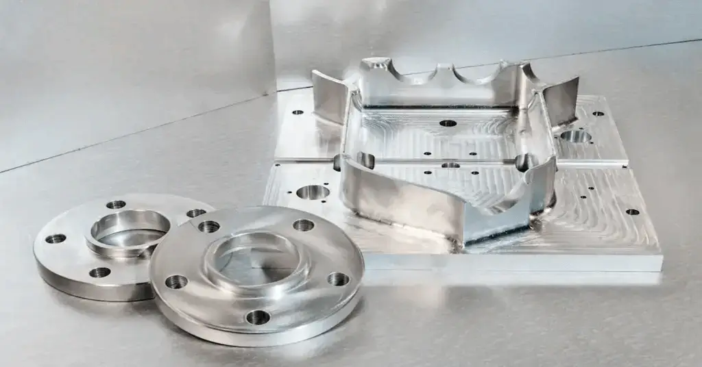
CNC milling is one of the advanced machining techniques involving essential tools employed in high-quality production activities due to its high surface finish and accuracy. Milling machines are of various types, each designed for a particular milling process. Below are some of the most critical types of milling.
Slot Milling
Slot-milled precision parts
Slotting Milling is a form-cutting operation in which a slot or channel is removed from the job material. This is done using appropriate cutting tools, such as end mills or slotting cutters, to cut slots in the material. These tools are employed to create slots of different dimensions. Slot cutters are available only inside positions, while end mills can be used inside and at end positions. Therefore, slot milling makes blind slots that start from a hole.
In addition to functional grooves, CNC milling is also used for marking and branding. Text milling is commonly applied to engrave letters, symbols, and logos on machined parts.
Thread Milling
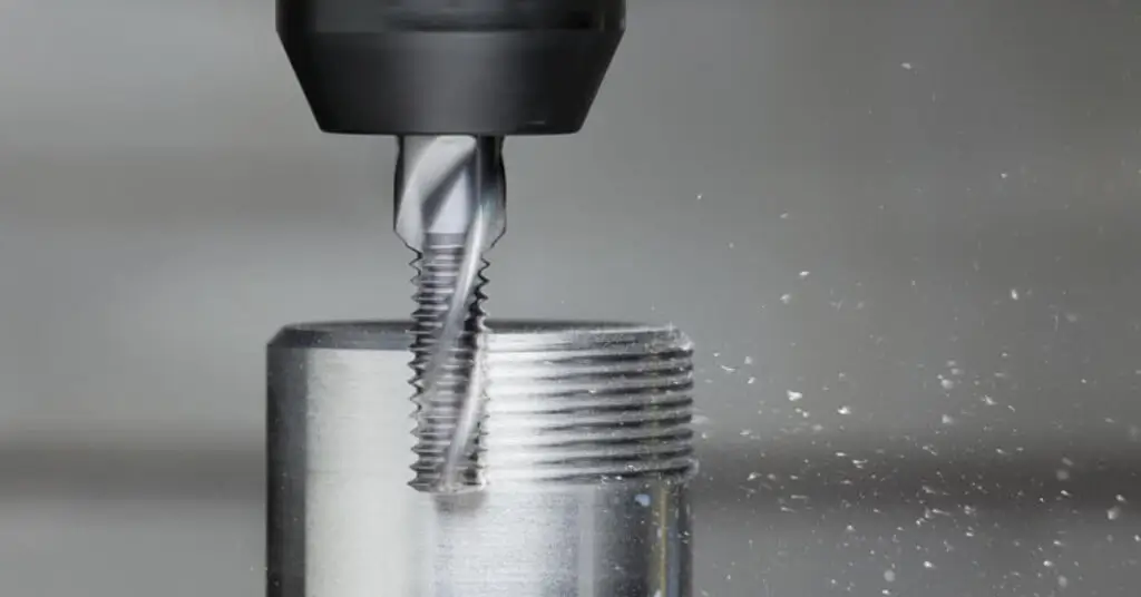
Thread milling
Thread milling is a process of cutting threads on the workpiece with a sharp-edged cutting tool. This tool is employed similarly to taps or dies but is more versatile in producing various thread forms and increasing tool life. Thread milling is applied where high accuracy and strength of threads in a given part or component are needed.
Table: Thread Milling Parameters
| Parameter | Typical Value | Remarks |
| Cutting Speed | 50-150 m/min | Depends on the material. Harder materials typically require slower speeds. |
| Feed Rate | 0.2-0.6 mm/tooth | Based on thread pitch and tool size. |
| Thread Tolerance | ±0.002 mm to ±0.01 mm | Precision is often dictated by the industry’s demands and the CNC machine’s capabilities. |
Face Milling
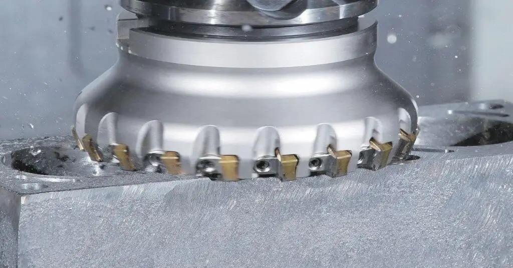
Face milling
The face milling process entails cutting; in this process, a tool known as a face mill with a flat cutting edge is used to cut the material. Subsequently, the tool is dragged over the surface to be flattened to create a smooth, flat surface. This technique is suitable for flat and wide areas like engine blocks and metal plates, but slanted regions can also be made depending on the position of the tool’s arbor. Read more:Face Milling vs Peripheral Milling
Table: Snapshot of machining parameters for face milling
| Parameter | Ideal Range | Remarks |
| Cutting Speed | 50-200 m/min (metals) | Varies based on material; higher speed might reduce the finish |
| Feed Rate | 0.1-0.5 mm/tooth | Faster feeds can accelerate wear |
| Depth of Cut (axial) | 1-5 mm | Deeper cuts might compromise the finish |
| Depth of Cut (radial) | 1-20 mm | Broader cuts can introduce more heat |
Profile Milling
Profile milling
Profile milling is a unique process used to produce various forms and edges on the required surface of a given material. This method uses a tool with more than one edge; it has a ball-shaped end and works along a set path. The ball-ended tool is most useful when removing sharp edges, which the corners of other tools may have. Several machine axes generally outline the required shape, and some operations may be performed with fewer axes. This technique is widely used in molding and tooling industries and manufacturing parts with intricate surface shapes. Profile milling is popular among types of milling for its high dimensional accuracy and precision. Therefore, it is applied to create complicated forms. Another area of use for CNC machines is profile milling because this type of machine can manage several axes, which is difficult to manage manually. Read more:Diamond milling
Table: Snapshot of machining parameters for profile milling
| Parameter | Ideal Range | Remarks |
| Cutting Speed (Metal) | 50-220 m/min | Optimized based on the material’s hardness, more rigid materials demand slower speeds. |
| Feed Rate | 0.03-0.5 mm/tooth | Predicated on the cutter’s size and material being milled. |
| Profile Tolerance | ±0.005 mm to ±0.03 mm | Precision hinges on the application; intricate profiles often demand tighter tolerances |
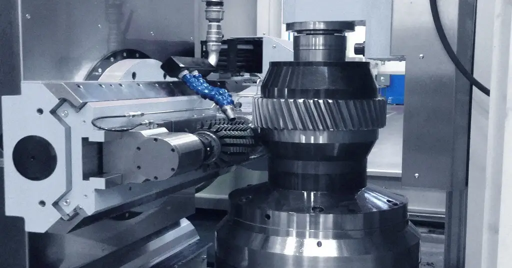
Gear Milling
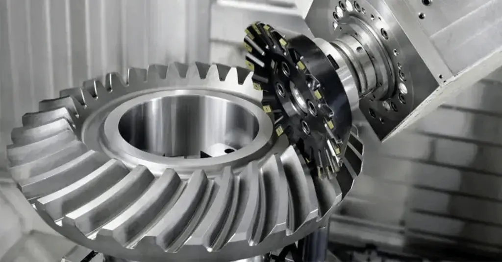
Gear-milling
Gear Milling – a particular type of milling operation in which gears or teeth of gears are generated with the help of gear cutting tools such as gear hobbing cutter or gear milling cutter. This method is critical, especially in the automotive and machinery industries, where the formation of gear teeth is essential for transmitting power and directing movement. It is possible to mill gears on CNC and manual milling machines, producing numerous gears, including spur, helical, and bevel gears. Read more:Helical Milling
Shoulder Milling
Shoulder milling is a method of cutting material off the side or shoulder of the workpiece. This is done with a side cutter, which shaves material to give a flat shape per the design. Shoulder milling effectively creates the right size of shoulders and steps in several parts and details.
Saw Milling
Sawmilling uses a cutter with a large diameter and several teeth around the circumference to shave a workpiece into thin plates or parts. These tools, resembling circular saw blades, can cut in various modes: to machine the material in a direction across or along the axis in a conventional or climb milling manner. They are also known as slitting wheels, but the process is known as slitting instead of sawmilling.
Side Milling
A side milling milled the job piece from the sides with the help of a milling cutter or an end mill. It is used in making shapes, flat surfaces, or forming shapes such as slots, grooves, or pockets.
Gang Milling
Gang milling involves mounting several cutting tools on the same spindle, including the end and slab mills. This allows some operations to be performed simultaneously, thus improving the machining and efficiency rate. Gang milling can mill out shapes and thin sections of material such as engine crankcases, transmission cases, etc., and is helpful in parts that have to perform multiple operations in one cycle, such as injection molding.
Angle Milling
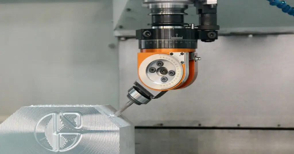
Angle milling
Angle milling is a process of machining features on a workpiece at an angle with the cutter axis. The workpiece is placed on an angle plate or fixture so that unwanted material is cut off to the required size. This method helps develop features such as chamfers, bevels, slots, and, to some extent, dovetail slots. It mainly produces components with a constant cross-sectional or cross-sectional profile.
Table: Snapshot of machining parameters for angle milling
| Parameter | Ideal Range | Remarks |
| Cutting Speed (Metal) | 60-250 m/min | Adjust based on material hardness; softer metals might require slower speeds. |
| Feed Rate | 0.05-0.4 mm/tooth | Influenced by material and cutter type |
| Angle Tolerance | ±0.05° to ±0.1° | Precision is crucial, especially in joinery and precision components |
Form Milling
Form milling employs cutters with edges that have form relief; these cutters have a geometry similar to the required form. These form mills use the cutting tool to rotate the workpiece to produce forms that can penetrate each other on the workpiece. For example, form milling can produce turbine blades or make one component of a specific model of a definite product. The cutter has the right design shape that must be cut and prepared for further use.
Straddle Milling
Straddle milling is used where the workpiece has two flat surfaces at right angles, and both are milled at once. This is made possible by having two or more side cutters on the same arbor since these are expected to be cut simultaneously. It is most suitable for making parallel slots, grooves, and other high-accuracy profiles. Some of the milling applications include the production of jigs, fixtures, brackets, automobile parts, and many more.
End Milling
End milling is one of the most common machining techniques. It employs a cylindrical cutting tool with teeth around the cutter’s circumference. It is suitable for producing fine features like slots, grooves, and other features on the workpiece. The end mill can also cut at an angle across the surface of the material being worked upon. It also recommends that the process have a smooth finish and that cutting on the various surfaces be precise.
For ultra-precision components such as medical micro-parts, micro molds, and electronics, micro milling is widely used to achieve extremely small feature sizes and tight tolerances.
CAM Milling
CAM milling is employed to manufacture CAM parts that convert motion in mechanical systems. This process utilizes a diving head tool to swivel the workpiece and remove material to the necessary CAM form. CAM milling is also applied to generate correct and advantageous CAM outlines for mechanical systems and equipment.
Peripheral Milling
Peripheral milling removes material along the sides of a workpiece, as opposed to the surface. The operation is ideal for precision edges, reducing stock thickness, and creating slots over the length of a part. Using helical teeth on the cutter helps to reduce cutting forces and provides a cleaner finish.
Try Prolean Now!
Comparison of Different CNC Milling Techniques
The nuances between each milling method are significant, influencing decisions from tool selection to operational parameters. While some techniques prioritize surface finish, others emphasize the intricacy of design or the creation of specific geometries. The table below presents a comparative overview, shedding light on the unique attributes and applications of six pivotal CNC milling techniques.
Table: Comparison of Various CNC Milling Techniques
| Milling Techniques | Primary Application | Strengths | Common Materials Used | Tooling Essentials | Challenges & Considerations |
| Face Milling | Surface finishing & flattening | Efficient material removal; smooth surface finish | All metals; Plastics | Cutter with multiple teeth; larger diameter | Need for precise leveling; potential for tool wear |
| Angular Milling | Creating angled surfaces & edges | Precise angular cuts; versatile designs | Metals; Hardwoods; Plastics | Single-angle milling cutters or double-angle milling cutters | Calibration for angle; material constraints |
| Pocket Milling | Recessed areas & cavities | Accurate depth control; efficient material removal | All metals; Plastics; Hardwoods | End mills; specialized pocket milling tools | Complex tool paths; potential tool breakage |
| Profile Milling | External periphery & contouring | Producing complex shapes; precision detailing | Metals; Hardwoods; Plastics | Ball end mills; rounded or specialized tips | Complex tool paths; material considerations |
| Contouring with CNC milling | Detailed contours & 3D shapes | High precision; aesthetic allure | Metals; Plastics; Aerospace alloys | Ball end mills; diverse profile tools | Speed & temperature management; intricate tool paths |
| Thread Milling | Internal & external threads | Precision threads; superior finish | All metals; some plastics | Thread mills; helical tools | Tool wear; high machine requirements |
How To Choose the Right Type of Milling Process?
Automobile gearbox face, end, and gear milling are some of the complex and critical manufacturing processes. All have input in the last part; therefore, the right approach to the project must be used. Here is how to make the right decisions for milling operations
1. Material Type
The type of material being used in a specific project is a critical factor in the milling operations to be carried out. Some material characteristics are hardness and thermal conductivity, which determine its machinability. For instance, tool steel is among the materials that are difficult to work with when applying conventional milling methods. To achieve the best result for the tool and the material, ensure the selected operation is suitable.
2. Desired Finish
The other consideration that one has to make when choosing a milling operation is the degree of surface finish. They all offer surface roughness, determining the part’s finish and purpose. Choose an operation based on the required value of roughness (Ra) of the final product:
- Face Milling: Ra 0.8 – 3.2 μm
- End Milling: Ra 0.8 – 6.3 μm
- Slot Milling: Ra 1.6 – 6.3 μm
- Thread Milling: Ra 1.6 – 3.2 μm
- Gear Milling: Ra 1.6 – 3.2 μm
3. Geometric Complexity
Not all types of milling are ideal for fine feature production. The fundamental milling operations are Face, Slot, and Plain milling. These are the most appropriate for shapes without curves, while the others are the end, thread, and gear milling appropriate for shapes with curves. Consider the detail level in the design and cnc milling applications and determine if the chosen operation can cope with it.
4. Machine Parameters and Settings
Parameters like spindle speed, feed rate, and depth of cut define your milling machine’s performance. The most critical factors in the machining process include spindle speed, feed rate, and depth of cut. These factors also include the finish, surface finish, and machining speed. Ensure that the machine has the right features that correspond to the milling operation you will use. However, it should be rigid and work-holding set up to meet the operation’s requirements.
5. Choosing the Right Cutter
Milling can be of many types, each needing a different cutter. A proper cutter should be used to achieve the right results and not harm the tool or the workpiece. For instance, in end milling operations, the tools used include flat end, ball nose, or corner radius cutters. Ensure that you can get a cutter appropriate for the type of milling you wish to conduct.
Conclusion
Selecting the right CNC milling china company for the milling processes is very crucial for the optimal outcomes of your milling project. However, all types of milling have their advantages and can be applied to some geometries and finishes. Prolean Tech provides customized CNC milling, including design improvement, various milling options, and polishing processes. Our quality control department is always ready to ensure all the parts meet your specifications. Contact us today for our quotation and start your CNC milling service with Prolean Tech.
0 Comments