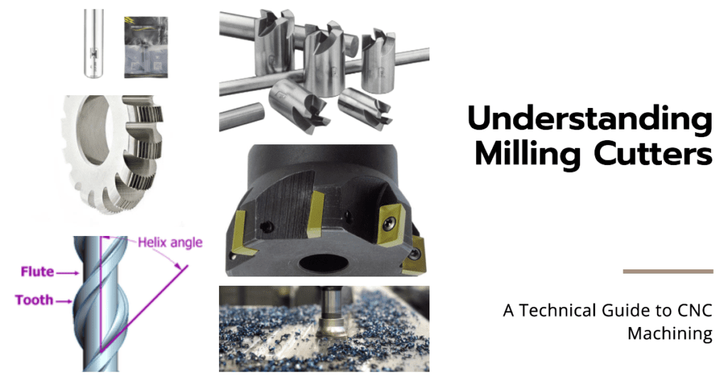
Milling cutters, the rotary cutting tools typically used in milling machines or machining centers, serve as the backbone of CNC machining. These specialized tools are designed to remove material from workpieces, resulting in precision parts and components. Different types of milling cutters are used depending on the nature of the operation – such as face milling, profile milling, or slot milling – and the material being machined. Understanding these tools, their operation, and how to calculate their RPM (Rotations Per Minute) for optimal performance is vital in the world of CNC machining.
In this comprehensive article, we will explore the wide spectrum of milling cutters and their functionalities in CNC machining processes. So, let’s dive deep into the dynamic realm of milling cutters and discover how they’re shaping the future of manufacturing.
Breaking Down Milling Cutters: An Essential CNC Tool
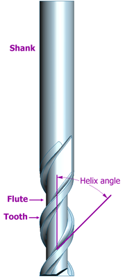
Milling cutters, by design and function, hold a special place in the world of CNC machining. They come in various shapes, sizes, and materials, each configured for a specific task in the milling process. A detailed breakdown of the key components of a milling cutter includes:
- Body: The body is the central part of the cutter that houses the cutting edges. Depending on the application, it can be manufactured from high-speed steel, cobalt steel, carbide-tipped, or solid carbide, with the diameter typically ranging from two to four inches.
- Flutes: The flutes are grooves or channels in the cutter body, designed to allow chips to exit during the cutting process. More flutes translate to a slower feed rate but a smoother cut, while fewer flites allow for a higher feed rate but a rougher cut.
- Cutting Edges or Teeth: The cutting edges or teeth perform the actual work of slicing through the workpiece. The geometry and placement of these edges – whether straight, helical, or staggered – have a significant effect on the performance and functionality of the cutter.
- Shank: The shank is the part of the cutter that is held in the tool holder of the milling machine. It must be robust and precisely made to ensure the cutter rotates true and doesn’t introduce vibration into the process.
Table 1: Key Components of a Milling Cutter
| Component | Description |
|---|---|
| Body | Holds the cutting edges; can be made from various materials |
| Flutes | Channels in the cutter body for chip removal |
| Cutting Edges or Teeth | Perform the actual cutting operation |
| Shank | Held in the tool holder of the machine |
Diving into Types of Milling Cutters
Milling cutters come in various shapes and sizes, each designed to perform specific types of milling operations. The choice of the cutter is determined by both the type of material being milled and the specific milling operation to be performed.
Now, Let’s take a detailed look at some common types of milling cutters:
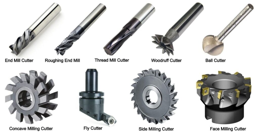
1. End Mills
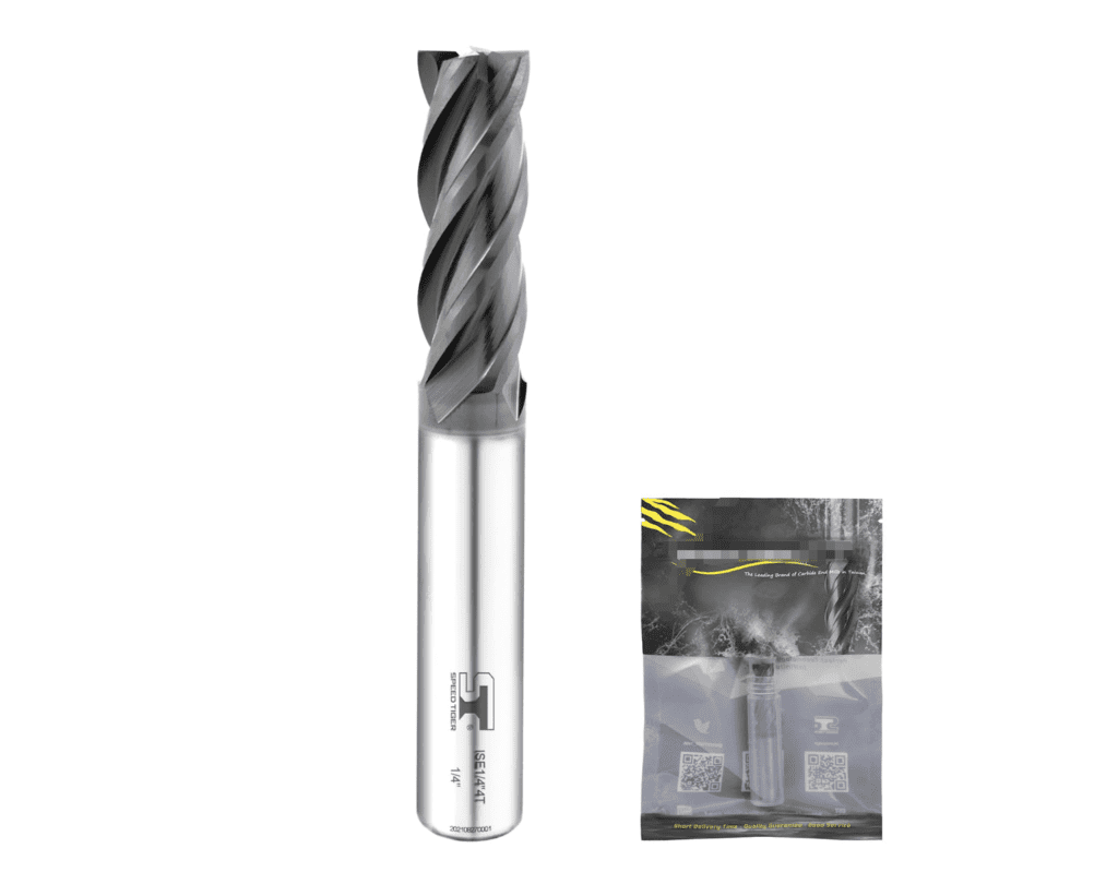
End mills are the most commonly used type of milling cutter. They are named after their ability to cut from both the end and the sides of the tool. End mills are ideal for slotting, profiling, and plunging operations. Their design enables them to create a variety of shapes, making them a versatile choice for many applications.
There are many types of end mills, including square end mills for creating flat-bottomed grooves and slots, ball end mills for milling rounded slots or complex contours, and roughing end mills, which are designed with serrations to efficiently remove large amounts of material.
2. Face Mills
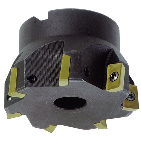
Face mills are used for facing operations where the goal is to create a flat or squared surface. The cutting edges of these mills are located along the outside perimeter of the tool, with the cutter typically larger than the workpiece width. This allows for a large surface area to be worked on in a single pass. Face mills often feature indexable carbide inserts of varying sizes, shapes, and grades to accommodate different materials and finishes.
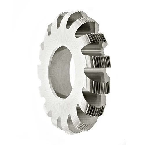
3. Slab Mills
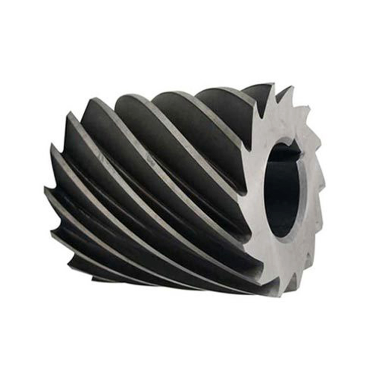
Slab mills are designed for wide, flat surface cutting (or slabbing) and general-purpose machining. The teeth of a slab mill are arranged on the outer edge of the cylinder, allowing for the tool to operate at high speeds and remove material efficiently over large surface areas. Slab mills are often used in heavy-duty operations where a large amount of material needs to be removed quickly.
4. Fly Cutters
Fly cutters are a type of milling cutter that uses one single cutting blade. The large, smooth arcs created by these cutters are used for finishing surfaces to a high degree of smoothness and accuracy. The single blade of the fly cutter, set at an angle to the workpiece, cuts with a slicing action that leaves a smooth surface. The width of the cut is adjustable, allowing the user to size the cutter to the workpiece.
5. Form Milling Cutters
Form milling cutters are special tools designed to mill specific shapes into a workpiece. They can cut curves and contours in the piece, or create shapes such as dovetails, T-slots, and other specifically-shaped grooves or indents. These tools are often custom-made to meet the requirements of specific jobs, making them invaluable for custom work.
6. Hollow Mills
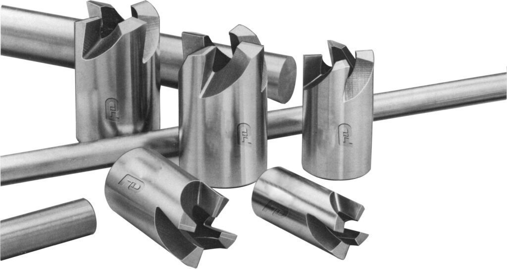
Hollow mills are a type of cutting tool used to cut a hole into the surface of a workpiece or to enlarge existing holes. Similar in appearance to a drill bit, hollow mills remove material from the inside of the workpiece, leaving a hollowed-out area. They are often used in tandem with other types of milling cutters to create complex shapes and features.
Plasma Cutter Miller: A Modern Marvel
An evolution in the field of milling, the plasma cutter miller is a versatile and efficient tool, widely appreciated for its accuracy and efficiency. Unlike traditional milling cutters, a plasma cutter miller employs a high-velocity jet of ionized gas or plasma to cut through electrically conductive materials. It’s particularly useful in situations where high precision is required, or where the material in question is resistant to conventional milling techniques.
The process begins when an electric arc forms within the gas, typically air, which is then forced through a small nozzle orifice inside the torch. This arc ionizes some of the gas, thereby producing a highly focused, heated, and directed beam of plasma that slices through the material, melting it away.
The capabilities of the plasma cutter miller can be broken down as follows:
- Speed and Efficiency: Plasma cutters are considerably faster than traditional milling cutters, capable of cutting up to 500 inches per minute.
- Precision: With advancements in technology, modern plasma cutters can achieve a cut accuracy of up to ±0.01 inches, matching the precision of many laser cutters.
- Versatility: Capable of cutting a broad range of metals, including steel, stainless steel, aluminum, brass, and copper.
- Ease of Use: Plasma cutters require less skill to operate than conventional milling cutters, and the machines often have built-in safety features.
RPM Calculation for Milling Cutters: Maximizing Efficiency
In milling operations, calculating the correct RPM (revolutions per minute) for the milling cutter is crucial to achieving optimal cutting speed and prolonging the cutter’s lifespan. The RPM is calculated based on the cutter’s diameter and the speed of the material being cut, known as the cutting speed.
The formula used to calculate the RPM is as follows:
RPM = (Cutting Speed * 4) / Diameter of the Cutter
For instance, if the cutting speed for mild steel is 100 feet per minute and the diameter of the cutter is 0.5 inches, the RPM would be:
RPM = (100 * 4) / 0.5 = 800
It’s essential to remember that these calculations are a guideline and may need to be adjusted based on the specific machine, material, and cutting conditions. A higher RPM isn’t always better, as it can cause overheating and wear on the cutter. Conversely, a lower RPM may not cut effectively and may leave a poor surface finish.
Example of RPM Calculation;
| Cutter Diameter | Cutting Speed (Feet per Minute) | RPM |
|---|---|---|
| 0.5 inches | 100 | 800 |
Understanding and correctly implementing the RPM calculation is pivotal in achieving maximum productivity and maintaining the lifespan of the milling cutter. This delicate balancing act between speed, efficiency, and durability is an integral part of successful milling operations.
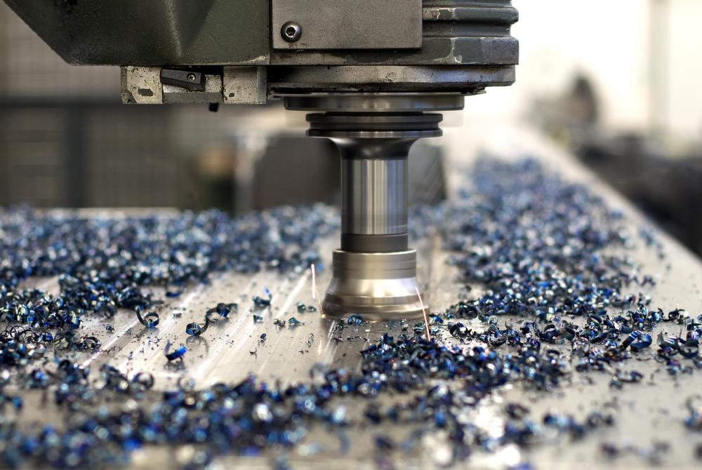
CNC Milling Cutters: Precision at Its Best
CNC milling cutters
Computer Numerical Control (CNC) milling cutters represent a significant advancement in the realm of milling technology. As the name implies, CNC milling cutters are controlled by computer systems that provide a high degree of accuracy and consistency in operations.
With CNC technology, milling cutters can be manipulated in three-dimensional space with extreme precision, making it possible to create intricate shapes and designs that would be nearly impossible with traditional, manual methods. CNC milling cutters are typically used in production where a high level of consistency is required across multiple parts, such as in the automotive or aerospace industries.
A few benefits of CNC milling cutters include:
- Consistency: The computer-aided process allows for consistent, repeatable precision.
- Speed: CNC milling machines often operate at faster speeds than manual milling machines.
- Complexity: Capable of creating complex shapes and designs.
- Automation: The process requires less human intervention, reducing the risk of human error.
Table 2: Benefits of CNC Milling Cutters
| Feature | Description |
|---|---|
| Consistency | Allows for consistent, repeatable precision |
| Speed | Operates faster than manual milling machines |
| Complexity | Capable of creating complex shapes and designs |
| Automation | Less human intervention, reducing human error |
Miller 375 Plasma Cutter: Power and Portability
The Miller 375 plasma cutter is a compact yet powerful tool known for its portability, ease of use, and exceptional performance. This plasma cutter’s compact design and relatively lightweight make it ideal for operations where mobility is a key factor.
Despite its small size, the Miller 375 packs quite a punch. It is capable of cutting through conductive materials, including steel, stainless steel, aluminum, brass, and copper, up to 3/8 inches thick. Moreover, the built-in inverter technology ensures clean and precise cuts with minimal dross.
Table 3: Key Features of the Miller 375 Plasma Cutter
| Feature | Description |
|---|---|
| Portability | Weighs just 19 pounds |
| Cutting Capacity | Can cut through materials up to 3/8 inches thick |
| Inverter Technology | Ensures clean, precise cuts |
| Durability | Built to withstand challenging conditions |
Is there Any Role of Milling cutters in End-part Tolerances?
Yes, the milling cutter indeed plays a crucial role in achieving the desired tolerances in a machined part. Tolerance in machining refers to the permissible limit of variation in the physical dimensions of a finished product. The type of milling cutter used, its size, material, and cutting conditions all contribute to the overall accuracy of the machining process and the final part produced.
Each milling cutter is designed to perform a specific type of milling operation, and the choice of the cutter can significantly influence the accuracy and finish of the machined part. A well-chosen milling cutter that is appropriate for the job and correctly installed can help achieve high precision in the milled part and minimize deviations from the specified dimensions.
Table 4: General tolerances offered by different milling cutters types
| Milling Cutter Type | Typical Dimensional Tolerance (in mm) |
|---|---|
| End Mills | ± 0.01 – ± 0.05 |
| Face Mills | ± 0.02 – ± 0.05 |
| Slab Mills | ± 0.02 – ± 0.07 |
| Fly Cutters | ± 0.01 – ± 0.05 |
| Form Milling Cutters | ± 0.01 – ± 0.04 |
| Hollow Mills | ± 0.02 – ± 0.06 |
Note: The values in the table are approximations. The actual tolerance achievable can vary depending on multiple factors such as the quality and condition of the milling cutter, the stability of the milling machine, the properties of the workpiece material, and the cutting conditions (speed, feed, coolant, etc.).
Milling cutter geometry, the material of the cutter, and its coating (if any) also play an important role. For instance, a cutter with sharp cutting edges and a high-quality coating can reduce the cutting forces, thus reducing the chances of part deformation and achieving better dimensional accuracy.
Prolean’s CNC Milling Services: Expertise and Precision
In the complex world of milling operations, having a trusted partner can make a significant difference. Prolean’s CNC milling services offer unparalleled precision, efficiency, and consistency. Our advanced CNC milling cutters and expert operators ensure that your project is executed to the highest standards.
From prototyping to full-scale production, our CNC milling services can handle a wide variety of materials and project sizes. We offer a comprehensive range of milling cutters, including end mills, face mills, slab mills, and more, catering to diverse operational needs. With Prolean, you can be confident that your project is in expert hands.
Conclusion
Milling cutters, in all their variety, are a testament to human ingenuity and the pursuit of precision. From their humble beginnings to the modern, CNC-operated variants, these tools have reshaped industries and made possible feats of manufacturing that were previously unimaginable. As we continue to innovate and strive for efficiency and precision, the humble milling cutter will undoubtedly continue to play a central role in our manufacturing endeavors.
FAQs
What is a milling cutter?
A milling cutter is a rotary cutting tool, typically attached to a milling machine, used in machining operations to remove material from a workpiece.
What is a CNC milling cutter?
A CNC milling cutter is a computer-controlled cutting tool used in CNC milling machines. These cutters can create complex shapes with a high degree of precision.
What is a Miller 375 plasma cutter?
The Miller 375 plasma cutter is a portable plasma cutting system known for its lightweight, ease of use, and exceptional cutting performance.
How do you calculate the RPM of a milling cutter?
The RPM of a milling cutter can be calculated using the formula: RPM = (SFM x 3.82) / Diameter, where SFM is the cutting speed of the material and Diameter is the size of the milling cutter.
What services does Prolean offer?
Prolean offers a range of CNC milling services, catering to a variety of materials and project sizes. Our services are distinguished by precision, efficiency, and consistency.

0 Comments