CNC machining
The cycle time in CNC machining refers to the time required to complete one or more machining operations. For any CNC machining project, cycle time is crucial to analyze the lead time and minimize the cost of particular parts or end products.
It influences the overall cost of CNC machining projects and other elements like material type, complexity, and precision. Calculating cycle time involves solving mathematical relations for operations such as milling, turning, drilling, etc.
This article will briefly overview cycle time computation for various CNC machining operations, the impacts of production cycle time & its reduction approaches.
Calculation of Production Cycle Time
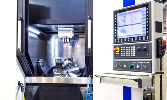
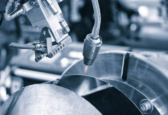
Estimation of cycle time in the control panel
The machining time is similar to the other times, and the ratio of distance traveled by the tool is the same as the speed. The general machining time for all operations, including milling, turning, facing, and many others, can be expressed mathematically as follows (Unit 5 Machining Time Calculation, 2012).

Where,
L= machining length of a workpiece (mm)
N= revolution of the workpiece per minute (rpm)
= 1000* cutting speed (V)/π*Diameter (D)
f= Feed rate (mm/min)
f=feed per revolution=feed per tooth * number of teeth = 0.1 * 20 = 2mm,
This mathematical expression gives a simple idea about machining time and how much time is required to machine a particular workpiece. You can also check the video below for a better explanation of the calculation of Machining cycle time. In addition, please feel free to download the Cycle Time Calculation Spreadsheet for your own project.
How to calculate cycle time in Excel
Cycle Time for Different Operations
1. CNC Milling
As was already explained, the general formula T=L/f*N is used to compute the cycle time for every CNC machining process. However, each case’s approach to calculating the variable might differ.
In the milling operation, the feed rate is calculated in terms of feed rate per tooth. It requires many teeth, cutting edges, or flutes on the tool.
Feed rate (f) = feed per tooth * number of teeth
Length = Job length + Tool over Travels x Number of Passes + Tool approach length.
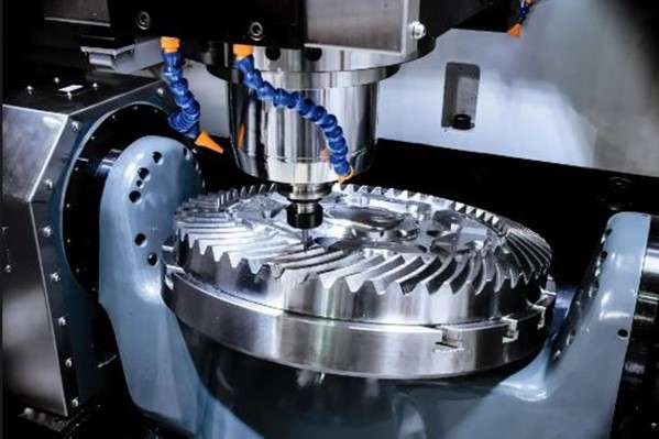
CNC milling operation
For Example, the machining length for a milling operation with a depth of cut of 4mm, workpiece length of 200 mm, cutter diameter of 200mm, tool approach & over travel distance of 4 mm, feed rate per tooth 0.2 mm, cutting speed of 30 m/ min & 30 teeth will be L= 200 mm + 4 mm * Number of passes + 4mm.
To get the number of passes, the slot size or any other feature should be divided by the depth of cut (how deep a tool can cut) once). Let’s consider the size of the slot 20mm*20mm. In our case, the tool passes five times over the workpiece to cut 20mm.
So, L= 200 mm + 4 mm * 5 + 4mm = 224 mm
2. CNC Turning
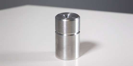
CNC turned parts
CNC turning refers to the creation of turned parts using the single-point tool. The cycle time calculation for the turning operation is no different than the milling operation. The length is also based on the formula:
L= Job length + Tool over Travels x Number of Passes + Tool approach length and Average RPM (N) = 1000*cutting speed/π*average diameter.
Let’s calculate the feed per revolution (f) & RPM (N) of the turning operation by taking the same example we did for the milling operation above.
Since the feed per tooth is the known variable, we calculate the feed per revolution (f) by multiplying the feed per tooth by the Number of teeth.
f= 0.1 * 30 = 3mm/revolution
N= revolution of the workpiece per minute (rpm)
= 1000* cutting speed (V)/π*Diameter (D)
= 1000*30/ 3.14* 200
= 47.77 rpm
The total production cycle time will be (T) = L* number of passes/f*N = 224*5/ (3*47.77) = 7.81 minutes
3. CNC Drilling
CNC drilling involves the creation of round holes in the stationary workpiece with a rotating tool. The cycle time of drilling refers to the time to create one or more holes, which depends on the machining tool, feed rate, and Spindle speed.
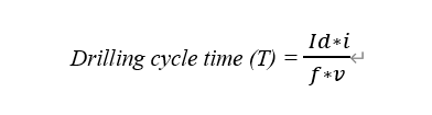
Where,
i= Number of holes
Id= Drilling depth (mm)
v= Spindle speed (/min)
f= Feed rate (mm/ rev)
Additional Approach of Calculation
There is another straightforward way of estimating the production cycle time in CNC machining. It can be calculated by dividing the time invested by the total number of parts or products produced (Verma, 2022).
Cycle Time (T) =Total time/number of produced parts or products
For Example, if a CNC machining set-up made 12 identical pieces in one hour, the cycle time for one part is 5 minutes.
Cycle time = 1 hour/ 12 parts = 60 minutes/ 12 parts = 5 minutes/ part
Reducing the Cycle Time
As the production cycle time is associated with the lead time and overall cost of CNC machining projects, it requires reducing the cycle time to optimize the overall cost of parts and end products to compete in the market (A. Vetrivel, 2018). Even when the CNC machining process has reached a state of stability, there may still be some factors that influence the cycle time. Therefore, controlling the Variability of a CNC machining operation is essential for speeding up the process.
While it is true that cutting cycle times lowers costs and lead times, there may be some situations where pushing cycle times is not reasonable due to equipment and operational constraints. In addition, lowering the cycle time below the undesirable limit also affects the functionality of parts. Let’s take a closer look at a few sensible suggestions for reducing the production cycle time.
1. Optimization of work-shop layout
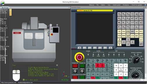
Machine layout simulation on a computer
The complicated layout of CNC machining contributes to the machining time because of unnecessary waiting or transit times. If the production cells are close, they will reduce the cycle time and make it easy to transition from one operation to another. Even a few seconds can shorten production times and boost machining productivity.
Therefore, you need to fix the layout according to the available space, raw materials condition, and the machining operations involved. In addition, there is an option for computer simulation to find the best possible layout, which minimizes production time by improving workflow.
2. Experienced operators
The productivity of CNC machining also depends on the skill of the operator. Expert operators can easily tackle the problems that arise during operation and will look for continuous improvement processes. Using skillful human resources in production will contribute to the lowering of cycle time.
Therefore, minimizing cycle time in any CNC machining project requires experienced operators with analytical abilities.
3. Optimization of 3D model
CNC machining can create complex geometries with a high degree of dimensional accuracy. However, the complexity increases the cycle time. If the designer creates a design simple as possible without disturbing the required features and functionality, the time will be reduced significantly. Complex design requires a complicated and frequent tool-set up to complete the job.
So, it is best to remove unnecessary complexity from the design and fix the best machining sequence for a shorter cycle time. Additionally, we collaborate closely with the developers to fix the ideal design to achieve the quickest production cycle time.
Related: Technical Drawing: Its Significance in Manufacturing
4. Production automation
The automated process is always more effective and quicker than manual effort. You can eliminate as much human work as feasible. Cycle time reduction is possible using high-speed CNC machines and advanced cam software such as solid CAM (A. Vetrivel, 2018)
Automation processes are more predictable and aid in obtaining correct cycle times with continuous improvement. When you automate the manufacturing process, the machinery remains stationary and optimizes the cycle time of each CNC machining operation. However, the automation process necessitates a significant initial investment, but it can be beneficial in the long run.
Related:
What is an industrial robot Types & Examples (2022)
5. Optimize the machinery performance
Excessive heating, vibration, and intrinsic restrictions are some constraints of CNC machines and other manufacturing machinery. These variables reduce production performance and contribute to a longer cycle time. To avoid these concerns, CNC machining manufacturers should prioritize frequent inspection, periodic maintenance, restocking, calibration, and other actions.
Technical tips for reducing the cycle time in CNC machine
There are several ways to reduce cycle time in CNC machines, including:
| No | Tips |
| 1 | Optimizing the cutting parameters: This includes selecting the correct cutting speed, feed rate, and depth of cut to maximize material removal while minimizing tool wear. |
| 2 | Reducing setup time: This can be done by using quick-change tooling, fixturing, and work-holding systems. |
| 3 | Improving machine efficiency: This can be done by regularly maintaining the machine and making sure it is running at peak performance. |
| 4 | Reducing non-cutting time: This can be done by automating as much of the process as possible, such as using robotic loading and unloading systems. |
| 5 | Reducing the number of operations: This can be done by using multi-function tools or combining multiple operations into one. |
| 6 | Improving the efficiency of the cutting path: This can be done by using the latest CAM software to generate efficient cutting paths that minimize unnecessary movement and optimize tool life. |
| 7 | Utilizing high-speed machining techniques: This can be done by using high-speed spindles, high-performance cutting tools, and high-speed cutting strategies. |
It is important to note that the specific approach to reducing cycle time will depend on the specific machine and application. An experienced CNC machinist or a process engineer can help you to identify and implement the best strategies for your specific needs.
What Are the Importance of Life Cycle Management?
Life Cycle Management (LCM) is a key strategy employed by manufacturing businesses worldwide to effectively manage the entire lifecycle of a product, from inception to disposal or recycling. When applied to CNC parts, LCM helps businesses maximize the value of their products while minimizing the environmental impact. This section will discuss why understanding and managing the lifecycle of CNC parts is crucial for businesses.
Here are the primary reasons:
- Cost Efficiency: By understanding the lifecycle of a part, companies can predict and plan for costs associated with each stage. This allows for accurate budgeting and potential cost savings.
- Quality Assurance: Managing the part’s lifecycle, especially during the manufacturing and maintenance stages, helps maintain the part’s quality over time.
- Sustainability: End-of-life strategies like recycling significantly reduce the environmental impact of the parts, leading to more sustainable manufacturing practices.
- Compliance: For industries with strict regulations, lifecycle management helps ensure compliance at every stage, from design to disposal.
Conclusion
The production cycle time can be estimated in CNC machining operations using a simple formula involving machining length, feed rate, machining speed, and other variables. It might be slightly changed based on the particular CNC operation, such as milling, turning, and drilling. Because cycle time is inextricably linked to any CNC machining project’s cost and lead time, optimizing cycle time adds to total cost reduction. There are various approaches to reducing cycle time, such as automation, frequent maintenance, trained operators, etc. Although cycle time can be computed using some machining variables, other factors affect the accurate result, such as human effort, vibration, excessive heat, and operator expertise.
Several factors must be considered to improve cycle time for cost reduction, and Prolean may be the perfect cooperating partner for your CNC machining project. We offer professional CNC machining services with 50+ material options for various tasks. Our manufacturing experts collaborate closely with developers to optimize cycle time for excellent results at a lesser cost. Please feel free to contact us; our sales engineer will get your quote within a few hours.
FAQ’s
What is the production cycle time in CNC machining?
Production cycle time in CNC machining refers to the total time required to complete a machined part, from the initial setup to the final inspection. It includes the time taken for tool changes, part loading and unloading, and actual machining time. Accurate cycle time estimation is crucial for cost estimation, production planning, and overall efficiency.
What is the importance of production cycle time in CNC machining?
The time required to complete one or more CNC machining tasks is referred to as the production cycle time. Since more time equals more cost, it is critical to lower the entire cost & lead time of parts or end-product.
What are the necessary variables to calculate the cycle time?
Cycle time is calculated using machining length, speed, feed rate, revolutions per minute, and other factors. However, the required input may differ from one machining operation to the next.
What is the CNC turning cycle time calculation formula?
The CNC turning cycle time calculation formula is:
Cycle Time = (Cutting Time + Tool Change Time + Rapid Movement Time) / Number of Parts
To calculate the cutting time, use the following formula:
Cutting Time = (Workpiece Length + Approach Length + Overtravel Length) / (Feed Rate x Spindle Speed)
Can I use Excel for CNC machining cycle time calculations?
Yes, you can create an Excel spreadsheet to perform CNC machining cycle time calculations. Input the required data, such as cutting speed, feed rate, depth of cut, and tool path length, and use appropriate formulas to calculate the cutting time, tool change time, and rapid movement time. Finally, sum up these values to obtain the total cycle time. please free to download Cycle Time Calculation Spreadsheet for your own project.
How can the production cycle time be reduced?
Optimization of 3D models, reduction of machining downtime, optimal machining layout, automation, expert operators, and regular machinery maintenance all contribute to lowering production cycle time.
Bibliography
- Vetrivel, A. A. (2018). Manufacturing Time and Cycle Time Reduction in CNC Machine Shop. International Journal of Research in Engineering, Science and Management (IJRESM), 1-2.
- Unit 5 Machining Time Calculation. (2012). In Process Planning & Cost Estimation (pp. 2-3). srividyaengg.
- Verma, E. (2022). Understanding TAKT Time and Cycle Time vs. Lead Time.com.


The seven tips you included for reducing the production cycle time was amazing. I am also an CNC machining operator , Here I would like to add something
8 . Adopting Predictive Maintenance: Incorporate a system that anticipates when components or parts are likely to fail based on usage and wear patterns. By replacing or maintaining them just before they fail, downtime can be minimized.
9 Training Machine Operators: you can continuously train machine operators to keep them updated with the latest machining techniques, best practices, and ways to troubleshoot common problems. Well-trained operators can often identify and resolve issues before they escalate.
We have been implying these strategies provide a comprehensive approach to decreasing CNC machining cycle time, leading to increased productivity and profitability.
Thank you ! and expecting the similar article in future!
Of course, Adopting Predictive & schedule Maintenance are the key to optimize the production cycle time for each CNC machining operation.
Excellent article on Production Cycle Time in CNC Machining. I know how Production Cycle Time affects the cost-effectiveness of machined parts.
Indeed production cycle time is key when it comes to cost-effective production in CNC machining with out sacrificing the precision.
you must have done a lot research for this article. I am trying to build own Excel sheet for CNC machining cycle time calculations, I would appreciate if you published further article on this topic.
Thanks Takumi ! We are trying to share our expertise to guide you for CNC and other manufacturing services!