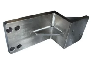
Sheet Metal Bending Service
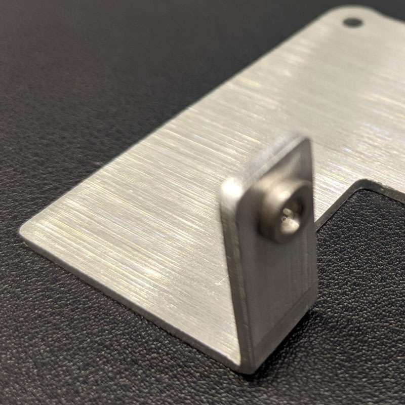
Craft precise angles with Prolean’s sheet metal bending services, specializing in metal bending tailored to your specific needs. Each final component or product undergoes rigorous quality control to ensure it meets the exact specifications and standards required.
- 1-135° bends
- Standard accuracy ±1°
- Aluminum, stainless steel, copper, titanium, etc
- ISO 9001:2015 certified quality control
- Lead time as fast as two days

All uploads are secure and confidential.
Our Amazing Clients

Try Prolean Now!
What is Sheet Metal Bending?
")
Sheet metal bending alters the geometry of sheet metals by applying force to achieve a particular shape. This process can involve a single bend or multiple bends, depending on the desired final shape. The minimum thickness of a metal sheet that can be bent is up to 127 mm, though this depends on the material type and sheet thickness.
As a general rule, bend radii should be equal to or greater than the thickness of the sheet metal. The bending technique, also referred to as forming or press braking, involves using a press brake machine or a die-punch system to create the bends.
")
Why Choose Prolean’s Sheet Metal Bending Service?
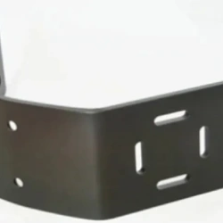
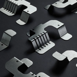
We can be your reliable manufacturing partner for any kind of metal bending parts & products. The complex bending features with precision, a wide range of material options, and custom solutions are key advantages from our side.
- Consistent, accurate custom bending for automotive, aerospace, medical, industrial, and agricultural applications. We streamline prototyping to mass production, turning your designs into reality.
- We adhere to strict and professional standards, from material selection to processing production and quality inspection.
- Regular communication and support throughout the project. Get a perfect experience for metal bending product manufacturing.
- Cost-effective yet precise bending parts & products.
- Fast delivery time, with the quickest delivery within two days.
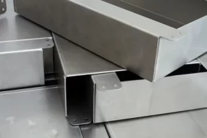
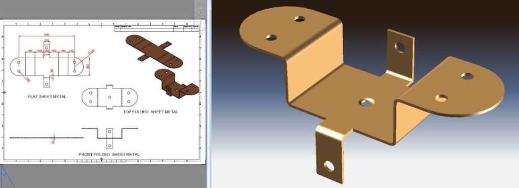
Our Sheet Metal Bending Capabilities
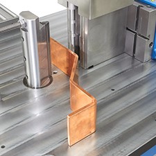
Our Advanced CNC bending equipment and qualified engineers work together to execute Air bending, V Bending, Rotatory bending, Folding, Coining, and several other bending processes.
Process Capabilities
Our sheet metal factory offers both manual & automated bending processes with compatible tooling, tailored to your needs & budget.
1. Manual Bending
Manual bending methods suit small-scale productions, with custom parts crafted by skilled operators.
- Press Brake Bending
- Roll Bending
- Air Bending
- Bottoming
- Coining
2. Automated Bending
We provide CNC and robotic bending for precise, repeatable results ideal for complex designs and large-scale production. Prolean’s automated bending equipments are:
- CNC Press Brakes
- CNC Roller Benders
- Robotic Bending Machines
Specific Capabilities
Features |
Info |
| Bend angle | ± 1 ° |
| Bend Variations | 0° to 180° |
| Sheet Thickness | 0.1mm-10mm |
| Part size limit | 6000mm*2400mm |
| Bend length | 2400mm |
| Bend to Edge | ±0.010″ 0.254mm |
| Bend to Hole | ±0.2 mm |
| General Tolerances | Metals: ISO 2768-c |
| Metal Folding Capacity | Up to 1000tons |
Try Prolean Now!
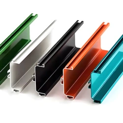
Materials for Sheet Metal Bending
Aluminum CNC Bending
Aluminum is a superior metal in terms of strength-to-weight ratio. It offers High Machinability, ductility, and thermal & electrical conductivity. Parts with aluminum also become highly resistant to corrosion.
Subtypes: 5052, 5083, 6061, 6082
Brass Bending Part
Golden shiny color, low friction, excellent Machinability, and high electrical & thermal conductivity. Brass can be easily machined and the best choice for low-friction applications.
Subtypes: C360, H59, H62
Copper Sheet Bending
It offers good strength and hardness, excellent corrosion resistance, and superior heat and thermal conductivity. It also has a very appealing aesthetic.
Subtypes: 101, C110
Steel Sheet Metal Bending
High mechanical strength, toughness, resistance to wear and fatigue, and sturdiness. In addition to carbon, other alloying elements can be added depending on the needed mechanical and physical qualities.
Subtypes: 1018, SPCC

Stainless Steel Sheet
High mechanical strength, Thermal, Wear, and Corrosion resistance. Stainless steel is low-cost and can be machined easily. Parts made from Stainless steel are durable and do not lose that strength over time.
Subtypes: 301, 304, 316
Carbon Steel Sheet Bending
Carbon steel is a high-strength iron alloy with excellent hardness and ductility. It is suitable for high-impact bending parts. Meanwhile, the coating or polishing can be done to increase its corrosion resistance.
Subtypes: 1008, 1020, 1045, 4130, 4340.
 Titanium Sheet Bending
Titanium is a strong yet lightweight material. It offers a high strength-to-weight ratio, corrosion resistance, exceptional hardness, biocompatibility, and good ductility.
Subtypes: Titanium Ti-6Al-4V, Ti-3Al-2.5V, and Ti-0.3Mo-0.8Ni.
Finishing Options For Sheet Metal Bending
We provide various surface finish options for your sheet metal project. If your required surface treatment is not listed below, feel free to contact us for more options.

As the machined or deburring
The machined or deburring finish is the standard finish where unwanted attach chips are removed with deburring tools, and sharp edges are chamfered to smooth the surface (3.2 μm).

Bead Blasted
Bead blasting produces a matte texture, removing all the marks of machining tools. It applies to ABS, Aluminum, Brass, Stainless Steel, and Steel parts.
Anodizing
Anodizing involves adding an aluminum oxide coating to aluminum and its alloys. The layers, which come in various colors, increase strength and shield the surface from corrosion.
Powder coating
Powder coating is the electrostatically applying of dry powder to the surface. It produces a thin layer providing excellent resistance to wear, corrosion, and abrasion.

Polishing
Physical rubbing of a metal surface to create a shiny surface is called a polishing surface finish. It increases the reflectivity and does not affect the dimensional stability of parts.
Brushing
Brushing is achieved by applying an abrasive brush to the metal surface, which produces a unidirectional satin finish. And it is not recommended for highly corrosive materials.
Smooth machining
Smooth machining is done by controlling the machining process, such as feed rate & cutting speed. It minimizes the tool marks and risk of corrosion.
How to Order Parts?
Get a free quote from a real engineer; once we receive your design, our engineer will review it and send you a quote as fast as one hour.

Get A Quote Immediately
Upload your design or email our engineer directly and get your quotes as fast as one hour.

Start Production
Your parts will be made once your orders are confirmed. Besides, you will get real-time order updates of the production status from our order tracking system.

Receive Your Part
After all parts pass QC inspection, they will be well packed from transportation accidents. Then, your custom parts are delivered straight to your doorstep.
Sheet Metal Bending Tolerances
- • If the length of the worksheet is less than 300mm
- • If the length of the worksheet is more than 300mm
| Description | Tolerance (MM) | Tolerance (Inch) |
| Hole to hole | ±0.10MM | ±0.0039 inch |
| Hole to Bend | ±0.20MM | ±0.0079 inch |
| Hole to edge | ±0.10MM | ±0.0039 inch |
| Edge to edge | ±0.15MM | ±0.0059 inch |
| Edge to Bend | ±0.20MM | ±0.0079 inch |
| Bend to Bend | ±0.25MM | ±0.0098 inch |
| Additional Bend Tolerance | ±0.25MM | ±0.0098 inch |
| Description | Tolerance (MM) | Tolerance (Inch) |
| Hole to hole | ±0.10MM | ±0.0039 inch |
| Hole to Bend | ±0.30MM | ±0.0118 inch |
| Hole to edge | ±0.15MM | ±0.0059 inch |
| Edge to edge | ±0.20MM | ±0.0079 inch |
| Edge to Bend | ±0.30MM | ±0.0118 inch |
| Bend to Bend | ±0.35MM | ±0.0138 inch |
3 Ways to Ensure Perfection
Standards
Metals: ISO-2768 fH (fine)
Plastics: ISO-2768 mK (medium)
Metric threads tolerances: ISO 965-1 standard UN Threads Tolerances: ASME B1.1-2003 standard
Knurling: ISO13444:2012 standard.
Our factory is ISO 9001:2015 certificated
Inspection and Protection
Constant visual inspection conditions
Quantification of cosmetic surface quality
Process requirements
Part cleaning and Protection
Quality Inspection Report
Inspection Confirmation
Dimensional confirmation
Appearance confirmation
Quality documentation
Sheet Metal Bending and Forming Guidelines
We suggest the following design rules to bend the metal parts within our tolerance range of precisely ± 0.25 mm in length and ±1 °.
![]() K-factor
K-factor
It is the ratio of the distance of the neutral axis to the sheet thickness. Maintain K-factor in a range of 0.25 to 0.5.
![]() Uniform Wall thickness
Uniform Wall thickness
Keep the wall thickness of bending parts consistent throughout the design. Prolean, we can use 8 mm with single sheet punching. If you have doable countersinks with counter-bores in design, that will need post-machining.
![]() Bending radius
Bending radius
The minimum inner bend radius should be at least equal to the thickness of the sheet.
![]() Distance between hole & bending position
Distance between hole & bending position
The minimum distance between the hole and the bending position should be 2.5 x sheet thickness (t).
![]() C-channel & U-channel
C-channel & U-channel
If your bending design contains a C or U-channel, each flange length needs half of the channel base. For example, if the base is 4″, then the flange on either side can be a maximum of 2″ long.
![]() Fillets
Fillets
Include fillet and chamfer filler in the sharp corners. The filler size should be Fillets with half the sheet thickness.
Notch & Tabs![]()
The minimum tab size can be equal to the thickness of the sheet, not exceeding five times the thickness (t). On the other hand, the minimum & maximum range of tab size is 2 to 5 times the sheet thickness.
Checklist
- The format of the file is according to the format we accept
- There is no text in your design. If any, they are in vector values as anchor points and curves.
- No intersecting or over-lapping lines in the design
- Designed are scaled as 1:1
- There are no void objects or open contours in the file.
Try Prolean Now!
CNC Plastic Applications
")
Automotive
Sheet metal bending is essential for manufacturing car parts like body panels, frames, and brackets. It ensures proper fit and structural integrity, making precision and durability crucial in vehicle production.
")
HVAC Systems
Sheet metal bending is crucial for forming air ducts and ventilation pipes in HVAC systems. It ensures proper airflow and installation for both standard and specialized systems.
")
Construction
Sheet metal bending is vital in construction for making roofing panels, sidings, and flashings. These components provide structural support and protect against the elements, enhancing building durability.
")
Electronics
Sheet metal bending is used to form computer cabinets, TV casings, and other consumer electronics. It ensures strong, protective casings with a modern, sleek appearance.
Technology Overview
Introduction
If you need any bending service for your project, Proleanis where you can get your parts created from Precise bending operation.
The ability to bend objects depends on their thickness, kind of material, and intended use. Accurate bending to meet your needs is difficult, butProlean’s makes it simple. Thanks to our cutting-edge machinery and qualified engineers, we will continuously fulfill your quality, service, and delivery standards.
What is Sheet Metal Bending?
Bending is the manufacturing process in which Sheet metal is transformed into desired shapes by applying pressure along an axis. The shape is created during the bending process through plastic deformation in the bending position.
The traditional bending machines struggle to obtain correct bending angles, and it may take a long time for them to turn at proper angles since they must undergo numerous Hits & Trial Steps. While CNC bending machines operate according to pre-programmed instructions and allow the setting of different bending angles following the desired bending positions, they are faster and more accurate.
CNC bending method produces exact dimensions according to the uploaded CAD file because this technique is more automated and accurate in bending sheet metal than traditional ones. The sheet is shaped using a hydraulic mechanism (Press brake) that the computer can fully control.
Advantages
- Complex shapes are possible, including triangles with bent corners and all types of curves up to entire circles.
- Less production time
- A high degree of accuracy on bending angle
- Less production time
- Cost-effective
- High Working efficiency
- Design flexibility
- Less post-processing
- Reduced number of parts
Types of Bending
In air bending, the outside edges of a die & punch tip are used to create the bend on sheet metal. Because it requires significantly less tonnage to bend than other forms of bending, it is the most popular among manufacturers. Additionally, air bending offers more flexibility in shape and bending radius.
Rotating cylinders with a V-Opening are used in rotary bending. It is used when a bending angle larger than 900is required. For pre-painted or damaged surfaces, it works best. The roll bending process is used for sheets and bars. The primary purpose of this process is to induce a curve shape bar into the straight plate.
Coning produces consistent bending over sheet metal workpiece like coins that are uniform in shape. It is a straightforward process in which sheet metal is stamped between the punch and die. With Coining, a small tolerance & a high degree of reproducibility can achieve. Additionally, the interior radius can be decreased to any desired level.
Folding, wiping, Joggling, and Elastomer are the other types of bending used in manufacturing.
Applications
CNC Bending is used in various industries to make several pieces of equipment and parts. Some of them include;
- Automotive components
- Pipes and tubes
- The exterior of aircraft and other parts
- Defense
- Hardware components
Sheet Metal Bending FAQs
What is the most suitable technique for bending sheet metal?
There is no best sheet metal bending method as all the methods have been designed to accomplish certain tasks to get desired outcomes. The ideal technique varies depending on the type of material, the thickness, and the final form that is desired. The choice of the right technique will to a greater extent depend on the end use and design requirement of the project.
How easy is It to bend sheet metal?
Working with sheet metal usually requires bending and this is not easy especially when the metal is thick such as steel. But once you know the correct techniques and are using the correct tools, it becomes a lot simpler. The bending process and tools used in the process will be easily comprehensible when it is broken down.
What are the Different Methods of Sheet Metal Bending?
Sheet metal bending can be done in several ways, and each of the methods is intended for a particular usage. Some of the most frequently applied techniques are Air Bending, Bottom Bending, Coining, Folding, Wiping, Rolling, Rotary Bending, Three Point Bending, and Joggling. All of them are useful in different ways and it is recommended for a project depending on the level of accuracy needed, the thickness of the material, and the type of design.
What is the difference between sheet metal bending and stamping?
Sheet metal bending is a process of bending the metal to the required angle or shape while sheet metal stamping uses a die to cut or shape the metal in the required shape. Bending changes the shape of the metal without having to cut or shave off some part of it while in stamping, there is always a cutting or reshaping by the use of a die and a punch.
What are common issues in sheet metal bending?
The most common bending issues include spring back, in which the bent metal returns to its original shape and cracking, which results from a tight bending radius or due to the brittleness of the material. All these problems can be solved when designing the bend and when choosing the right materials to use.
Related Blog
Aluminum Stamping: Complete Guide to Processes, Dies, and Parts
Aluminum stamping Modern manufacturing in many industries and aluminum stamping are intertwined. The process entails transforming thin sheets of aluminum metal into precise 3D parts of varying complexity, based on the design requirements. Whether you require stamped aluminum parts for automotive,...
A Comparative Guide on Metal Stamping and Forming
Metal stamping converts the flat sheets into the desired shape using various metal forming operations.
What is Copper Sheet Metal Fabrication? A Detailed Guide
Copper fabrication You can fabricate both pure and alloyed copper. Sheets of C101, C110, and other types of sheet metal are cut, punched, bent, and welded to create the desired shape. Copper sheet metal fabrication services are ideal for producing products that require thermal conductivity,...
Get Your Parts Made Today
All uploads are secure and confidential.