Technical Drawing
Technical Drawings bridge the gap between design and production. These ensure that parts are made accurately and function as intended.
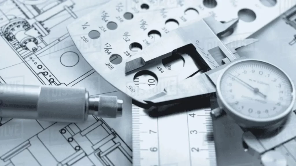
While CAD files provide digital models, technical drawings provide detailed specifications. They include information like material types, surface finishes, and tolerances. This additional data gives clarity and reduces errors during production.
Technical drawings are legal documents. They are part of contracts and protect designers and manufacturers. If discrepancies arise, these drawings provide a precise reference point for resolution.
A technical sketch or drawing encompasses several critical components: For example;
- Dimensions: These drawings indicate the size and scale of the part.
- Tolerances: These define acceptable variations in dimensions.
- Material Specifications: The material details to be used are given in these drawings.
- Surface Finish: These describe the texture or quality of the surface.
- Assembly Instructions: Guide the assembly process.
Historically, technical drawings were often prepared as 2D orthographic drawings. With advancements in technology, Computer-Aided Design (CAD) has become prevalent. However, conventional drawings remain relevant for their clarity and detail. Let’s get a detailed outlook on what a technical working drawing is and how to avoid common mistakes during its preparation.
History and Evolution of Technical Drawing
Evolution of Technical Drawings
Technical drawing follows strict global communication rules. You can use it to align teams on a project without confusion. Over time, this skill grew with the rise of modern engineering. Leonardo da Vinci started early practices with 2D sketches of machines. He used shadows, notes, and angles to show how parts work.
Later, Gaspar Monge introduced Descriptive Geometry. This is a method that defines technical drawing today. Alfredo Bensaude, a pioneer in Portugal, pushed students to learn by drawing, not just theory. You can’t ignore how this practice shaped today’s engineering programs. It’s still a core subject that teaches you how to think, plan, and build with precision.
Types of Technical Drawing
The following practical explanation details these technical drawing and design types
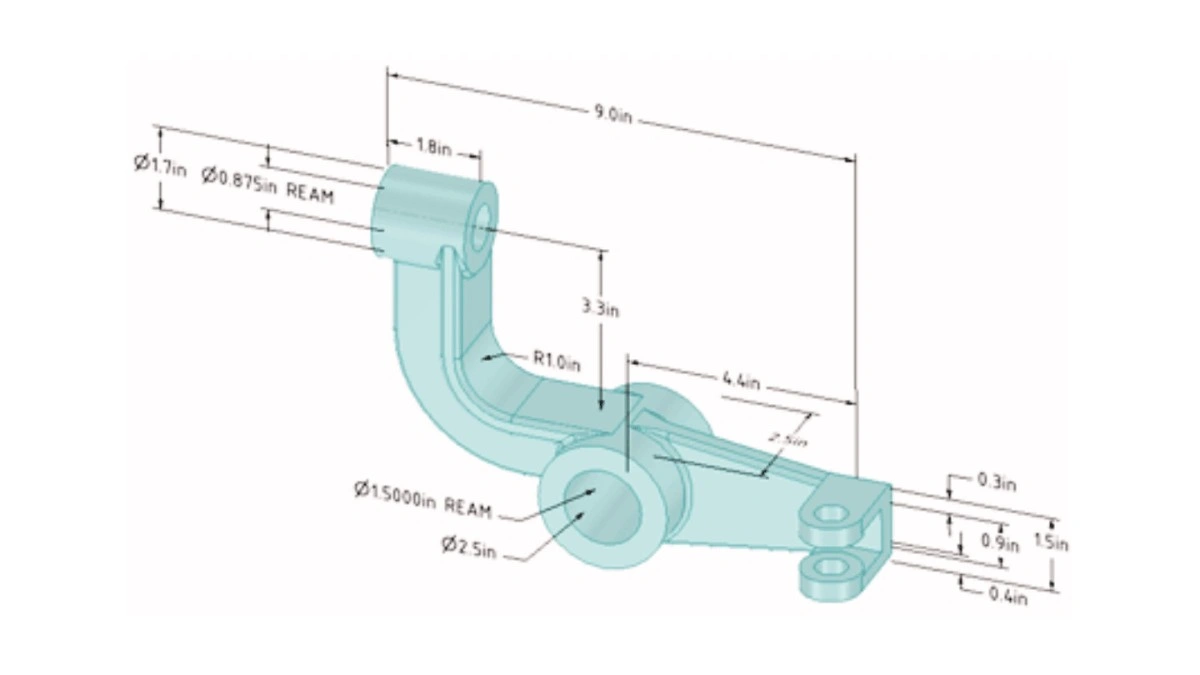
Engineering Drawings
Engineering Drawing
Anyone working in product design or machining must use engineering drawings. These drawings present precise part measurements, hole specifications, threading information, dimensional limits, and assembly component interactions.
The drawing you send to CNC machining or 3d printing services clearly defines all the necessary instructions without any doubt for the technician. Due to strict industry standards and precise manufacturing needs in automotive, robotics, aerospace, and industrial machinery, Manufacturer Series VI is preferred for technical drawings.
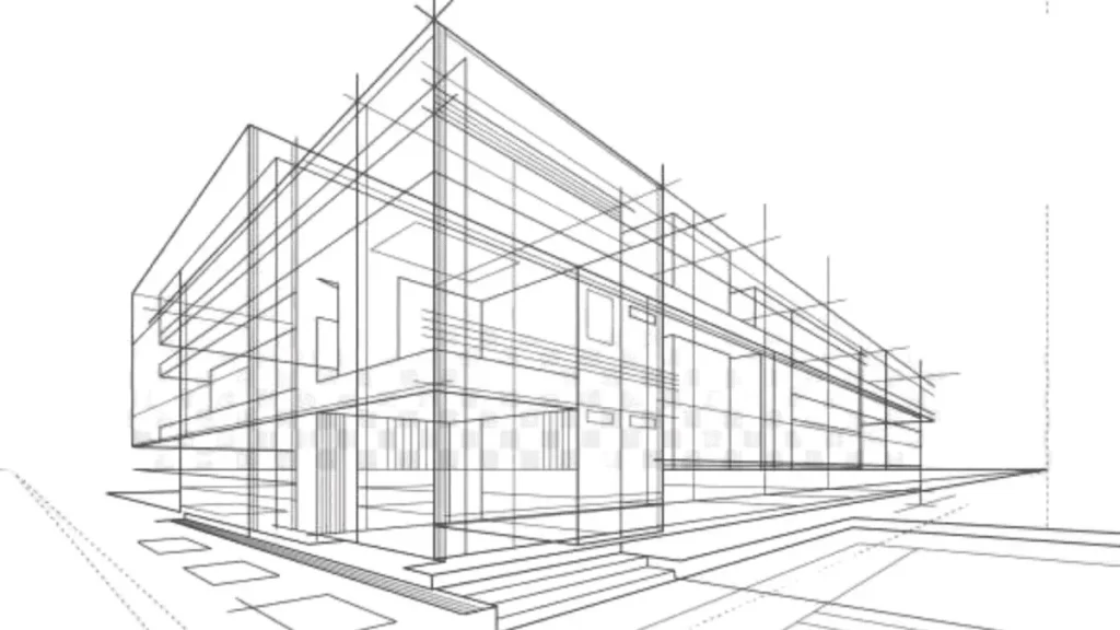
Architectural Drawings
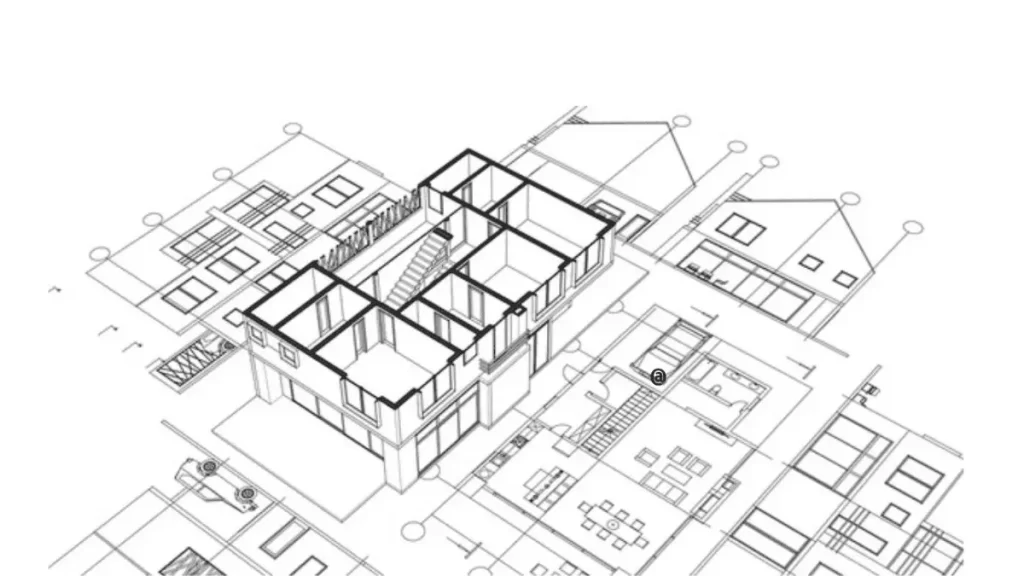
Architectural Drawing
Construction starts with architectural drawings, which function as the complete design documentation. These drawings serve as the reference for constructing residential spaces, business facilities, and production buildings. They present floor plans, roof layouts, cross-sections, and material specifications.
In this domain, the drawings help confirm that steel beams match concrete columns and stairway safety requirements are met. Civil engineers and construction workers use these drawings to prevent on-site mistakes that would result in significant expenses.
Electrical and Schematic Drawings
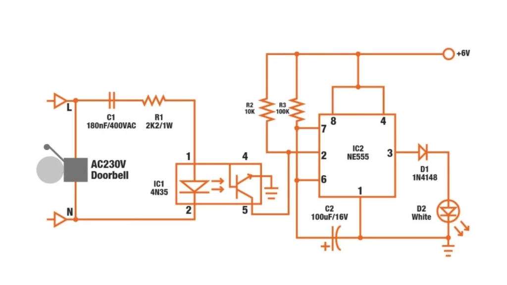
Electrical Wiring Drawing
The drawings serve as tools for building wiring and control panel assembly. The layout depicts how electrical sockets should be positioned alongside breaker positions and how cables must run within the system.
These schematic diagrams present complex systems through structured breakdowns, such as control circuit networks within manufacturing lines and HVAC systems for commercial buildings. Moreover, the drawings enable electricians and maintenance engineers to identify system problems and safely set up equipment so they do not damage the systems.
Specialized Industry Drawings
Construction Industrial Drawing
The drawings used in specialized industries, including aerospace, oil & gas operations, and precision tooling, require advanced technical specifications. Installing jet engine components depends on GD&T (Geometric Dimensioning and Tolerancing) standards for aerospace parts. The mold tool drawings used in injection molding define gate position and indicate cooling procedures and ejection system requirements. The drawings are specifically developed to fulfil essential safety standards, performance requirements and regulatory conditions.
Try Prolean Now!
Key Elements of a Technical Drawing
A technical drawing should include these principal components.
Views (Orthographic, Isometric)
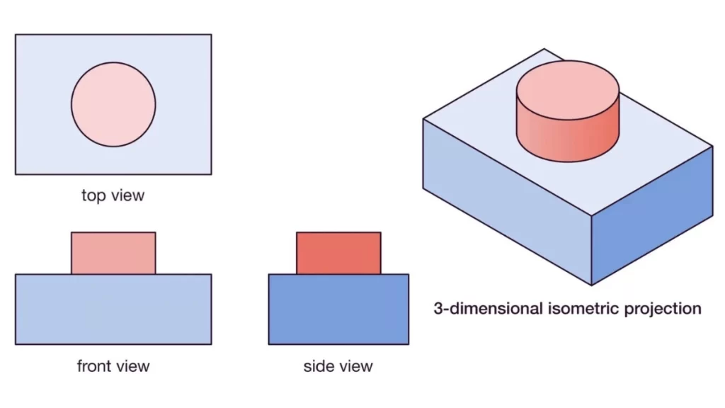
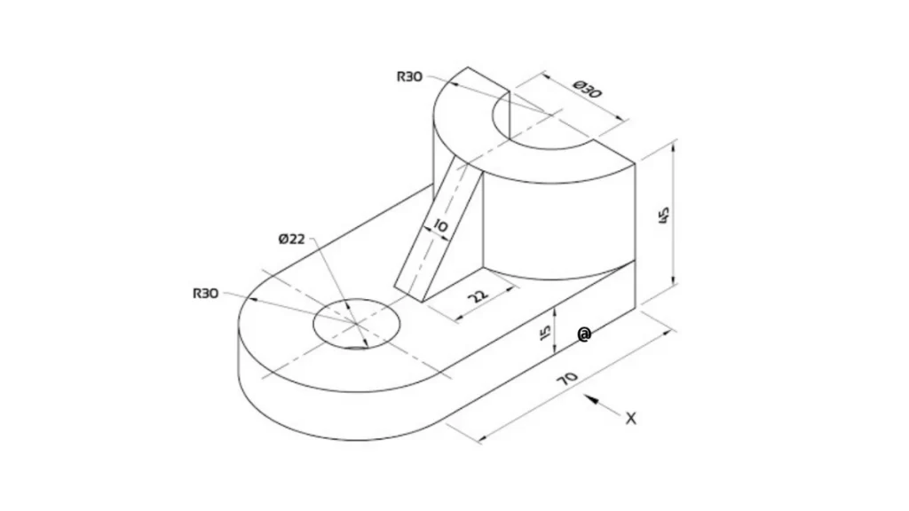
Isometric Drawing
The complete explanation of the part shape requires multiple views in your drawings. Each face of a part appears flat in orthographic views that include top view, front view, and side view to allow machinists to make accurate measurements. Each design team member and client gains better part visualization through isometric views. When used together, these views eliminate all potential misunderstandings in the workshop area.
Dimensions and Annotations
Creating dimension annotations
All technical drawings obtain their essence from dimensions. The drawings must display dimensions for the part length and width, every hole diameter, and specific spacing requirements. Line-based drawings are insufficient to represent annotations that require additional notes about chamfers, Metric threads, or weld spots. Including these details prevents the part from being misunderstood, leading to incorrect machining results.
Tolerances and Fits
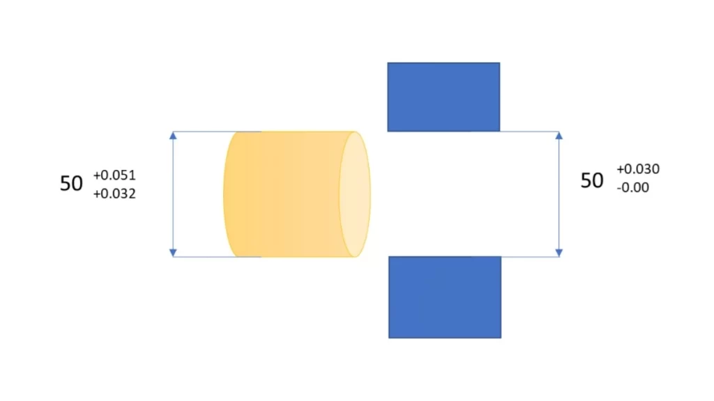
Interpretation of the system of fits on an engineering drawing
Tolerance specifications determine acceptable size range limits. Your dimensions should cover the complete part design from end to end to achieve proper fit and operational functionality after the machining process. A shaft and its bearing must have precise Press Fit Tolerance between their mating parts. However, when multiple dimensions interact, tolerance stacking can occur. Inadequate tolerances lead to part failure under stress conditions and prevent them from being assembled.
Materials and Surface Finishes
Material identification must be precise, as using the wrong material can lead to functional failure or non-compliance with specifications. Surface finishing treatments, including anodizing, powder coating, and polishing, determine the components’ cosmetic appearance and functional operation. Completing critical applications requires smooth finishes because rough surfaces can create unnecessary wear, but soft surfaces facilitate proper sealing and hygiene outcomes.
Sectional Views and Detail Views
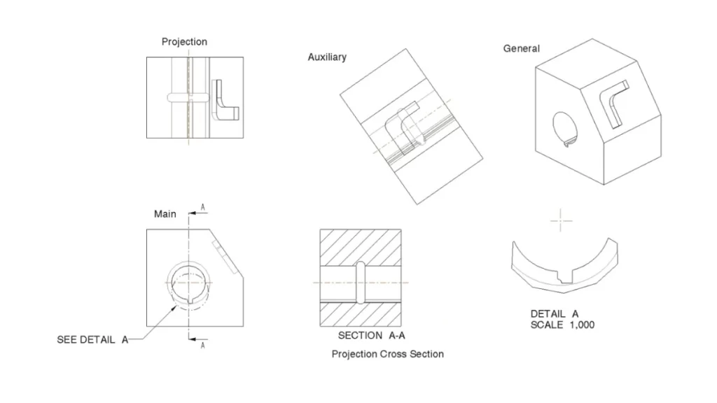
Sectional Views and Detail on Engineering Drawings
Manufacturers benefit from sectional views, which display interior part details through virtual cuts to check holes and internal ribs or wall thicknesses. Zoomed-in detail views focus on technical elements, including threads, grooves, and logo positions. The manufacturing process requires these visualization types to concentrate on specific accuracy-critical zones
How to Create the Perfect Technical Drawing: Step-by-Step Guide
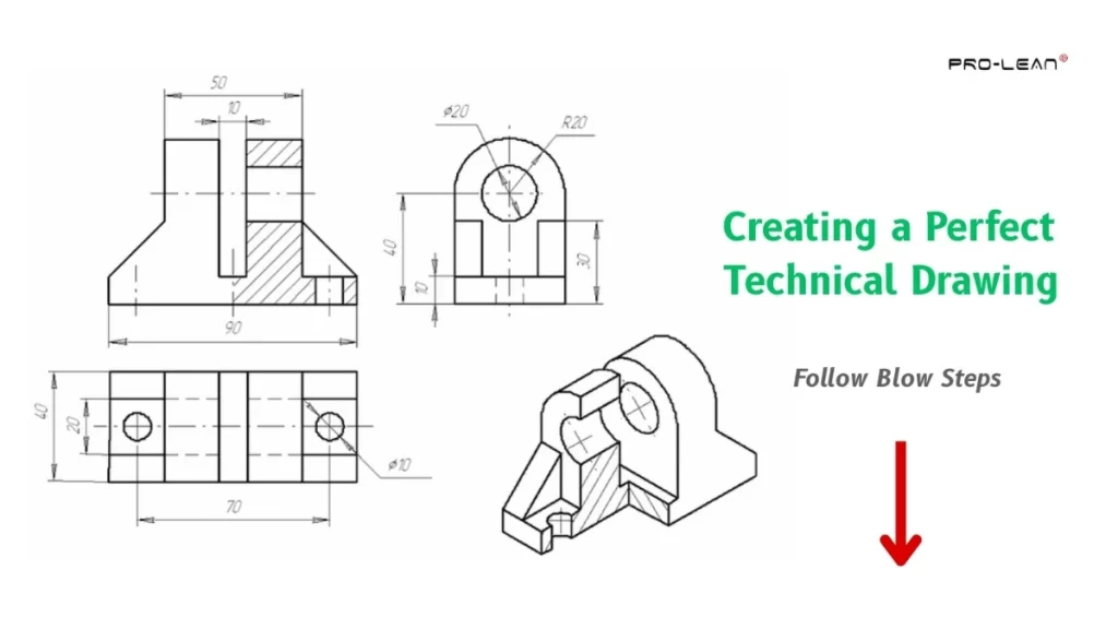
Steps to Create a Perfect Engineering Drawing
Creating high-quality technical drawings needs systematic work because it leads to precise and clear results. Follow this basic procedure to develop professional drawings which achieve effectiveness:
Use a Standard Template
Perform your drawing using a template that meets industry-standard norms like ASME or ISO. All technical drawings should start with a standardized title block showing company identification, approach authorisation, designer identities, drawing name, revision records, and graphical specifications.
Incorporate Coordinate Divisions and Notes
Complex drawings require coordinate divisions on the borders to serve as reference points. Keep a notes section where you maintain material specifications while adding required manufacturing standards and instructions.
Check Scale and Units
The drawing must fit within the paper dimensions, and the values must remain easy to read. International projects require metric units as their standard format, whereas U.S.-based projects should use imperial units. The practice of providing measurements twice proves secure for design purposes.
Specify Tolerances
You should set the specific tolerances by following the part’s technical needs and the manufacturing process’s technical capabilities. Use +/- 0.005” CNC machining tolerance for general dimensions. When tolerances impact production and costing, the drawings should display these specific tolerances.
Prepare Templates for Revisions
You should develop a revision tracking template that allows you to monitor modifications. The revision table must be included while you update the title block and add page numbers for user accessibility.
Align Views to Projection Standards
To avoid confusion, use the third-angle projection system for U.S.-based drawings and the first-angle projection for European or international standards.
Add an Isometric View
The part orientation becomes simpler because a 3d isometric view is included. The visual assistance requires no dimensional information since it functions as an aid for understanding.
Limit Hidden and Tangent Lines
Limit hidden lines to essential features, and include tangent lines that clarify geometry transitions. Hidden features must be included only if important, and their placement will be documented through exploded views or isometric drawings when necessary.
Ensure Clear Dimensions
Place dimensions outside the view area to prevent visual confusion. Without dimension replications, all critical measurements of arc threads and critical surfaces should be displayed clearly.
Detail Materials and Finishes
To avoid manufacturing complications, the documents should contain exact material descriptions (e.g., “304 stainless steel”) and all required finish specifications, such as anodizing and polishing.
Specify Thread Requirements
When creating specifications for threaded features, include complete details about thread form and dimensions, fit class, and depth specifications. When custom threads are specified, the thread profile must be shown in detail.
Apply Proper Tolerancing
The selection of appropriate CNC machining tolerances between bilateral, unilateral, and limit dimensions manages part variation. The standard, in most cases, involves bilateral tolerances, yet manufacturers must use unilateral or limit tolerances when fits are tight.
Implementation of Geometric Dimensioning and Tolerancing (GD&T)
In CNC precision machining, GD&T specifications should be applied to components that need precise geometric control. The standard symbols and datums enable the definition of form orientation, location and run-out tolerances. Reduce GD&T elements since excessive complexity will arise.
Clarify Surface Finishing Requirements
Explicit markings through symbols or notes should be used to define required surface finishes. Technical areas needing particular surface processes, such as anodizing and polishing, should be marked through cross-hatching and colored highlighting.
This process makes a detailed, accurate, professional technical drawing achievable, which leads to effective manufacturer communication and quality production results.
Common Mistakes and How to Avoid Them
Here are the common mistakes to avoid in technical drawings;
Missing Critical Dimensions
One major mistake occurs when essential dimensions disappear from the drawing. When vital information is not adequately transmitted, products become delayed during manufacturing.
Therefore, every drawing must possess all required measurements and be easily identifiable. All dimensions and critical tolerance specifications must be included so readers can avoid misunderstandings.
Overcomplicating Drawings
Overcomplicated Engineering Drawing
Drawing complexity should not exceed necessary detail thresholds since excessive complexity leads to confusion. Excessive lines, redundant information, and too many views will make drawings difficult for the reader to understand.
The drawing must contain straightforward and essential elements. After establishing their necessity, present sectional or detailed views exclusively to explain complex features.
Lack of Clarity in Tolerances or Materials
Production errors arise because of insufficient and absent tolerances and material specifications. Precise tolerances must always be provided, and the manufacturing process requirements must determine their appropriate values. You should give complete material specifications with exact grading standards to eliminate any confusion in specifications.
Ignoring Standard Conventions
Non-adherence to standard drawing conventions, including formats, projection types, and dimensioning, can lead to misinterpretation among manufacturers. Standards from ASME and ISO should be used because they establish a consistent format, which makes interpretation easier. Additionally, their use of conventions helps decrease the number of production mistakes.
Best Practices for Technical Drawings
Here are the best practices to follow for the best technical drawings;
Use Standard Symbols and Notation
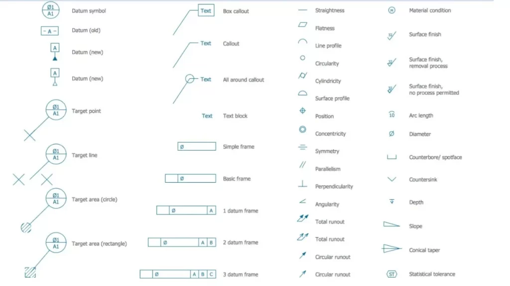
Standard Notations & Symbols Used In Technical Drawings
To prevent misunderstandings, all drawings should use standardized symbols and notation protocols, such as ISO or ASME. This method provides a shared understanding for all drawing participants, including engineers and manufacturers.
Maintain Consistency Across All Drawings
Your drawings need to use the same design style for all drawings. Each technical drawing must contain the same predefined title blocks, dimensioning scheme and file layout parameters. A standardized format allows anybody to read your drawings without difficulty.
Prioritize Clarity Over Artistic Representation
The main objective should be to achieve understandable communication instead of only decorative visual effects. Simple drawings should focus on essential data points such as dimensions and tolerances. They should exclude any design elements and extra details that will not add value to the drawings.
Always Consider the Manufacturing Process During Design
When you create the product’s drawings, consider production methods. Design your drawings for manufacturing by selecting appropriate materials, manufacturing tolerances, and easy manufacturability. Your design decisions at this stage minimize manufacturing mistakes and lower the required production revisions.
Key Features to Include in an Extrusion Technical Drawing
Technical drawings for plastic or aluminum extrusions need to contain these elements:
Stock Size
The necessary stock dimensions need to be included to use the appropriate material. Technical drawings include stock size information when possible, although production mistakes can be prevented without it. Due to this requirement, the correct material selection for custom extrusions becomes essential.
Grain Direction
Always specify grain direction for extruded or sheet metal parts where strength and formability depend. The direction of the grains of aluminium parts affects how they behave under stress. The provided information prevents potential problems that affect part longevity.
Exposed Surfaces
Mark all surfaces which need extra work in the manufacturing process. The surfaces that become visible must have particular finishing requirements and specific treatments. Marking allows users to avoid misunderstandings and ensures that appearance and operational requirements are fulfilled.
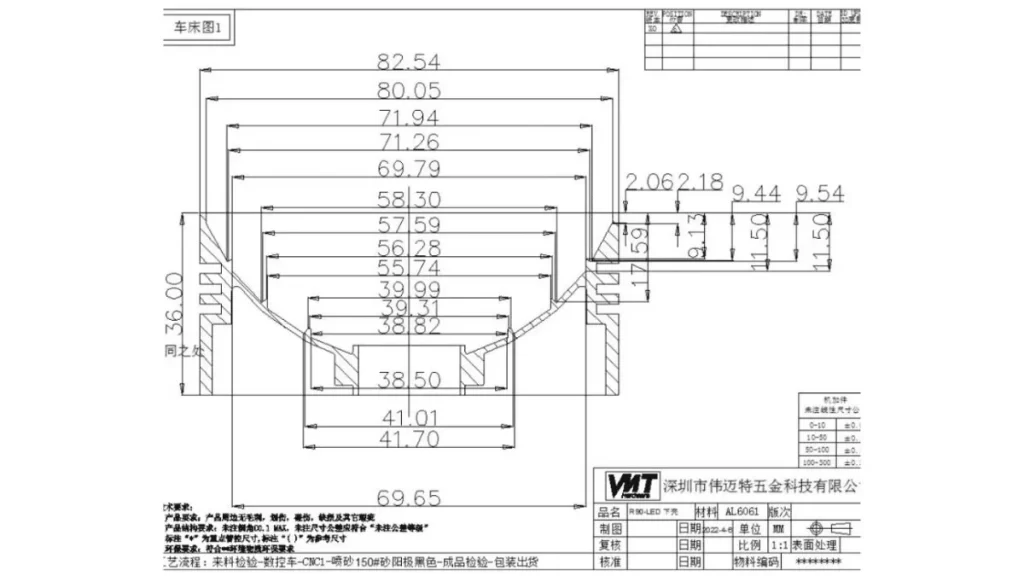
Hole Callouts
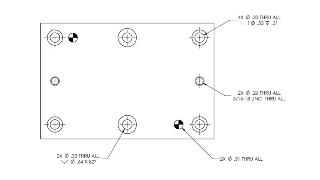
Hole Callouts
Detail views should show holes and their complete specifications. Hole callouts should include dimensions, positions, diameters, depths, tolerances, and thread specifications where applicable. The hole callouts in a drawing system guarantee proper assembly fit of extruded parts.
Summary
Technical Drawings are the backbone of effective communication in engineering and manufacturing. They determine that every design detail, from dimensions to materials, is accurately conveyed. Moreover, you can minimize the risk of errors and costly delays during production. Different technical drawings, such as engineering, architectural, and schematic drawings, each serve specific purposes and require attention to detail. Key elements like views, dimensions, tolerances, and materials are critical to creating clear and functional drawings.
If you need professional machining services, Proleantech is here to provide expert guidance and precision CNC machining services. With our expertise, you can be confident that your designs will be translated into accurate, high-quality products as per your specifications. Our team can handle all kinds of drawings. We have cooperated with many customers from different countries and are familiar with the standards of various drawings.
FAQ’s
Q1: What is a technical drawing?
A technical drawing is a detailed, precise visual representation of an object or structure. It conveys dimensions, materials, and specifications used in manufacturing and construction.
Q2: What are the types of technical drawings?
A few common types include assembly drawings, part drawings, schematic diagrams, and exploded views. Each type serves a specific purpose, from showing how parts fit together to detailing internal components.
Q3: Is technical drawing the same as engineering drawing?
Engineering drawings are a subset of technical drawings. These are explicitly used in engineering applications. All engineering drawings are technical drawings, but not all are for engineering.
Q4: What is the difference between CAD and technical drawing?
CAD (Computer-Aided Design) is a digital tool for creating technical drawings. A technical drawing refers to the actual document made by hand or with CAD.
Q5: What are the rules for technical drawings?
Technical drawings must follow standardized guidelines, such as line types, dimensioning, and projection methods. These rules facilitate clear communication and consistency across industries and teams.
It’s hard to find knowledgeable people on this topic, but you sound like you know what you’re talking about! Thanks