“The G code in CNC programming dictates the tool movement according to the determined tool path, an essential component of CNC operation.”
Do you know how a CNC machine executes the machining operations for a machinable CAD Design? CNC programming is responsible for this, which is the upload of digital instructions to the CNC control panel.
Based on CAD design, computer software like CAM analyzes the optimal tool path and cutting movements. Then, it generates the instructions for the CNC machine in the CNC G code and M Code formats. Furthermore, the code can be edited according to the project specifications for optional results.
G-code controls the movement and positioning of the CNC machine. It means it specifies the geometric path, such as linear and circular interpolation, tool movements, and positioning. In this article, we will review what is g code in detail, including its importance in precise machining, g code list, and g code example.
What is G Code Programming?
The G code commands in the CNC machine are not like simple line instructions. Instead, these are the systematic and well-structured commands that the machine understands and executes the process accordingly. Subsequently, G codes specify motions (e.g., G00 for rapid positioning and G01 for linear cutting).
CNC G code
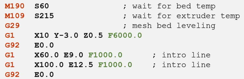
The G code file is typically generated into CAM software, followed by custom editing. Then, It is transferred to the CNC control panel via USB drives, network connections, or direct serial communication. The controller reads the G-code file, interprets the instructions, and executes the specified positioning and movements. For example, the G17 command in the file selects the XY plane for machining( positioning), and G00 X10 Y10 moves the spindle position (X-axis 10, Y-axis 10) from the reference panel for machining. Furthermore, the table below shows some examples of CNC G code command lines;
Table: Example of CNC G-code Commands
| Example | Description |
| G17 | Select XY plane |
| G21 | Set units to millimeters |
| G00 X10 Y20 | Rapid move to position (10, 20) |
| G01 X10 Y20 F100 | Linear move to (10, 20) at 100 mm/min |
| G02 X10 Y20 I5 J5 F100 | Clockwise arc to (10, 20) with center offset (5, 5) at 100 mm/min |
| G03 X10 Y20 I5 J5 F100 | Counterclockwise arc to (10, 20) with centre offset (5, 5) at 100 mm/min |
| G04 P1.0 | Dwell (pause) for 1 second |
These examples show how G code controls machining operations. But the final part quality also depends on machine capability and process control. See how CNC machining services outperform in precision and repeatability.
Try Prolean Now!
The G Code List
The letter “ G” stands for geometric, indicating that a G code list contains all the command syntax for CNC Machining. Each Command contains the letter G, filled by numbers 00 to 99.
Additionally, the list includes additional information for each line, such as category, function, and footnotes for complex commands.
Here is the G code list in simple form (Courtesy: CNC Cookbook)
| Code | Code Type | Description/ Function |
| G00 | Motion | Rapid Positioning |
| G01 | Motion | Move in a straight line at the last speed commanded by (F)rate |
| G02 | Motion | Clockwise circular arc at (F)rate |
| G03 | Motion | Counter-clockwise circular arc at (F) feed rate |
| G04 | Motion | Dwell: Stop for a specified time. |
| G05 | Motion | FADAL Non-Modal Rapids |
| G09 | Motion | Exact stop check |
| G10 | Compensation | Programmable parameter input |
| G15 | Coordinate | Turn Polar Coordinates OFF, return to Cartesian Coordinates |
| G16 | Coordinate | Turn Polar Coordinates ON |
| G17 | Coordinate | Select X-Y plane (Plane Selection) |
| G18 | Coordinate | Select X-Z plane (Plane Selection) |
| G19 | Coordinate | Select Y-Z plane (Plane Selection) |
| G20 | Coordinate | Program coordinates are inches |
| G21 | Coordinate | Program coordinates are mm |
| G27 | Motion | Reference point return check |
| G28 | Motion | Return to home position |
| G29 | Motion | Return from the reference position |
| G30 | Motion | Return to the 2nd, 3rd, and 4th reference point |
| G32 | Canned | Constant lead threading (like G01 synchronized with spindle) |
| G40 | Compensation | Tool cutter compensation off (radius comp.) |
| G41 | Compensation | Tool cutter compensation left (radius comp.) |
| G42 | Compensation | Tool cutter compensation right (radius comp.) |
| G43 | Compensation | Apply tool length compensation (plus) |
| G44 | Compensation | Apply tool length compensation (minus) |
| G49 | Compensation | Tool length compensation cancel |
| G50 | Compensation | Reset all scale factors to 1.0 |
| G51 | Compensation | Turn on scale factors |
| G52 | Coordinate | Local workshops for all coordinate systems |
| G53 | Coordinate | Machine coordinate system (cancel work offsets) |
| G54 | Coordinate | Work coordinate system (1st Workpiece) |
| G55 | Coordinate | Work coordinate system (2nd Workpiece) |
| G56 | Coordinate | Work coordinate system (3rd Workpiece) |
| G57 | Coordinate | Work coordinate system (4th Workpiece) |
| G58 | Coordinate | Work coordinate system (5th Workpiece) |
| G59 | Coordinate | Work coordinate system (6th Workpiece) |
| G61 | Other | Exact stop check mode |
| G62 | Other | Automatic corner override |
| G63 | Other | Tapping mode |
| G64 | Other | Best speed path |
| G65 | Other | A custom macro simple call |
| G68 | Coordinate | Coordinate System Rotation |
| G69 | Coordinate | Cancel Coordinate System Rotation |
| G73 | Canned | High-speed drilling cycle (small retract) |
| G74 | Canned | Left-hand tapping cycle |
| G76 | Canned | Fine boring cycle |
| G80 | Canned | Cancel canned cycle |
| G81 | Canned | Simple drilling cycle |
| G82 | Canned | Drilling cycle with dwell (counterboring) |
| G83 | Canned | Peck drilling cycle (full retract) |
| G84 | Canned | Tapping cycle |
| G85 | Canned | Boring cycle, no dwell, feed out |
| G86 | Canned | Boring cycle, spindle stop, rapid out |
| G87 | Canned | Back boring canned cycle |
| G88 | Canned | Boring canned cycle, spindle stop, manual out |
| G89 | Canned | Boring canned cycle, dwell, feed out |
| G90 | Coordinate | Absolute programming of XYZ (type B and C systems) |
| G90.1 | Coordinate | Absolute programming IJK (type B and C systems) |
| G91 | Coordinate | Incremental programming of XYZ (type B and C systems) |
| G91.1 | Coordinate | Incremental programming IJK (type B and C systems) |
| G92 | Coordinate | Offset coordinate system and save parameters |
| G92 (alternate) | Motion | Clamp of maximum spindle speed |
| G92.1 | Coordinate | Cancel offset and zero parameters |
| G92.2 | Coordinate | Cancel offset and retain parameters |
| G92.3 | Coordinate | Offset coordinate system with saved parameters |
| G93 | Motion | Inverse Time Feed Mode. For use with rotary axes |
| G94 | Motion | Units per minute feed mode. Units in inches or mm. |
| G95 | Motion | Units per revolution feed mode. Units in inches or mm. |
| G96 | Motion | Constant surface speed |
| G97 | Motion | Cancel constant surface speed |
| G98 | Canned | Return to initial Z plane after canned cycle |
| G99 | Canned | Return to initial R plane after canned cycle |
Although G codes define machine movement and operational logic, actual machining precision depends on how these commands are programmed in relation to tooling selection, feed rates, spindle speed, and machine rigidity.
Example of G Code Programming
To understand the complete form or how G code or the code file looks, let’s consider an example of G Code for drilling an 8 mm depth hole in the stainless workpiece.
- Workpiece size: 50 x 50 x 20 mm
- Hole Diameter: 4 mm
- Hole Depth: 8 mm
- Hole position: (2mm, 2mm) from centre
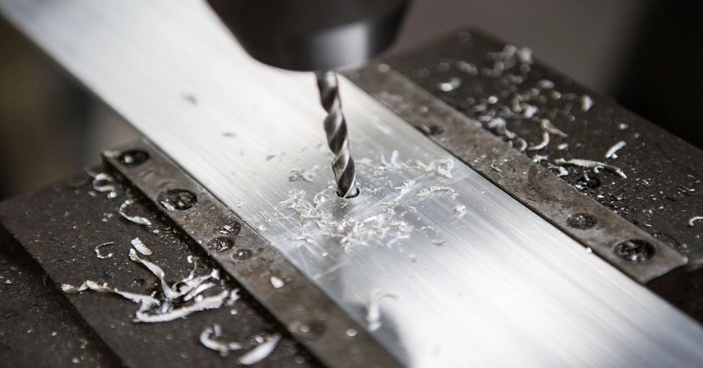
Steel workpiece drilling
Here is the G-code for this CNC drilling operation;
G21; Set units to millimeters
G17; Select XY plane
G90; Absolute positioning
G00 X0 Y0 ; Move to origin
G00 X27 Y27; Rapid move to hole position
G81 R2 Z-8 F100 ; Drilling cycle: Rapid to R2 (2 mm above workpiece), drill to Z-8 at 100 mm/min
G80; Cancel canned cycle
G00 Z10; Rapid move up to clear the part
M05; Spindle stop
M30; End of program
Moreover, you can check more CNC Programming Examples of G codes here. These codes (as well as M codes) are required for each operation you execute in a CNC machine.
What are the Differences Between CNC G codes and M Codes?
G codes and M Codes exist line by line in the same CNC programming file of particular machining operations; you can also see the two M code lines in the above example that have stopped the spindle and ended the program. A CNC M code starts with “M”, followed by numbers similar to G-codes. These are responsible for controlling auxiliary functions of the CNC machine, such as starting and stopping the spindle(M03 and M04), turning on/off the coolant(M08/M09), and ending the program(M30).
Furthermore, the table below differentiates CNC G and M codes.
Table CNC G code VS M Code
| Aspect | G-codes (Geometric Codes) | M-codes (Miscellaneous Codes) |
| Syntax | Starts with ‘G’ followed by a number | Starts with ‘M’ followed by a number |
| Examples | G00 (Rapid positioning), G01 (Linear interpolation) | M03 (Start spindle), M08 (Coolant on) |
| Purpose | Control the movements and operations | Control auxiliary functions |
| Functions | Positioning, cutting, interpolation | Spindle control, coolant control, program flow |
| Focus | Geometric and machining actions | Machine control and auxiliary actions |
| Usage Frequency | Used more frequently during machining operations | Used at specific points in the program for control actions |
Try Prolean Now!
Does G Code Programming Directly Affect the Quality of Machined Parts?
Just think, if the positioning of the spindle is 1 mm deviated from as required for the corresponding tool path, what will this error cause? Well, the result will be a complete failure of the desired part. This is a simple example; there are many other complications, especially in commands like offshore coordinates, local work shifts, coordinate system rotation, etc. Therefore, G-code programming directly affects the quality of machined parts. Proper G-code ensures precise tool movements, optimal feed rates, and correct cutting speeds. On the other hand, incorrect or poorly optimized G-codes can cause tool misalignment, excessive tool wear, and poor surface finish
At ProleanTech, You can leverage our engineers’ decade of experience in CNC programming to accurately transfer your CAD model (3D design) into a functional part or product. We use computer simulation to optimize the tool path and spindle movement so that we can maintain precision, consistency, and reliability in production. You can request a quote if you need CNC machining services. We are flexible in production volume, whether for a few prototypes or large-scale runs.
Read more: CNC Boring Program
Key Takeaways
- There are two functions of G code; execution of positioning movement of the spindle.
- A slight error in the G code caused tool misalignment and resulted in parts with defects.
- G Codes and M codes combined make a CNC program to execute the machining process. G-codes control movement and machining operations, while M-codes manage machine auxiliary functions.
- The frequency of CNC G code lines is higher in a CNC Program
- Optimized G-codes and advanced CNC machines are essential for precise machined components.
FAQs
What is G code?
G code, or Geometric code, is a programming language used to control CNC (Computer Numerical Control) machines, specifying movements, positions, and machining operations like cutting, drilling, milling, turning, etc.
How does CNC G code work?
CNC G code works by providing a set of instructions that dictate the movements and actions of a CNC machine. These instructions control the toolpath, speed, and operations.
Which tools create CNC G codes and M Codes?
CNC G and M codes are typically created using Computer-Aided Manufacturing (CAM) software like Mastercam, Fusion 360, and SolidWorks CAM.
Can I edit G-codes to optimize the machining operation?
Yes, you can edit G-codes manually to optimize machining operations. You can adjust speeds, feeds, and tool paths.

0 Comments