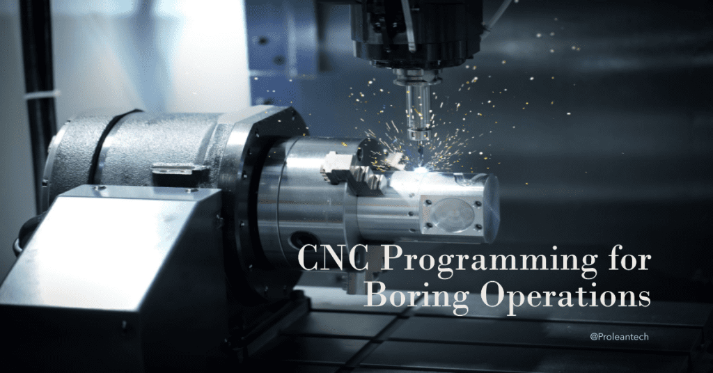
Programming for CNC boring operations is a critical skill for machinists, engineers, and technicians in the manufacturing industry. Understanding the concept of CNC programming used in boring operations can also help customers get superior results based on their requirements.
The right programming techniques can unlock the full potential of your CNC boring machines, leading to increased efficiency, accuracy, and cost savings. This comprehensive guide will cover the essential concepts of CNC programming for boring operations, discuss the most widely used programming languages and software, and provide valuable tips for optimizing your programming techniques.
The Basics of CNC Programming for Boring Operations
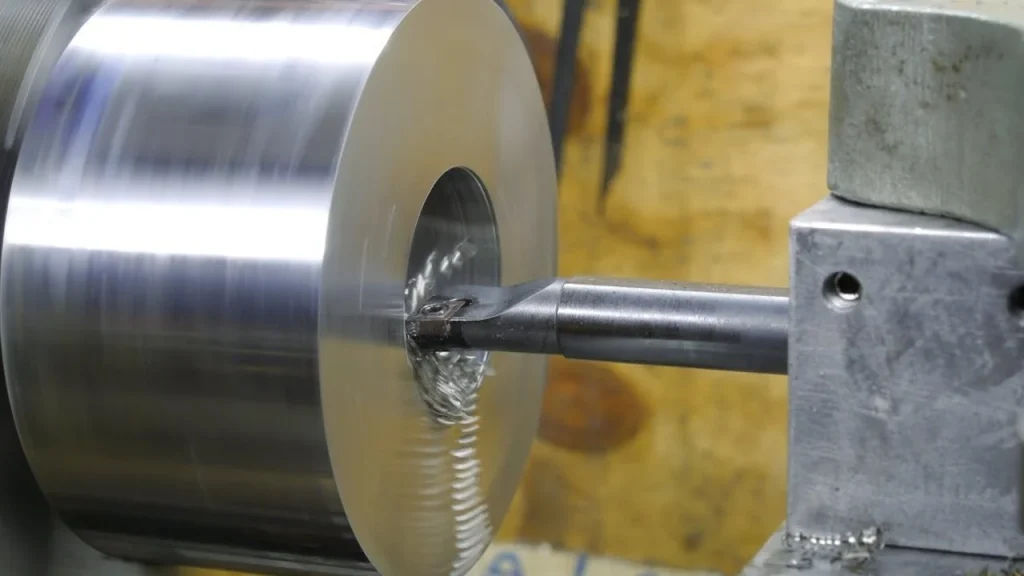
CNC boring is a machining process used to create precision holes, bores, or internal contours in various materials. It involves the use of specialized types of boring tools, such as boring bars and boring heads, mounted on a CNC machine. By accurately controlling the cutting tool’s path and depth, CNC boring can achieve tight tolerances, excellent surface finishes, and intricate internal geometries.
G-Code and M-Code: The Language of CNC Machines
G-code and M-code are the most commonly used programming languages for CNC machines. G-code (geometric code) contains instructions for controlling the movement of the cutting tool, while M-code (miscellaneous code) provides commands for auxiliary functions, such as coolant activation or spindle speed changes. A CNC program consists of a series of G-code and M-code commands that dictate the machine’s actions during the boring operation.
Essential Concepts in CNC Programming for Boring Operations
Some basic concepts in CNC programming include information on coordinate systems and work offsets, tool geometry and tool offsets, and feeds and speeds. Understanding these concepts is crucial for achieving precise and efficient machining results.
Coordinate Systems and Work Offsets
| Coordinate System | Description |
|---|---|
| Machine Coordinate System (MCS) | A fixed coordinate system that represents the CNC machine’s reference point, typically located at one of the machine’s extremities. |
| Work Coordinate System (WCS) | A user-defined coordinate system that represents the part’s reference point, allows the programmer to define the toolpath relative to the workpiece. |
| Work Offsets | Used to translate the WCS to different positions on the workpiece, enabling the machine to perform multiple operations without reprogramming. |
Tool Geometry and Tool Offsets
- Tool Offsets: Tool offsets are used to compensate for variations in tool geometry or tool wear, ensuring accurate and consistent cutting depths throughout the boring operation.
- Tool Geometry: The tool geometry refers to the dimensions and features of the cutting tool, including the tool diameter, length, and cutting edge angles.
Feeds and Speeds
- Feed Rate: The feed rate is the speed at which the cutting tool moves through the material and is typically measured in inches per minute (IPM) or millimeters per minute (mm/min).
- Spindle Speed: The spindle speed refers to the rotation speed of the cutting tool, measured in revolutions per minute (RPM). The optimal spindle speed depends on the boring material being machined and the tool geometry.
Try Prolean Now!
CNC Programming Software and Simulation Tools
There are different Software and Simulation Tools for CNC Boring operations. These tools help to visualize the process and predict the quality of the final result. Following are some typical tools used for programming and simulations in CNC boring operations.
| Tool | Description | Examples |
|---|---|---|
| CAM Software | Enables users to create toolpaths, simulate the machining process, and generate G-code and M-code commands | Mastercam, Autodesk Fusion 360, SolidCAM |
| CNC Simulation Tools | Allow programmers to visualize the machining process and identify potential issues before the actual cutting begins | VERICUT, NCSIMUL, CIMCO |
Tips for Optimizing CNC Programming for Boring Operations
Below are some tips to help you achieve superior results, including planning your toolpaths strategically, optimizing your feeds and speeds, utilizing canned cycles, implementing toolpath optimization techniques, and regularly updating and maintaining your CNC program library.
Plan Your Toolpaths Strategically
Careful planning of toolpaths can help minimize tool changes, reduce cycle times, and improve surface finishes. Consider using helical interpolation for large-diameter holes and roughing operations, and employ contour-parallel toolpaths for finishing passes to achieve smoother surfaces.
Optimize Feeds and Speeds
Ensure you select appropriate feeds and speeds based on the material, tool geometry, and desired surface finish. Choosing the right parameters can significantly impact tool life, cycle times, and machining quality.
Use Canned Cycles for Increased Efficiency
Canned cycles are pre-programmed machining sequences that simplify and streamline the CNC programming process for common operations, such as drilling, tapping, and boring. By utilizing canned cycles, programmers can reduce the number of G-code and M-code commands required, leading to shorter program lengths and faster setup times.
Implement Toolpath Optimization Techniques
Toolpath optimization techniques, such as trochoidal milling or adaptive clearing, can help reduce cutting forces, minimize tool wear, and improve machining efficiency. These methods involve the use of controlled, constant engagement angles and varying feed rates to optimize material removal rates and extend tool life.
Regularly Update and Maintain Your CNC Program Library
Maintaining an organized library of CNC programs for boring operations can help streamline future projects and reduce programming time. Regularly update your program library to include new tooling, materials, and machining strategies to ensure you’re always using the most efficient and effective methods.
Example of CNC programming for boring: 40mm dia. & 50mm depth
Here’s a simple example of CNC programming for a boring operation using G-code commands. This example assumes a 3-axis CNC machine and demonstrates how to create a hole with a diameter of 40mm and a depth of 50mm in a workpiece.
% (Start of the program)
O1000 (Program number)
G90 G80 G40 G17 (Absolute positioning, cancel canned cycles, cancel cutter compensation, and select the XY plane)
G21 (Set units to millimeters)
G28 G91 Z0 (Move the Z-axis to its machine reference point)
G90 (Switch back to absolute positioning)
M6 T1 (Tool change to boring bar, tool number 1)
G43 H1 (Activate tool length compensation for tool number 1)
S1200 M3 (Set spindle speed to 1200 RPM and start the spindle clockwise)
G54 (Select work offset 1)
G0 X20 Y20 (Rapid move to the starting position above the hole)
G99 (Set feed per revolution mode)
G98 (Set initial level return mode)
G83 X20 Y20 Z-50 R5 Q10 F100 (Canned cycle for peck drilling, with a 10mm peck depth and a feed rate of 100mm/min)
G80 (Cancel the canned cycle)
G0 Z50 (Move the Z-axis 50mm above the workpiece)
M5 (Stop the spindle)
G28 G91 Z0 (Move the Z-axis to its machine reference point)
G90 (Switch back to absolute positioning)
M30 (End of the program and rewind)
%
Please note that this is a basic example and should be adapted to your specific CNC machine, tooling, and workpiece requirements. It is crucial to consult your CNC machine’s manual and verify the compatibility of the G-code commands used in this example. Additionally, make sure to test the program in a safe environment, using proper simulation tools, before running it on an actual machine.
Conclusion
CNC programming for boring operations is an essential skill for those in the manufacturing industry, enabling the creation of precision holes and internal contours with exceptional accuracy and efficiency. By understanding the fundamental concepts of CNC programming, utilizing advanced software tools, and implementing optimization techniques, you can unlock the full potential of your CNC boring machines.
Partnering with a reliable company like Prolean’s Machining Service can provide expert guidance, state-of-the-art equipment, and unparalleled quality assurance, ensuring the success of your projects.
FAQs
What are G-code and M-code in CNC programming for boring operations?
G-code and M-code are programming languages used to control CNC machines. G-code contains instructions for the cutting tool’s movement, while M-code provides commands for auxiliary functions, such as coolant activation or spindle speed changes.
How do coordinate systems and work offsets play a role in CNC programming for boring operations?
Coordinate systems, such as the Machine Coordinate System (MCS) and Work Coordinate System (WCS), define reference points for the CNC machine and workpiece, respectively. Work offsets are used to translate the WCS to different positions on the workpiece, enabling the machine to perform multiple operations without reprogramming.
How can CAM software and CNC simulation tools improve CNC programming for boring operations?
CAM software streamlines the programming process by generating toolpaths, simulating the machining process, and creating G-code and M-code commands. CNC simulation tools help visualize the machining process, detect potential issues, and optimize toolpaths and machining parameters.

0 Comments