Mold flow analysis
Mold Flow Analysis (MFA) is a simulation process used in plastic injection molding processes. It helps manufacturers ensure the quality of products by identifying issues such as pressure differences, cooling time, and melt flow distribution. When such issues are identified before tooling, defects like warping, air traps, and short shots can be avoided in a timely and cost-effective manner.
From automotive to consumer products, and medical devices to packaging, many industries turn to professional mold flow analysis services to optimize production processes. To discover how these services can transform your manufacturing capabilities, read this review of the process. The post covers the definition, steps, and relevance of mold flow analysis.
What is Mold Flow Analysis?
Mold flow analysis (MFA) is the plastic flow simulation in a mold to identify issues such as uneven filling, weld lines, short shots, and air traps. It is a process that helps mold designers optimize part geometry, runners, and gates for enhanced moldability.
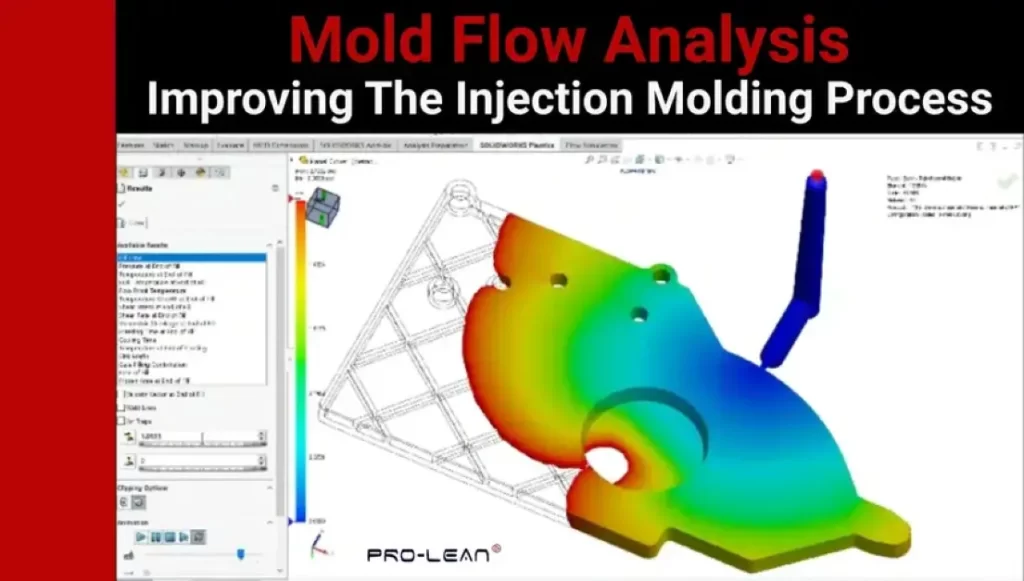
The injection molding simulation is done before the injection molding process, and simulation software is used. Design features appear in the simulation software as color maps. Some of the features that mold professionals tackle in these analyses are fiber orientation, shear stress, injection pressure, and fill pattern.
The Benefits of Performing a Mold Flow Analysis
The mold filling analysis in plastic injection molding offers benefits such as optimized design, reduced waste, and improved product quality.
- Design Optimization: Injection molding analysis allows designers to adjust the design where necessary for higher part feasibility
- Minimized Waste: Simulation helps identify manufacturing issues early, reducing waste of manufacturing time and materials.
- Improved Product Quality: Mold filling analysis ensures the right surface finish and dimensional precision. High-quality molded parts ensure elevated customer satisfaction.
The Limitations of Injection Molding Analysis
Key limitations of using injection molding simulation are cost, complexity, computational time, and accuracy challenges.
- Cost: Injection molding simulation software can be high-priced. Businesses in the initial plastic manufacturing stages can find this a major hurdle.
- Complexity: The meshing complexity is another potential challenge. The process can lead to inaccuracies in the case of poor generation.
- Computational Time: The complexity of the process is tied to its time-consuming nature. For processes requiring multiple simulations, the duration can be significant.
- Accuracy: Input data accuracy directly affects the analysis accuracy. There are many data points in an analysis. A minimal error in input data can significantly affect the accuracy of the results.
Six Key Reasons Engineers Rely on Mold Flow Analysis
First, it is important to note that injection molding analysis precedes tooling. Engineers use it for early defect detection, material selection optimization, faster product development cycle, parameter optimization, mold design improvement, and cost reduction.
Early Defect Detection – Helps identify weld lines, short shots, warpage, and other molding problems before tooling is implemented.
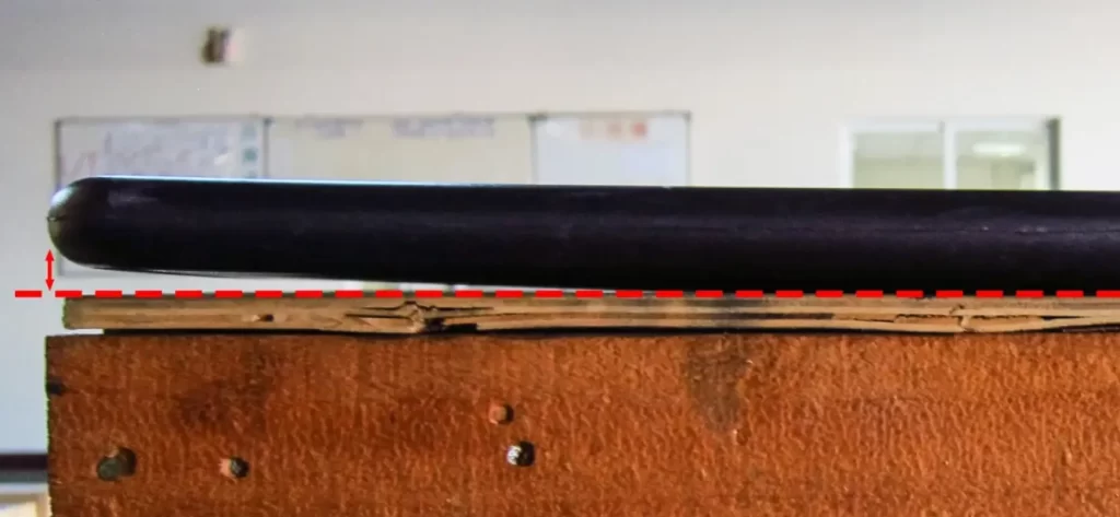
Warpage
Material Selection Optimization – Engineers use the simulation process to compare and select the ideal plastic for specific components/parts.
Faster Product Development Cycle – Engineers can perform design iterations and tooling modifications faster
Parameter Optimization – The process allows for optimization of cooling settings, injection pressure, and melt temperature
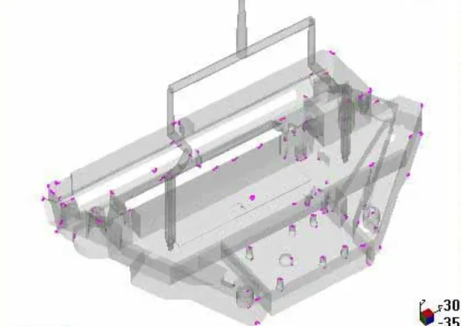
Mold Design Improvement – Mold flow analysis guides engineers in the placement of runners, gates, and cooling lines
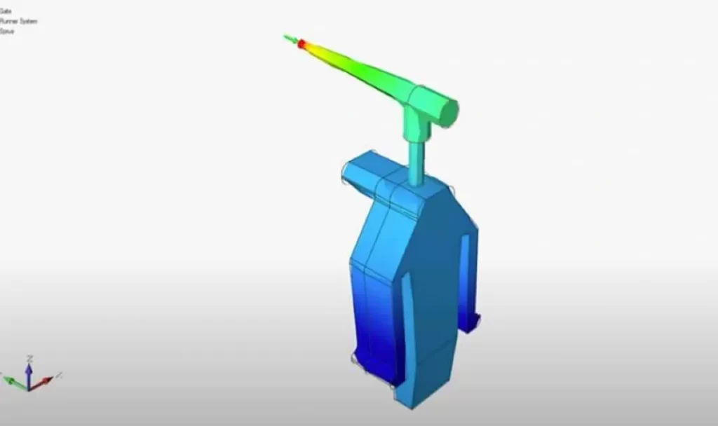
Gate location
Cost Reduction – Virtual design tests minimize costs associated with test runs
What Mold Flow Analysis Does for Your Bottom Line
By offering virtual solutions, injection molding analysis makes business sense in terms of shorter development cycles, reduced tooling costs, more successful first runs, and stronger client confidence.
- Shorter Development Cycles – Virtual test runs reduce the product development timeline
- Reduced Tooling Costs – Unnecessary expensive tooling modifications are avoided
- More Successful First Runs – The first production batch has a high chance of success, with issues solved early
- Stronger Client Confidence – There is documented proof of thorough part validation.
Common Problems Identified by Injection Molding Simulation
Experts use plastic injection simulation to identify sink marks, warping, weld lines, and air traps.
Sink Marks: Small, depressed marks on the surface of a plastic part. They are mostly formed around structural features or thicker sections. The main cause of sink marks is uneven cooling.
Sink marks
Warping: Warping is a molding defect defined by the deviation of a part from the designed shape after cooling and ejection. Moldflow analysis helps identify the issue in advance and apply the correct design strategies.
Weld Lines: Also called knit lines, weld lines are characterized by visible streaks and seams on a molded plastic part. These defects form at the meeting point of multiple flow fronts.
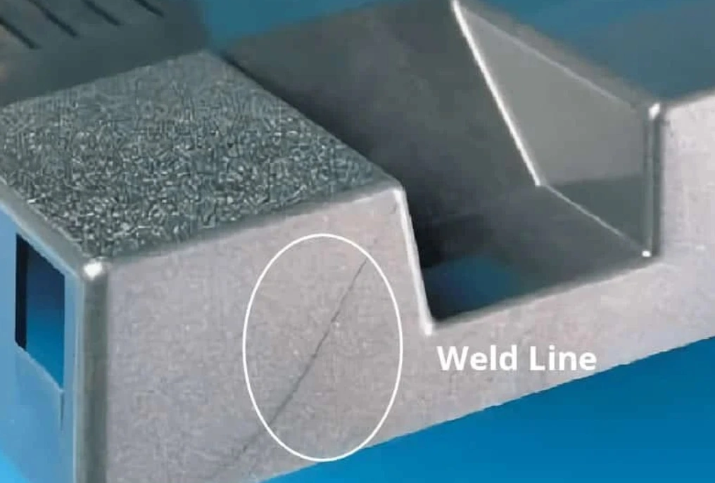
Weld line
Air Traps: Air traps form when converging flow fronts trap air. Moldflow analysis helps manufacturers prevent this issue through proper venting, gate location, and related strategies.
Air traps
The Mold Flow Analysis Process Steps
The mold flow analysis process comprises data preparation, mesh generation, material selection, simulation setup, simulation, and result analysis.
Step 1: Data Preparation
Data about the plastic material and mold parameters is gathered. Properties of the material include density, viscosity, and melting temperature. For the mold, the most important characteristics include the flow channels.
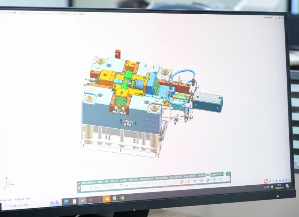
Step 2: Mesh Generation
Generating the mesh follows, forming the computational foundation of the analysis. Think of a mesh as a conversion of the CAD model into a system that the software can predict. The mesh can be 2D or 3D, based on the complexity of the mold. Mesh quality control is critical to ensure simulation accuracy.
Step 3: Material Selection
There are thousands of materials in the mold flow tool. The designer can select from thermosets and thermoplastics, among other materials. Plastic injection simulation also offers model options such as crystallization kinetics, viscosity, and PVT models.
Step 4: Simulation Setup
The next step is to set the simulation or process. The main elements here are boundary conditions and the simulation method. Engineers focus on filling settings, packing settings, and cooling settings.
Step 5: Simulation
During the simulation, dedicated software such as ANSYS, Moldflow Corp, or SolidWorks Plastics is in action. It helps observe the plastic flow.
Step 6: Result Analysis
The final step is to analyze the mold flow as presented in the software. Crucial information that can be derived from the software includes temperature, weld lines, and fill time.
The specific analyses are as outlined below:
- Filling Analysis: Mold filling analysis checks for incomplete cavity filling, air entrapment, and such problems. By identifying such issues, this analysis helps avoid mold short shots.
- Flow Analysis: This type of analysis focuses on flow patterns. Process engineers use the examination to detect weld lines on flow fronts that mix poorly.
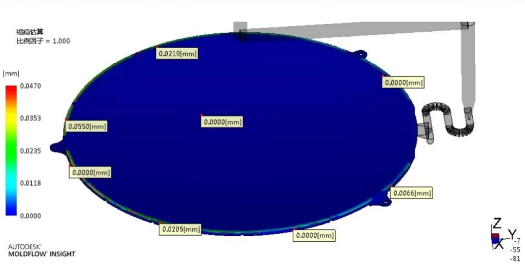
- Warpage Analysis: This is a reliable analysis for uneven internal shrinkage and uneven cooling. It guides in adjusting wall thickness and part geometry.
- Process Optimization: This entails using mold flow simulation results to improve various aspects of production runs, specifically holding pressure, injection pressure, packing pressure, and melt temperature.
Try Prolean Now!
Industrial Applications of Mold Flow Analysis
Professionals like ProleanTech use injection molding analysis for medical devices, packaging parts, consumer goods, and automotive parts.
Medical Devices: Moldflow analysis ensures medical devices are manufactured with the highest precision. The industry demands tight tolerances for complex parts. Many devices have thin walls, which can present manufacturing challenges. With this analysis, manufacturers can minimize risks and ensure cost-efficient manufacturing.
Packaging Parts: Caps and other thin-walled packaging items are typically manufactured using the moldflow analysis approach. It ensures structural integrity with minimal manufacturing material and thin profiles.
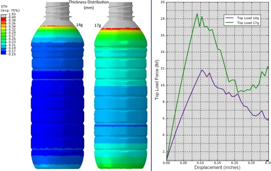
MFA for packaging
Consumer Goods: For everyday household items such as electronic enclosures and appliance covers, the analysis contributes to quality surface finish and dimensional stability. Manufacturers use the technology to prevent manufacturing defects that can affect user experience and product performance.
Automotive Parts: Air intake manifolds, dashboard parts, bumper covers, and many other automotive components require warpage analysis, mold-filling analysis, and other analyses during manufacturing. Their complex geometries and different plastic materials mean no single processing characteristic for every part. With the analysis, manufacturers can predict production properties, from shrinkage to warpage, for specific parts.
Best Practices in Mold Flow Analysis
The best practices in mold flow analysis concern data accuracy, mesh quality, model improvement, physical testing for validation, and partnering with experts.
- Ensure Data Accuracy: The information used for the plastic material should be accurate. This is one of the ways to ensure that the simulation results accurately reflect reality.
- Mesh Refinement: The mesh should be as refined as possible for accurate analysis. That’s especially critical in areas with significant flow variations.
- Update the Model: The results should be monitored continuously, and the model improved accordingly.
- Result Validation: Physical testing is recommended to validate the accuracy of the simulation results. Comparing the physical results with simulation results helps in identifying flaws.
- Partner With Experts: Finally, clients are urged to work alongside injection molding experts. Such partners have experience dealing with a range of manufacturing issues. With top expertise on their side, businesses are assured of consistently high-quality parts.
What is the Best Software for Mold Flow Analysis?
There are different software options for moldflow analysis, including ANSYS, Moldflow Corp, SolidWorks, and Moldex3D.

Autodesk Moldflow simulation software
Each has its strong selling points, but also potential limitations. So, the choice of which one to use depends on what the user is looking for.
This summary table provides some points to consider for each product.
|
Software Solution |
Properties |
|
ANSYS |
A standout product for thermal and structural analysis. Recommended if the analysis goes beyond the mold itself. |
|
Autodesk Moldflow |
Moldflow Corp software provides accurate predictions and has a broad material database |
|
SolidWorks |
Easy to use and offers smooth CAD integration. |
|
Moldex3D |
Ideal for complex geometry and detailed 3D simulations |
How To Read Mold Flow Analysis?
Reading the mold flow analysis is a systematic process covering fill time, pressure distribution, temperature distribution, and defects. It focuses on the flow, pressure, defects, and final shape of the part. To identify potential issues, including those related to injection molding tolerances, experts follow the following general steps.
- Step 1: Plot the fill time to identify color progression
- Step 2: Check the pressure distribution
- Step 3: Review the temperature results
- Step 4: Identify the defects
- Step 5: Interpret the analysis and take action
Try Prolean Now!
What’s In A Mold Flow Analysis Report?
The main sections to expect in a mold flow analysis report are basic data, material data, mesh diagnosis, filling analysis, gate location analysis, deflection & shrinkage, clamping force, pressure, and assessment & recommendations. This report is essential for designers and engineers because it records the simulation results. It provides valuable insights before actual production commences.
|
Element |
Description |
|
Basic data |
Project details, software type, clamping tonnage, maximum injection pressure, melt & mold temperature |
|
Material data |
Mold temperature, material density, melting temperature, and melt flow index |
|
Mesh diagnosis |
Evaluation of the mesh element thickness |
|
Filling analysis |
Fill time, weld lines, flow front temperature, air traps |
|
Gate location analysis |
Gate placement |
|
Deflection & shrinkage |
Part deflection and volumetric shrinkage |
|
Pressure and clamping force |
Clamping force and nozzle pressure distribution |
|
Assessment & recommendations |
Summarized findings – material, process, and tooling adjustments |
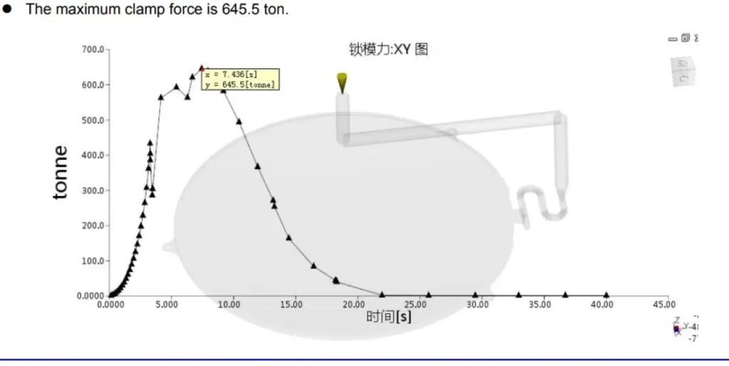
Clamp force data
Mold Flow Analysis vs. DFM
MFA and DFM focus on different manufacturing process elements. MFA is fundamentally designed for the injection molding process. DFM is a wider strategy that focuses on product design simplification.
Design for Manufacturability (DFM)
In other words, while MFA is a process-centric tool, DFM is a design tool for an overall cost-effective product.
Mold Flow Analysis Success Story
A few months ago, an automotive parts manufacturer approached our team, requiring injection molding housing components made of ABS plastic. The assembly fit had issues, which we established were caused by warpage and sink marks. The engineering team sprang into action to perform a mold flow analysis and pinpoint the root cause(s). The various analyses were;
- Material Comparison: This analysis recommended the use of glass-filled ABS grade instead of ordinary ABS
- Filling Analysis: It showed uneven mold cavity filling. The cause was poor gate placement.
- Warpage Analysis: It was established that non-uniform cooling was promoting dimensional inaccuracy.
- Process Optimization: This analysis recommended proper cooling line placement and accurate packing pressure.
Conclusion
Moldflow analysis is one of the biggest money and time savers in injection molding. Fundamentally, MFA is a simulation-centered process that predicts the flow, cooling, and solidification of molten plastic inside a mold before manufacturing begins.
From identifying air traps and weld lines to optimizing process parameters, the analysis helps engineers and other stakeholders make informed decisions about plastic injection molding. It ensures your plastic parts are produced efficiently, cost-effectively, and to standard.
At ProleanTech, we not only adhere to this technical requirement for analysis but also use the latest tools. We help businesses use simulation insights to improve the design and manufacturing of plastic parts. With this analysis capability, our injection molding services are designed to address challenges such as high tooling costs, part defects, and long development cycles.
Contact us today for more details.


0 Comments