Straightness GD&T
Geometric Dimensioning and Tolerancing helps you communicate technical drawing and design features. It sets standards for tolerances, quality, and intent in manufacturing.
The straightness symbol plays a key role in this system. In this article, you will learn what GD and t straightness are. You will also understand how to measure it and how it differs from flatness.
What does Straightness GD&T refer to?
Measuring Straightness
Geometric Tolerance Straightness regulates the straightness of individual features or elements of features on a part, not the entire part itself. Additionally, not a piece could be of a perfectly straight line, but straight enough. This callout indicates the permitted straightness in the direction of feature length.
Straightness embraces two functionalities. It can command lines over the surface or feature of the size axis. The feature control frame is different in each use.
Let us simplify these two functions and what they entail for you.
Surface Straightness
Straightness In GD&T
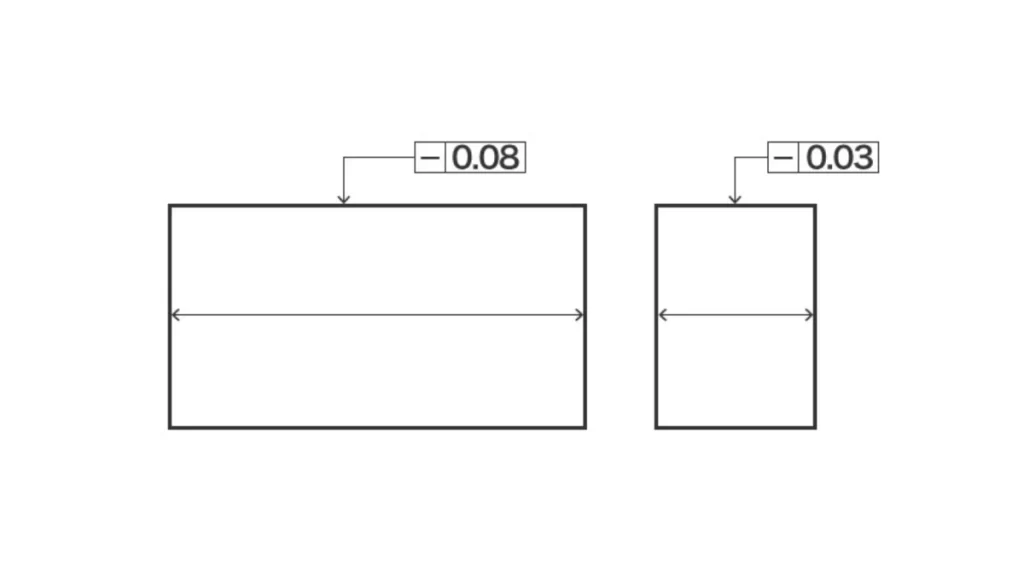
When you use this callout on a surface, it regulates the straightness of the surface. The range of the acceptability zone is above and below the ideal surface. It restricts the amount to which the surface can vary.
Surface straightness checks any line on the surface. It will be used in two ways. The first is on flat surfaces such as the face of a cube. Second, on cylindrical surfaces along their cylinder.
The tolerance zone in the two cases resembles two parallel lines. These are lines that are above and below the surface. This gives your part a two-dimensional surface area.
Axis Straightness
Straightness of an Axis
It is also possible to regulate the axis straightness with the help of a GD&T callout. The axis has to remain within the limits to have a proper assembly. The line of the median is not bent too much by straightness.
In this case, the tolerance zone is not above or below the surface. Instead, it takes the shape of a cylinder around the axis. To pass the part, your axis should be within this cylinder.
Try Prolean Now!
Feature Control Frame of Straightness GD&T
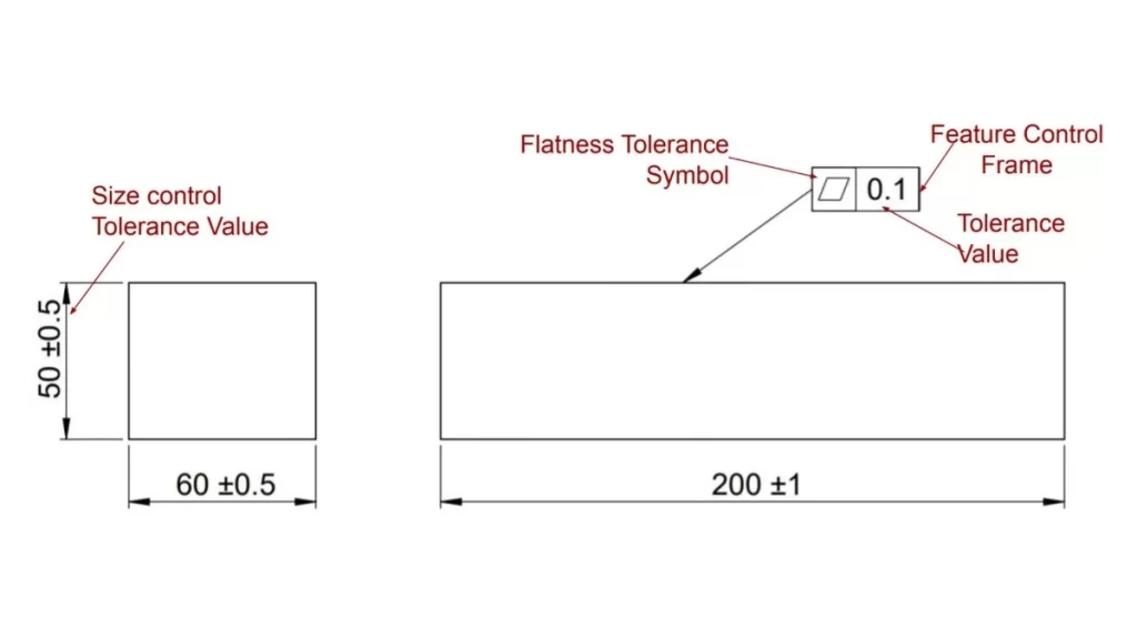
The feature control frame gives you all the details of tight tolerance machining. It has the straightness symbol and tolerance displayed.
Surface straightness FCF
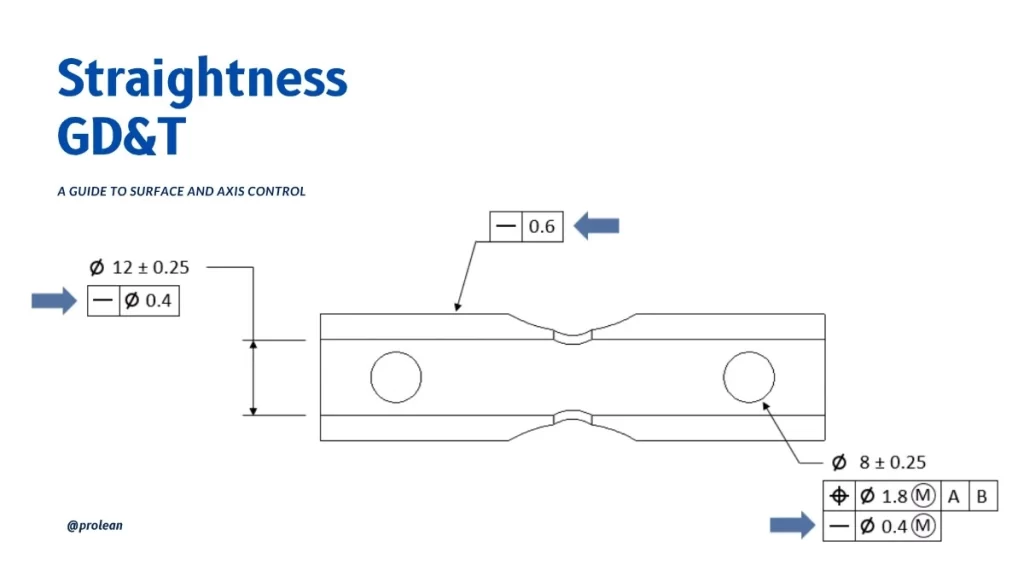
The symbol of surface straightness is a short line horizontally oriented. It displays your tolerance value and possible modifiers, such as maximum material condition. The straightness geometric tolerance zone is vast, so there is no need to have additional symbols. Here, you do not require a datum. The leader’s arrow indicates the surface you are in control of.
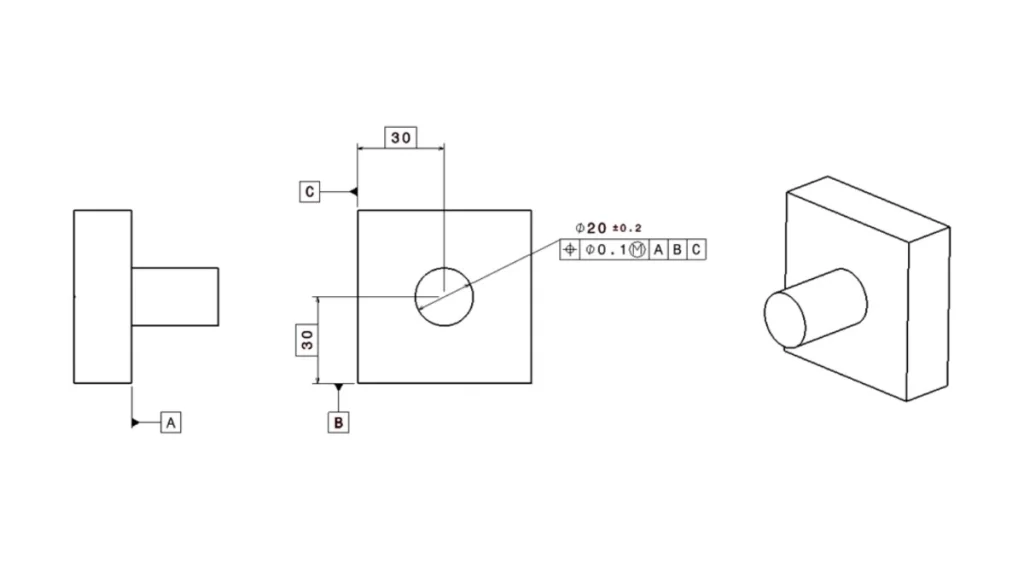
Axis straightness FCF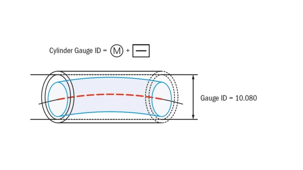
Measuring Straightness of Pipe
The frame of axis straightness is similar to the straight FCF, with the only exception. The second box has a diameter symbol since the toleranced area is a cylinder. The leader arrow is directed to the diameter part dimension as opposed to the surface.
The arrow’s location affects the callout, dictating a feature’s axis/centre plane. And when you see the arrow pointing to a size dimension, you are aware that this is the dimension that governs the straightness of the axis.
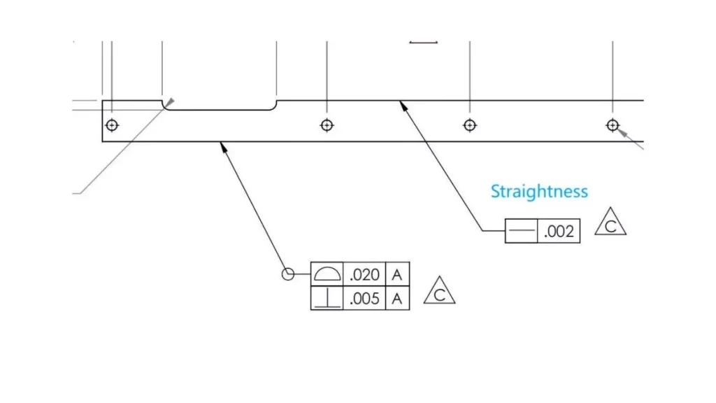
Straightness Callout and Symbol
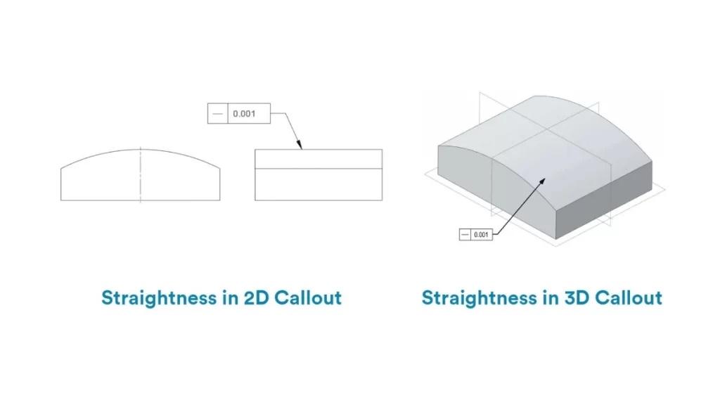
Straightness in 2D & 3D Callouts
It’s easy to show the symbol of straightness in drawings using the correct GD&T symbols. The symbol resembles a short, horizontal line. This is a callout you put on a surface or a feature of a specific size.
Bear in mind that straightness does not mean a datum. This distinguishes it from other symbols, such as parallelism. It is a form that is controlled without being anchored.
However, there are two principal applications of straightness, which you ought to be aware of. One governs the surface straightness, and the other regulates the straightness of the median line.
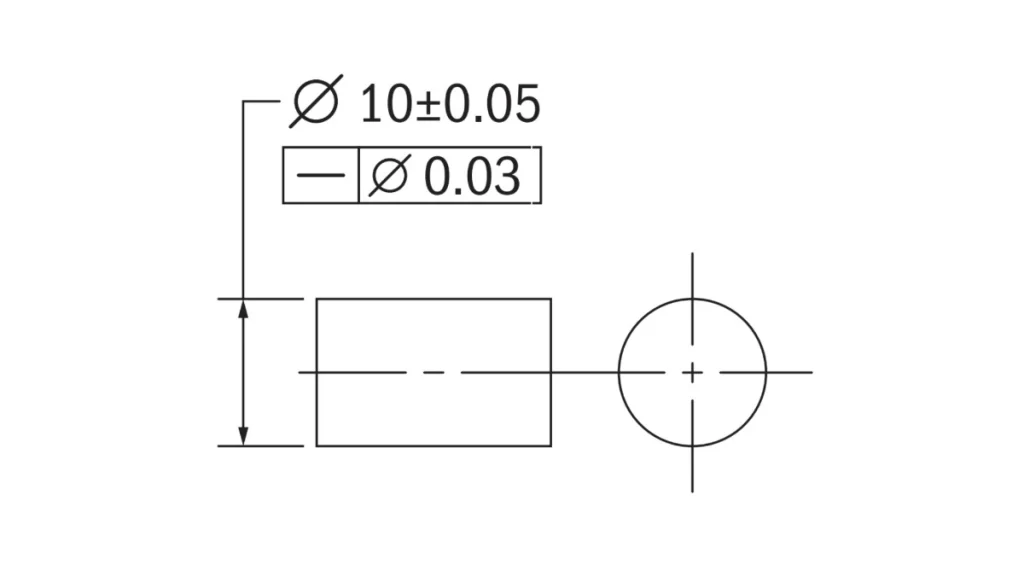
Straightness on Derived Median Line in GD and T
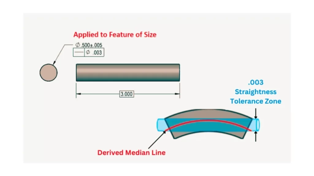
Derived Median Line Straightness
The resultant central line is the non-existent axis of your part. It is commonly used with cylindrical shapes. Applying straightness tolerance in this case controls the straightness of the axis.
The area of the tolerance zone is a cylinder with a perfect axis. This area picks angles, curves, and irregularities of shape. It provides you with three-dimensional manipulation of the form of the feature.
To make this call out, you do not require a datum. Straightness does not refer to a datum, unlike other symbols, such as perpendicularity. This makes it easier to use.
MMC Callout Straightness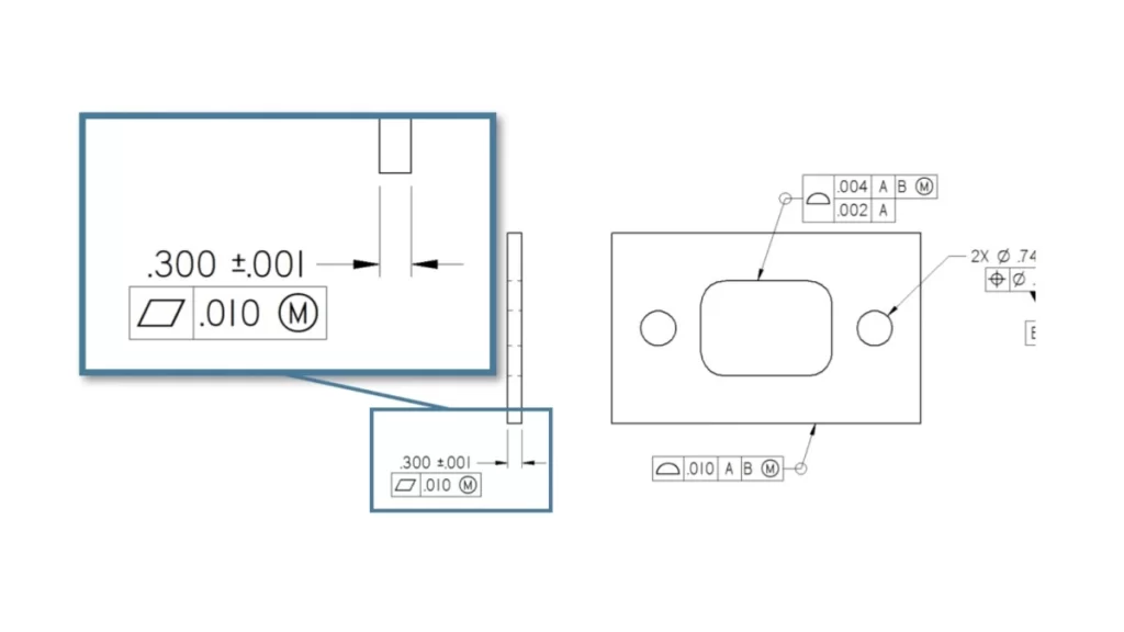
Maximum Material Condition (MMC)
Sometimes, you will find that the maximum material condition, MMC, is employed with straightness. MMC also ensures that your part is compatible with mating parts, even when large. The MMC of a shaft is the maximum diameter.
At MMC (Maximum Material Condition – the largest shaft size), the shaft must be perfectly straight within the defined straightness tolerance. The functional gō gauge hole diameter equals the MMC size of the shaft MINUS the straightness tolerance value specified at MMC.
Bonus Tolerance Explained
GD&T Bonus Tolerance
The bonus tolerance is used when your part is less than its maximum size. If your shaft diameter is smaller than the permitted one, you will have additional straightness allowance. For instance, a narrower shaft provides this additional space within the length of straightness.
If the shaft is undersized by 0.02 mm, you gain that amount as bonus tolerance for straightness when using the MMC modifier. You don’t lose flexibility and stay in control throughout the process.
This sophisticated feature assists you in coping with the variations present in manufacturing. It demonstrates the interaction between straightness and MMC to maintain the functionality of parts.
How to Measure Straightness of a Derived Median Line
When it comes to the straightness of the median line, you gauge it differently than surfaces. The most widespread method is a cylindrical gauge. This instrument is more or less a hole to inspect quality.
That has to be the case, whereby it becomes clear when you insert your part in your hole and it fits. Little interference in any place implies that your part is standard.
Alternatively, you may employ a coordinate measuring machine, or CMM. It takes some samples of the centre along the axis. However, this method is more time-consuming and applicable only to special cases.
In general, a quick quality check is obtained by the use of a cylindrical gauge. It will assist you in guaranteeing that the part functions well. However, if runout GD&T is specified, the inspection must also consider the part’s orientation and its relationship to a datum. It usually requires more advanced equipment, like a CMM or dial indicators on a rotating fixture.
Try Prolean Now!
What are the differences between straightness vs flatness GD&T?
Flatness In GD&T
You may mix up flat with straight; they are so alike. However, these two control different aspects in CNC machining. Let’s examine the significant distinctions.
Flatness is a geometric control that defines the overall evenness of a surface. Straightness only deals with one line. This implies that flatness is a complete area, whereas straightness is one dimension.
Flatness controls the variation of an entire nominally flat surface (a 2D feature) relative to a perfect plane (a 3D concept). Straightness controls the variation of individual line elements (1D features) either along a surface or of a derived median line relative to a perfect straight line (also a 3D concept).
Flatness only applies to a flat surface and needs the entire surface within the limits. Straightness can be applied to control line elements on any surface (flat, cylindrical, etc.). Besides, it derived the median line (axis/centre plane) of a feature of size. Centerlines are theoretical and cannot be toleranced; it is the derived median line of an actual feature (like a hole or pin) that is controlled.
Why Use Straightness Tolerance?
You apply straightness tolerance when the parts must be in contact with a line. It also identifies some critical surfaces upon which machining attention is laid. This assists in creating an ideal match and performance.
Hydraulic sleeves, tubes, and covers are essential for straightness control. These components require perfect contact to work under high pressures. Straightness ensures that the surfaces have tight requirements.
In pins and cylinder parts, it is necessary to be straight along the axis. It assists these parts in going into holes or bores. The callout ensures that there is a good fit at the largest size of the material.
Handle Your Engineering Projects with Prolean Tech
At Prolean Tech, our engineering team stands out in diverse manufacturing processes. We deliver test parts that closely match your final products using custom CNC service, rapid tooling, and injection molding.
We also help you review engineering drawings to ensure they meet all production requirements before prototyping or full-scale manufacturing.
Start your next project with confidence. Get a free quote from Prolean Tech today!
FAQ’s
Q1: What is straightness in GD&T?
Straightness in GD&T controls how straight a feature or line must be on a part. It limits the deviation from a perfectly straight line, ensuring the feature meets design requirements.
Q2. What are straightness and flatness?
Straightness controls the straightness of lines or axes, while flatness controls how flat an entire surface is. Both are geometric tolerances that ensure parts fit and function correctly.
Q3. What is the difference between flatness and straightness?
Flatness applies to all surfaces and controls their 3D shape. Straightness applies only to lines or axes and controls their 2D form. Flatness covers an area; straightness focuses on a single line.
Q4. What is the geometric symbol for straightness?
The geometric symbol for straightness is a simple horizontal line, like a short dash. This symbol appears in the feature control frame on engineering drawings.


0 Comments