Run Out Machining Guide
In CNC machining, accuracy is very important. Even a small error can affect how well a part works, how long it lasts, and how good it looks. One common error is called runout.
This happens when a tool or part spins slightly off-center, which makes it touch the material unevenly. This can lead to rough cuts, damaged surfaces, and tools wearing out faster — all of which reduce product quality and increase costs.
There are two main types of runout: axial and radial. It’s important to know how to measure them and what they mean using GD&T symbols (Geometric Dimensioning and Tolerancing).
Runout control is important in many industries, like aerospace, automotive, and medical, to keep parts within the correct limits and make sure they work properly.
At ProleanTech, we help manufacturers deal with issues such as advanced CNC solutions and runouts with accurate engineering.
This guide will break down the basic principles of CNC runouts, detect industry-standard measurement methods, explain the GD&T symbols, and their applications. For now, let’s dive into what makes runout such a vital concept in machining.
Check here: CNC Machining Process Explained — your go-to guide for understanding precision machining from the ground up.
What is Runout in Machining? 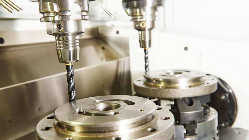
Runout in CNC Machining
The runout refers to the deviation of a rotating component from its ideal circular path. This deviation can cause inaccuracy in machining processes, which can affect both product quality and production efficiency. Runout is essential for manufacturers to customize their operations and distribute high-quality parts.
Understanding the runout is essential for many reasons:
- Precision: High runout can lead to dimensional inaccuracy, which affects assembly and function.
- Tool Life: Excessive runout causes uneven wear on tools, reduces their lifetime, and raises costs.
- Production efficiency: The runout can disrupt machining processes, which can increase the cycle time.
By effectively managing the runout, manufacturers can ensure product quality and operational efficiency.
Interesting Read: Soft Machining – Benefits and Drawbacks.
What Are the Two Types of Runout?
The runout in machining refers to a rotational inaccuracy where a spinning part or tool is distracted by its real axis of rotation. Instead of spinning smoothly around its center, the tool or workpieces create unwanted movements.
There are two primary types:
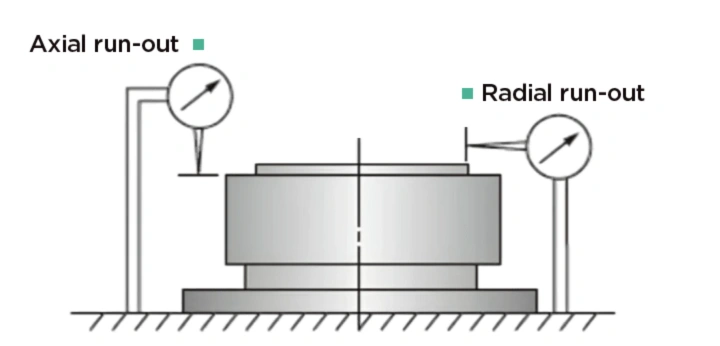
Axial and Radial Runout Diagram
| Feature | Radial Runout | Axial Runout |
| Definition | Deviation in distance from the center | Wobble along the rotational axis |
| Measurement Impact | Affects tool wear and precision | Affects alignment and positioning |
| Typical Causes | Misalignment, manufacturing defects | Bearing wear, installation errors |
1. Radial Runout
Radial runouts measure the variation of the part from the center of the runout rotation as it rotates. This measurement is necessary because high radial runouts can cause uneven wear on the device, causing incorrect measurements of the mechanical part.
2. Axial Runout
The axial runout refers to the wobble of a part with the axis of rotation. This type of runout can lead to misleading in applications requiring an accurate status, which can cause machinery malfunctions. For example, excessive axial runout of components such as bearings or shafts may result in premature failure.
Runout in GD&T (Geometric Dimensioning and Tolerancing)
In geometric dimensions and tolerance (GD&T), the runout is a central geometric tolerance. Geometric tolerance runout defines how much a rotating part can deviate from its ideal path. This standard method helps engineers clearly communicate the requirements. This ensures that parts fit together correctly and work as expected.
1. Circular Runout Symbol
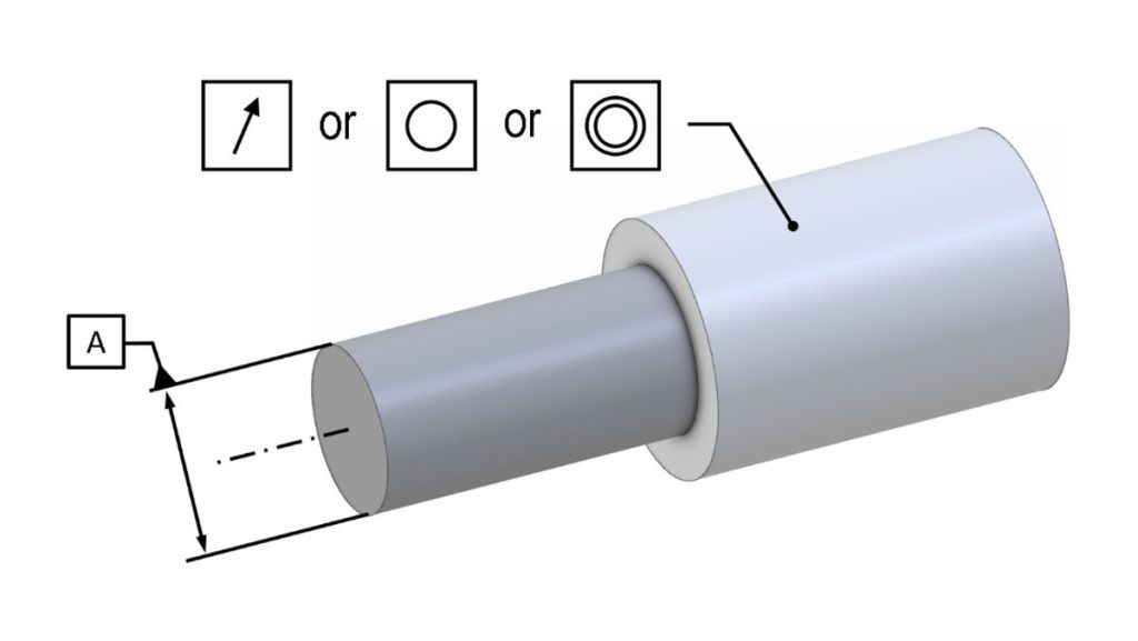
Circular Runout Indication
The circular runout symbol is used in engineering drawings to indicate tolerance in one part during circular motion. This symbol specifies how much distance may vary from the center of rotation to the surface of the part.
Circular runouts are measured at a specific radius. The acceptable limit is usually expressed in units such as millimeters or inches. For example, a spherical runout of 0.05 mm means that the part can be distracted as the part moves.
This symbol is necessary for applications where accuracy is necessary, such as in a motor vehicle or aerospace components. This ensures that parts such as gears or shafts operate smoothly. If the runout is more than the specified limit, it can cause vibration, wear, or failure in the assembly.
2. Total Runout Symbol
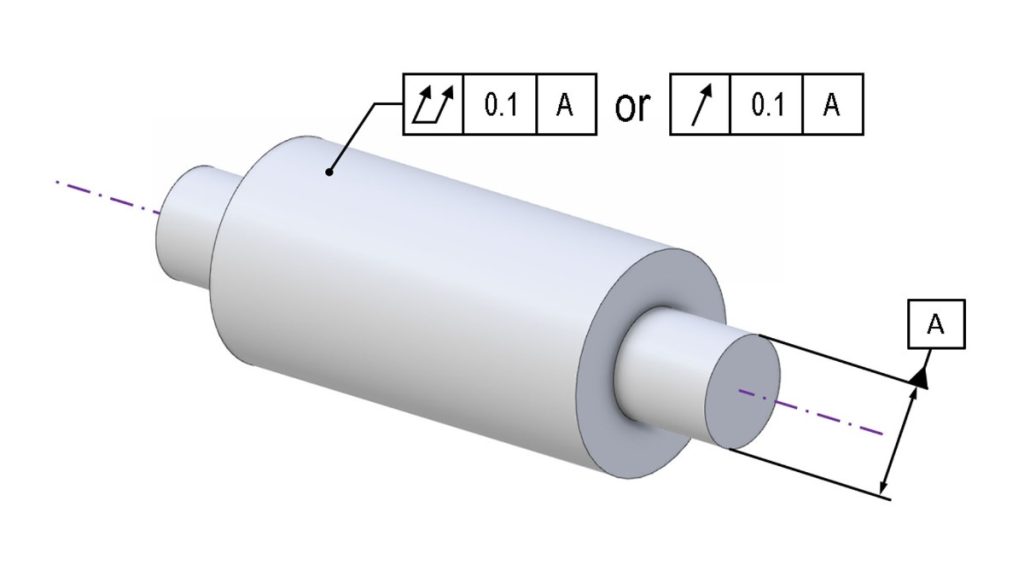
Total Runout Indication
The total runout symbol covers the entire rotational axis of one part. It accounts for both radial and axial variations. This means that it sees how much the surface of the part can go because it revolves around its axis.
The total runout is measured along the entire length of the part. Acceptable tolerance is also expressed in units like millimeters or inches. For example, a total runout of 0.1 mm means that the entire surface should remain within that range during rotation.
This symbol is essential for high-precision applications. This ensures that this part lives within the acceptable limits on its entire surface. Parts like bearings, which require high precision, greatly benefit from this specification. If the total runout is higher than the range, it can cause misalignment, which can lead to increased wear and low performance.
Using these symbols in GD&T, ProleanTech ensures that parts are manufactured for the required specifications and improves the overall quality and reliability of the final product.
Interesting Read: https://proleantech.com/production-cycle-time-in-cnc-machining/
Try Prolean Now!
Understanding Runout vs Total Runout
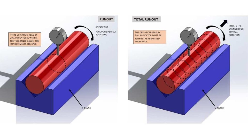
Runout vs. Total Runout Measurement
The runout refers to the deviation of a rotating part from its ideal circular path. It can either manifest as radial runout, which measures how different the distance from the center of rotation is, or axial runout, which assesses Wobble with the axis. Both types of components are essential for evaluating accuracy.
The total runout, however, provides more comprehensive measurements. It considers both radial and axial deviations simultaneously. It also ensures that the entire surface of the part remains within the specified boundaries as it rotates.
This measurement is essential for high-collective applications where minor deviations can lead to critical operating issues.
| Feature | Runout | Total Runout |
| Definition | Measures radial or axial deviation | Measures both radial and axial deviations together |
| Scope | Refers to either type individually | Comprehensive, covering the entire surface |
| Measurement | Focuses on distance from the center | Assesses variation along the whole length of the part |
| Precision Requirement | Generally less stringent | More stringent, critical for high-precision applications |
Understanding the differences between runout and total runout is essential for ensuring the accuracy and reliability of machined components.
GD&T Example: Understanding a Shaft
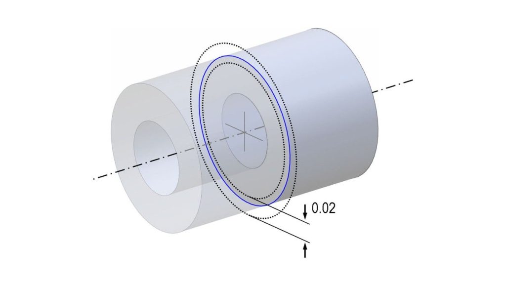
Circular Runout Tolerance Zone
Imagine a cylindrical shaft requiring a circular runout tolerance of 0.02 mm:
- A dial indicator is positioned at a cross-section.
- The part is rotated 360°.
- If the indicator reading fluctuates beyond 0.02 mm, the part fails.
Now consider total runout:
- The dial indicator moves along the shaft’s surface.
- Any variation in straightness or concentricity throughout the shaft must remain within 0.02 mm.
This control is vital in turbine shafts, spindle assemblies, and gearbox components.
Curious about how production time affects tolerance? Check our guide on Production Cycle Time in CNC Machining.
How to Measure Runout?
Precise measurement of runout is essential in CNC machining, especially for industries that demand tight tolerances such as aerospace, automotive, and medical devices. Even slight runouts can lead to rejected parts, low tools life, and mechanical failures. There are three most common and effective ways to measure the runout below:
1. Dial Indicator
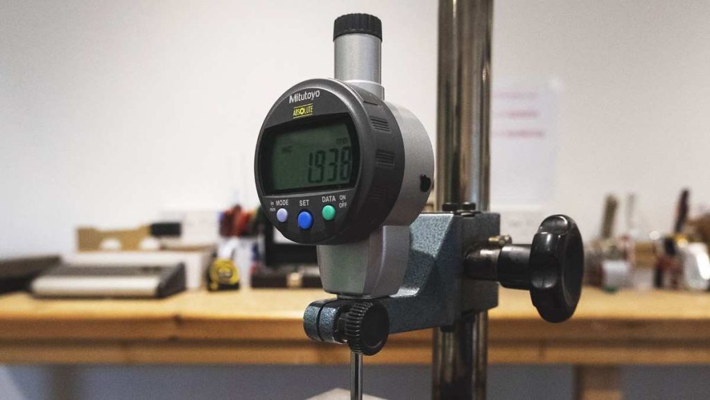
Dial Indicator for Runout
- This is the most widely used tool for basic runout measurement:
- Protect the part or equipment in the spindle or chuck.
- Give the position to the dial indicator so that its tip touches the surface.
- Slowly rotate the half part manually.
- The needle movement on the dial shows the total indicator reading (TIR), which represents the runout value.
This is a simple, cost-effective method ideal for the quick examination of shafts and cylindrical parts.
Need high-precision machining? Explore High-Accuracy CNC Machining Solutions
2. Laser Measurement
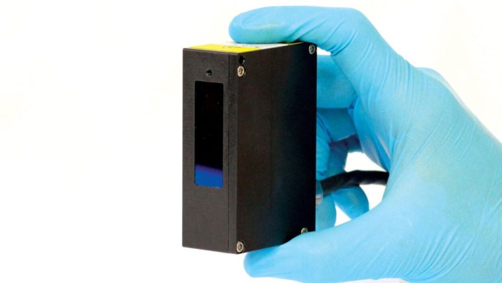
Laser Distance Measurement Sensor
Laser displacement sensors provide non-contact, high-accuracy measurements. These systems are ideal when you need to measure a micron-level runout on rotating devices without physical contact. They are usually used in automatic production lines for real-time monitoring.
3. Coordinate Measuring Machine (CMM)
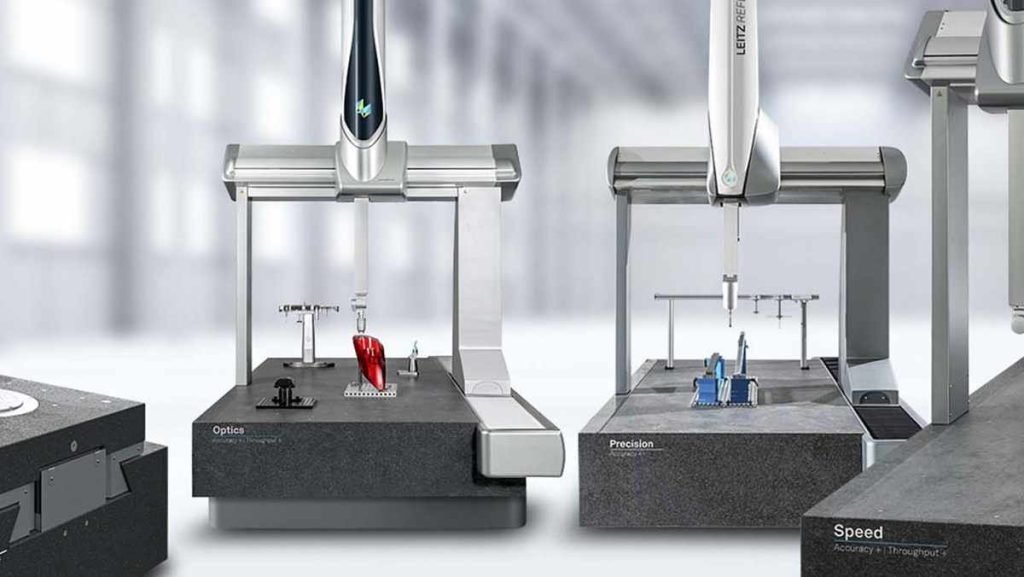
Advanced Coordinate Measuring Machines
CMM is perfect for 3D measurements of complex geometry. They can detect both radial and axial runouts in an entire part. CMM is preferred in quality control laboratories when verifying parts with extremely tight GD&T requirements.
Try Prolean Now!
What is the Purpose of Runout?
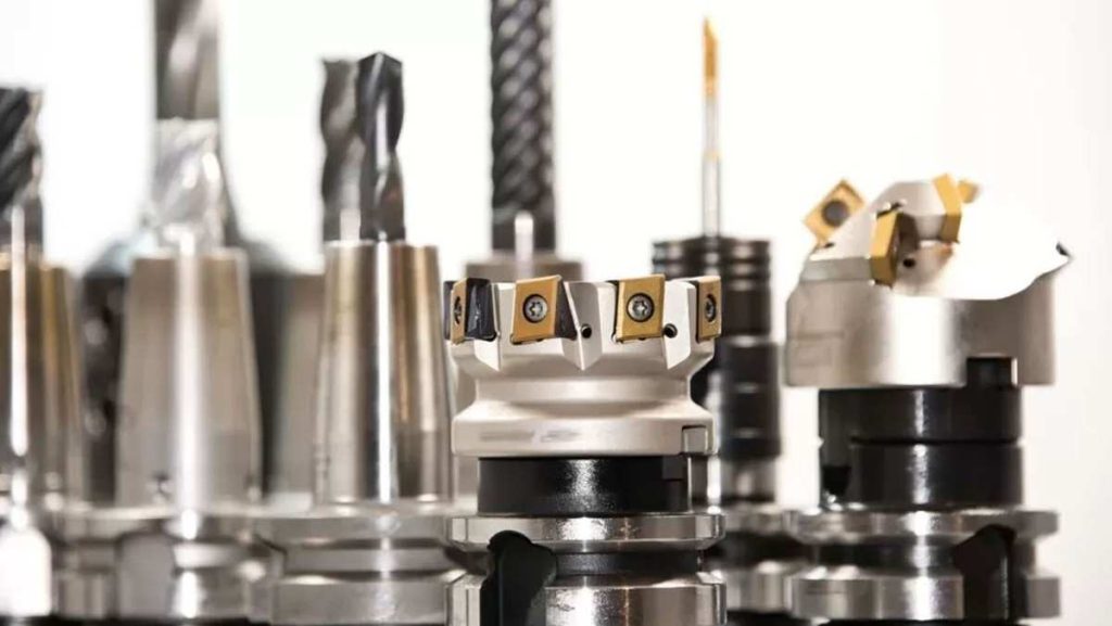
Assorted CNC Milling Tools
It is necessary to control the runout to maintain the accuracy, efficiency, and quality of CNC-machined parts. When the runout is minimized, the components fit perfectly within the assembly, ensuring tight mechanical alignment.
It is mandatory in industries such as aerospace, medical, and automotive, where a slight mistake can also give rise to issues of performance failure or safety.
Reducing the runout helps to preserve functionality by reducing vibrations during machining or in use. Additional vibrations can increase display issues, shorten machine life, and increase downtime.
Another essential benefit is improving the surface finish. The correct running devices for its axis create smooth, more consistent surfaces, while the runout introduces irregularities.
Finally, the tool life is greatly enhanced when the runout is controlled. Wrong tools experience uneven forces and wear rapidly, increase costs, and require more frequent replacement.
Want the best results with the right material? Check our Common Materials for CNC Machining.
Real-World Consequences of Excessive Runout
Excessive runouts can lead to serious production challenges.
The instruments wear unevenly, reduce their lifetime, and require frequent replacement. The misalignment caused by the runout often causes component failure, especially in high-stakes applications such as engines or medical devices.
Additionally, the runout causes incorrect deduction, compromising the accuracy of the part and the quality of the surface. It not only leads to a high rejection rate, but also increases scrap and production costs.
At Proleantech, we combat runouts using state-of-the-art CNC machines, strict quality checks, and accurate equipment holders. Our team ensures that all parts are completed for accurate tolerance to maintain functionality and performance.
For deeper insights, read Metal Cutting with CNC Machines Explained
How to Check Runout on a Shaft?
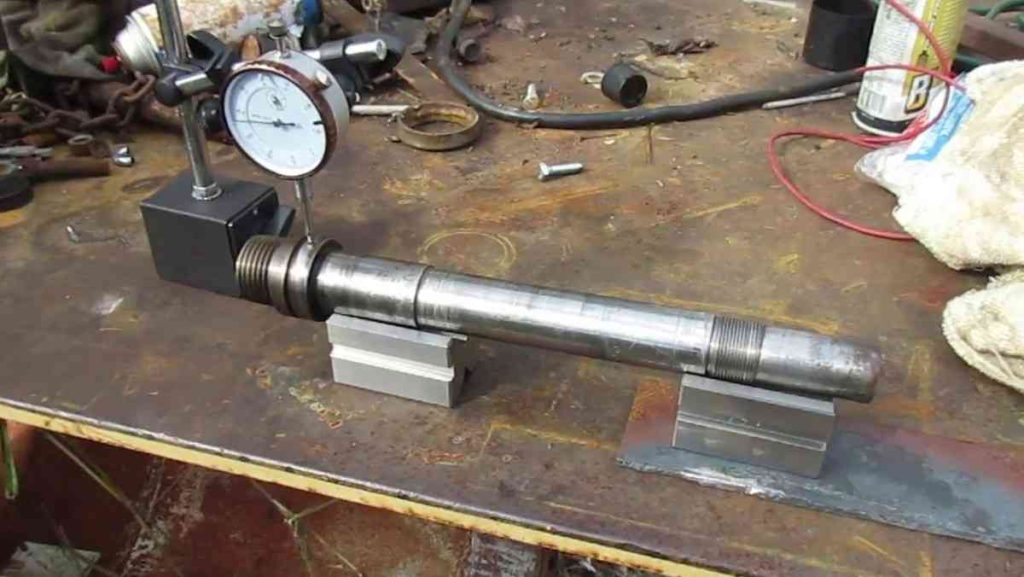
Checking Shaft Runout with Dial Indicator
To check the runout on a shaft, first mount the shaft between the centers using a collet safely, or to avoid movement. Then, give the position to a dial indicator so that its tip contacts the surface of the shaft at 90 degrees.
Slowly rotate the shaft with one hand and inspect the dial reading. Any deviation indicates the runout. The total indicator reading (TIR) is calculated by subtracting the lowest reading from the highest reading during full rotation.
This process helps identify issues such as bent shaft, worn bearings, or inappropriate mounting, which are important to maintain accuracy in high-concerned applications.
Why Prolean is the Go-To Solution for Machining?

Why Prolean for Machining?
ProleanTech – Your Custom Parts Manufacturing Partner. We specialize in high-quality custom parts that meet strict tolerances. Our team is experienced in managing runout and total runout, ensuring your components perform optimally.
We use advanced technology and equipment to measure and control runout effectively. This helps us deliver parts that fit together perfectly and function as intended. Our commitment to quality means we continuously monitor our processes.
ProleanTech also offers a wide range of materials and services. Whether you need CNC machining, 3D printing, or rapid prototyping, we have the expertise to meet your needs. Choose Prolean for reliable, accurate, and efficient machining solutions that enhance your production capabilities.
Ready to choose your supplier? Read Top 9 CNC Machining Manufacturers in The World
Wrap Up
Understanding and managing the runout is essential for anyone involved in machining processes.
By implementing proper measurement techniques and following GD&T standards, manufacturers can ensure high-quality production and reduce costs. Effective runout management is an identity of accurate engineering and is an essential factor to maintain a competitive advantage in the market.
For those interested in enhancing their machining processes, ProleanTech is your go-to partner for custom parts manufacturing. We offer a wide range of CNC machining services tailored to meet your specific needs.
Contact us now to discuss your requirements or get your quote now for competitive pricing and expert solutions. Explore our China CNC machining services today!
FAQs
Q1. What is a Runout in Machining?
The runout refers to the deviation of a rotating part from its actual circular path, which is accurate in machining and affects quality. It is measured as a difference between the maximum and minimum distances from the center of rotation to the surface of the rotation during rotation.
Q2. What is Mechanical Runout?
Mechanical runout describes the variation in the rotational axis of a mechanical component, which may be due to the creation of defects, wear, or inappropriate installation. It is essential to identify and correct mechanical runouts to maintain accuracy in machining.
Q3. What is the Purpose of Runout?
The purpose of measuring the runout is to ensure accuracy, increase the equipment life, and improve production efficiency. Understanding the runout allows manufacturers to reduce errors, reduce costs, and maintain high-quality standards in their products.
Q4. How is Runout Calculated?
During rotation, the runout is calculated by measuring the maximum and minimum distances from the center of the rotation to the part surface. The difference between these values provides the total runout measurement, which helps manufacturers to assess the accuracy of their machining processes.
Q5. What causes Runout?
Many factors, including inappropriate mounting, worn bearings, misalignment, or faulty parts, can cause runouts. It is necessary to identify the root cause to maintain effective improvement and maintenance accuracy.
Q6. What is the Difference Between Stamped and Runout?
Stamped refers to parts created through a stamping process, while the runout describes deviations in the path of a rotating part. Stamping processes usually do not include rotational components, which makes the runout irrelevant in that context.
Q7. What are the Two Types of Runout?
There are two types of runouts: Radial runout and axial runout. All types of machine accuracy present unique challenges and implications, requiring various measurements and corrective strategies.
Q8. What is the Runout of a Mill?
The runout of a mill shows how much the cutting equipment is deviated from its actual rotational path while milling. High runouts can eliminate bad surfaces and cause impurities in mechanized components, which affects overall quality.
What is runout in machining?
Runout in machining refers to the inaccuracy or deviation that occurs when a rotating object, such as a spindle or shaft, does not rotate perfectly around its central axis. This deviation can cause uneven wear and tear on tools and workpieces, reducing their lifespan and overall performance.
What is GD&T runout?
GD&T runout is a geometric tolerance that controls the amount of runout (both radial and axial) that a feature or surface can have when referenced to a datum axis or plane. There are two types of runout specified in GD&T: circular runout and total runout.
What is the difference between radial and axial runout?
Radial and axial runout refers to variations in distance from the central axis or reference plane. Radial runout affects roundness, while axial runout influences flatness and parallelism.
What is the runout measurement?
Runout can be measured using a dial indicator or a laser measurement system. The part is rotated, and the measurement device is placed against the surface being measured. The device will indicate the amount of runout as the part rotates.
What are the common causes of runout?
Common causes of runout include spindle error, tool holder error, and workpiece clamping error. Any inaccuracies or misalignments in these components can lead to runout in the machined part.
How to calculate circular runout?
Circular runout is calculated by a height or dial gauge. First, fix the part using a V-block or a spindle along its datum axis. And then pin of a dial gauge is then set on the circular feature and the dial is set to zero.
How can runout be reduced?
Runout can be reduced by ensuring proper clamping of the workpiece, using high-quality tool holders with precise concentricity and balance, and regularly checking and maintaining the spindle to ensure it is accurately aligned and free of any inaccuracies or damage.


Can add how to calculate machining allowance for given run out to avoid un macihened surface
Yes! But worth remembering is that ” Machining allowance isn’t typically calculated directly from runout. They serve two different purposes in manufacturing:
Machining Allowance: This is the extra material left on the surface of a casting or a forging to enable the removal of any defects and to achieve the final shape, size, and finish by machining or grinding. This allowance is given to ensure that the final finished size is achieved after machining.
Runout: This refers to the deviation from a true circular rotation of a shaft or disc in machinery. It is the measure of how much one point on the outer surface of a rotating object deviates from its turning radius as it rotates.
However, if you’re trying to ensure that a part that has runout is machined to be true, then the machining allowance would need to be at least equal to the amount of the maximum runout.
For example, if you have a shaft that has a runout of 0.2mm, you’d need at least a 0.2mm machining allowance to ensure that when you machine the part, you can achieve a true circular rotation.”