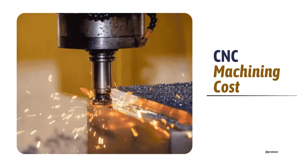
CNC Machining Cost
When you plan a CNC-machined part, usually, several factors define the cost. These are design, material, and quantity required. Your design determines which machine to use, such as a three-axis, five-axis, or CNC turning machine. Material affects cost based on its price and the ease of machining. Quantity affects the cost/part because producing more parts lowers the unit cost.
CNC machining is a subtractive process. It removes material from a solid block using precise cutting tools. This process shapes accurate parts while reducing manual intervention. It also speeds up production and maintains high quality across large batches.
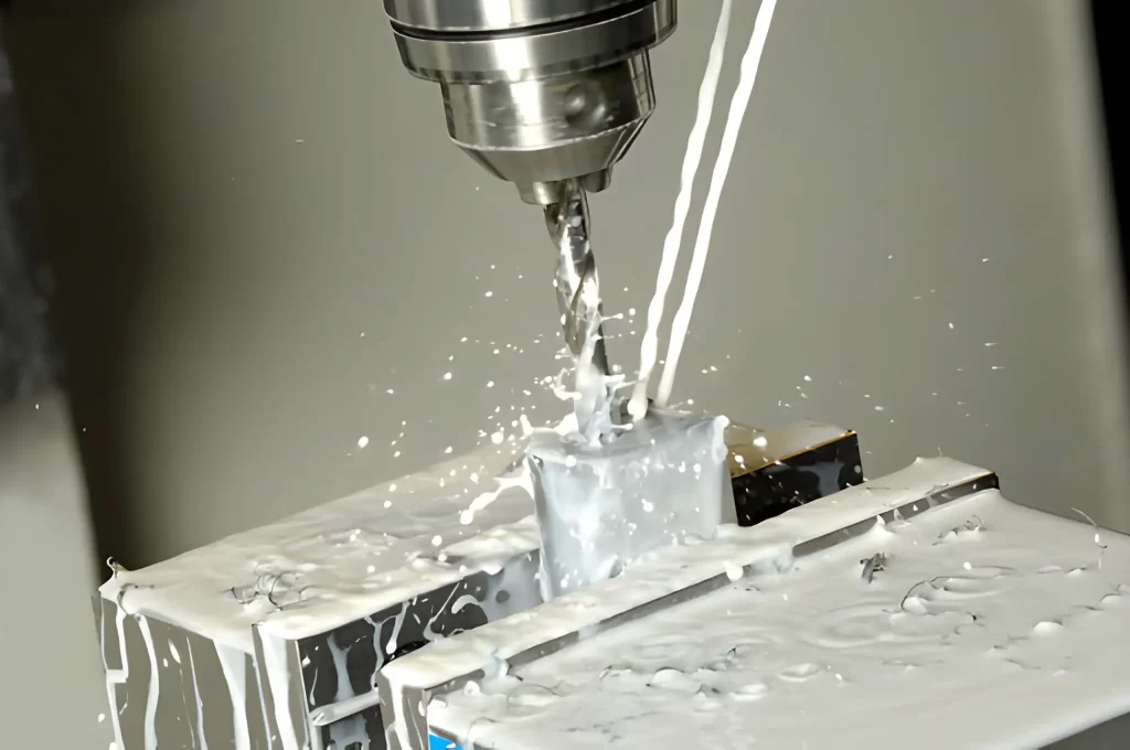
CNC Drilling
Machining costs also vary depending on location and machine use. For example, in CNC machining China typically costs between $ 10 and $ 21 per hour. In the United Kingdom, the prices of CNC machining companies can reach approximately £ 30 per hour. Labour, machine time, and energy consumption are the primary factors that drive these costs.
At Prolean Tech, we make CNC machining efficient and cost-effective. Our team helps you optimise part designs, select the right materials, and plan production volumes to control costs. You can always expect high-quality, precise parts to be delivered on time without overspending, as the company adheres to strict ISO standards.
This guide explains the key factors that determine the CNC machining costs, how to calculate them, and practical ways to reduce expenses without compromising part quality.
What are the Factors Affecting the CNC Machining Cost
Several variables influence the overall cost when planning a CNC machining part. These factors include machine type, machining time, labour, material, design complexity, tooling, after-processing, and volume production. Being aware of these factors helps you make the right choices and spend efficiently.
Machine Type and Cost
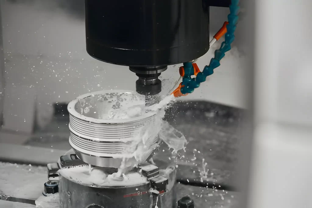
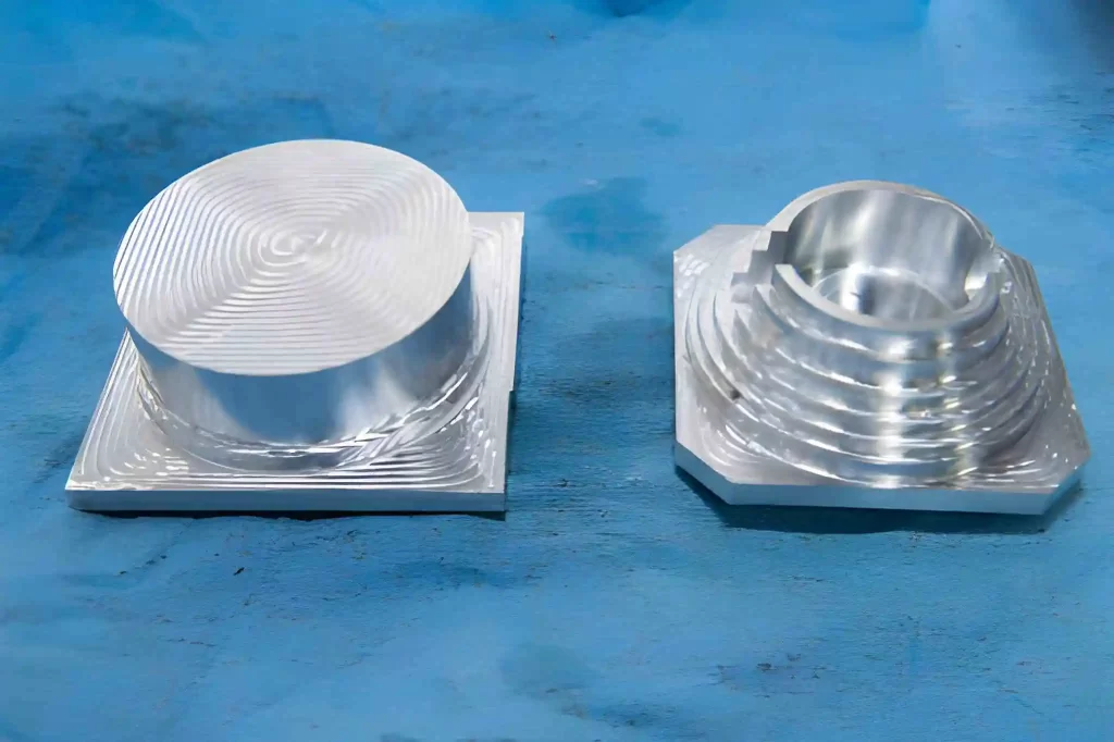
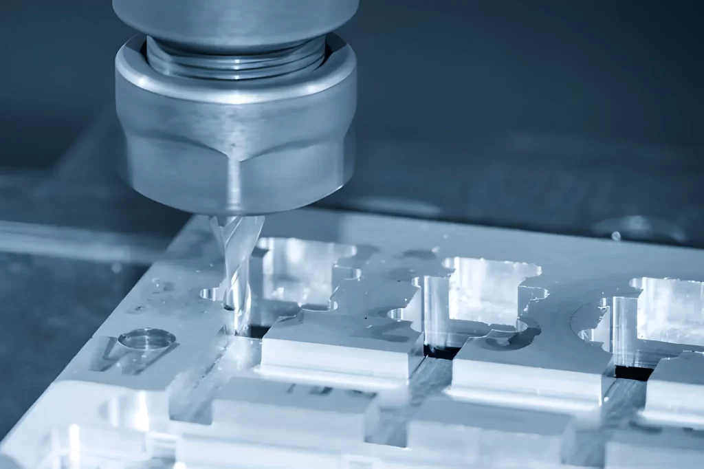
CNC Milling Part
The choice of the machine will have a direct influence on cost. CNC machines are typically 3-axis or 5-axis machines, whereas rotating machines are CNC turning machines. Machines with more axes can generate shapes with complex geometries at a higher speed, but are more expensive to operate.
As a point of reference, the 3-axis machining costs approximately $ 40/hour, CNC turning machines cost around $ 35/hour, and the multi-axis machines cost between $ 75 and $ 125/hour. (Read also: 3-axis vs 5-axis CNC machining)
The price is also influenced by machine size, speed, power, and configuration. Moreover, it is considered that milling operations are more costly compared to turning and require more setup.
Machining Time
Besides machine type, CNC machining cost is highly dependent on the time taken to finish a part. Increased machining durations raise labour costs, energy consumption, and operational expense. Complex parts/components take more extended hours. CAM software, combined with a 3D CAD model, can be used to estimate machining time and minimize unforeseen costs accurately.
Labor Costs
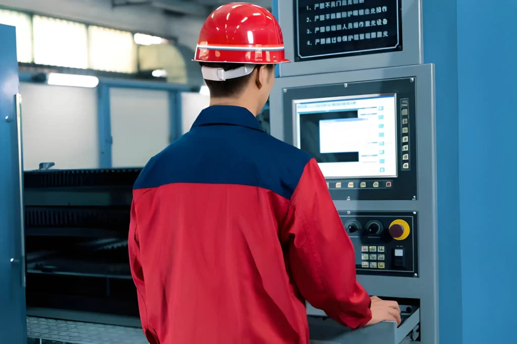
Operator Controlling CNC Machine Operation
CNC machining, however, minimizes human interaction; yet, operators and designers are still required. The labour cost includes: 3D CAD model design, programming of the machine, and the handling of the machining process. More complex components require additional skills and, as a result, come at a higher cost. Additional work may be necessary for assembly, finishing, and transportation of parts, which further increases the price.
Material Selection
Steel Threaded Machined Part
The cost of CNC machining is also dependent on the material selection. Metals and plastics are varied in terms of price, machinability, and durability. Aluminium is an economical and easy-to-machine material. Rigid metals like stainless steel and brass are more. Titanium alloys are more expensive than the ones mentioned above, as they also require specialized equipment and processing techniques. Nylon, Delrin, and ABS are engineered plastics that are less expensive to machine. The correct choice of materials is a trade-off between performance and cost.
Design Complexity
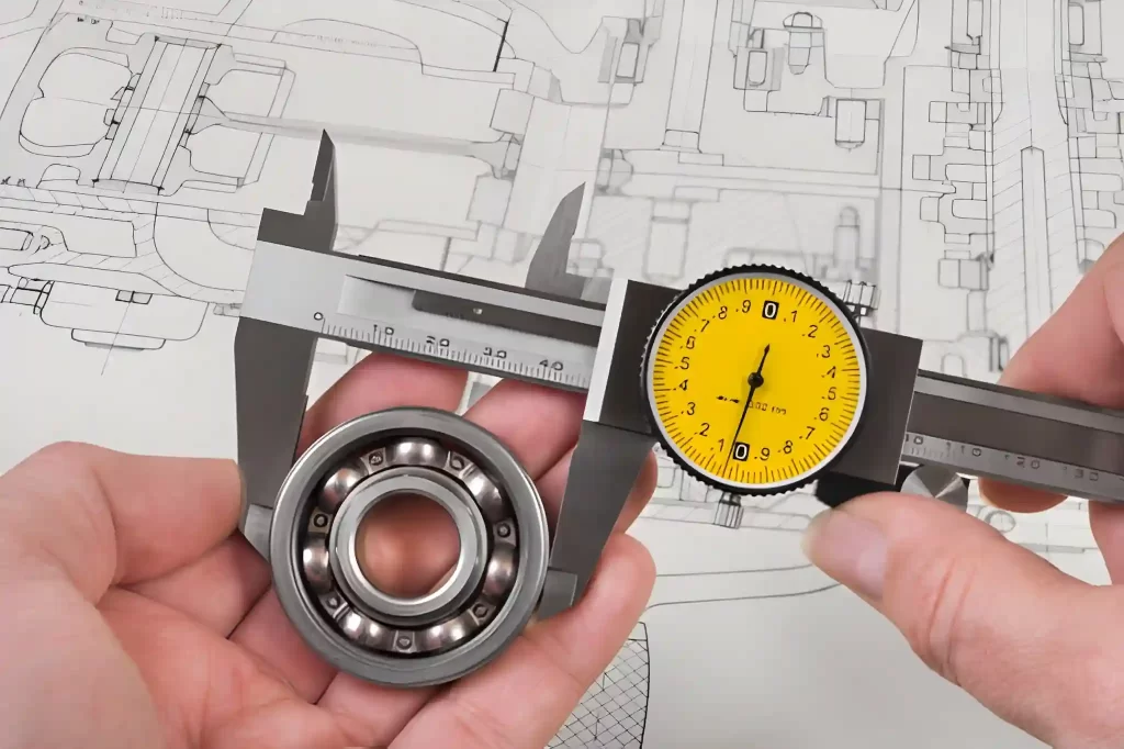
Bearing Dimensional Measurement Using Digital Calliper
Part design and geometry are also significant factors in calculating CNC cost. Complicated shapes, deep pockets, thin walls, or non-standard shapes demand improved machines, additional tool changes, and increased setup time. On the other side, a less complex machining design saves time and machining cost. Multi-axis machines or specialized tools are often required for detailed designs, which adds cost.
Tooling Costs
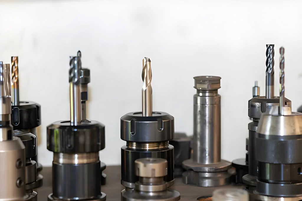
CNC Machining Tool Set
Some machining projects require special tools in case the desired shape cannot be attained by using standard tooling. Custom tooling also leads to an increased cost.
Surface Finish and Post-Processing
Following machining, the parts may require further finishing to remove marks or enhance features. Processes such as sanding, coating, anodising, painting, chroming, galvanising, or brushing increase the cost. Additionally, extra tools, materials, and labour may be required in post-processing.
Production Volume
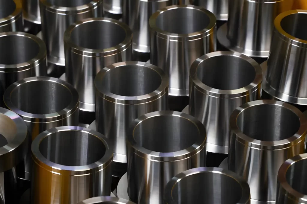
Shiny Steel Machined Parts In Bulk
The quantity manufactured influences the unit cost. An increase in production volumes or simple large scale machining decreases the cost per part, as the set-up and preparation costs are divided among more parts. This renders large-scale production more economical.
How can you Optimise Your CNC Machining Costs?
To manage costs effectively, you can:
- Simplify your part design. This will help you reduce machining time and tool changes.
- Choose materials considering your part’s actual use, its properties, and machinability.
- Plan production volumes to keep economies of scale.
- Minimise post-processing when possible.
At Prolean Tech, we guide you in optimising design, selecting materials, planning production, and controlling costs. Our expert team ensures your parts are manufactured on time, with desired accuracy and precision.
CNC Machining Cost Calculation: Formula, & Material Impacts, & Others
Calculating CNC machining costs can be complex. Costs depend on part complexity, material, machine type, production volume, and finishing requirements. There is no single formula that works for every part, but we can break it down for clarity.
Estimating Cost Using a Formula
You can estimate costs using this approach:
Estimated Cost = Material Cost + Setup Cost + (Machining Time × Hourly Rate) + Finishing Cost
- Material Cost: The price of the raw material used in the part.
- Setup Cost: It includes preparing the CNC machine, such as programming and labour.
- Machining Time × Hourly Rate: Time needed to machine the part multiplied by the machine’s hourly rate. Three-axis machines typically cost $10 to $20 per hour. At the same time, multi-axis machines range from $20 to $40 per hour.
- Finishing Cost: Additional processes like polishing, anodising, and coating, etc. (Also read: rapid prototyping cost)
Material Machinability
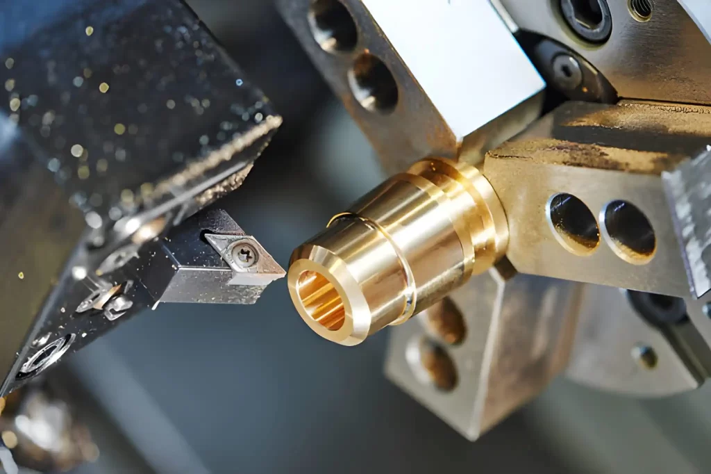
Brass CNC Turning
Machinability affects cost significantly. It measures how fast a material can be cut and how it impacts tool wear. Materials that are easier to machine take less time and reduce tool wear. Coolant systems can improve machinability by reducing heat and friction.
Common materials include:
Aluminium Part Milling
- Aluminium: 5 to 10 dollars per pound. It is easy to machine, has minimal tool wear, and is faster to process.
- Steel: 8 to 16 dollars per pound. It has moderate machinability and requires more effort and time than aluminium.
- Stainless Steel: Its machining costs range between $1.87 and $3.14 per pound. Complex to machine, increases machining time and tool wear.
Choosing materials with higher machinability lowers costs. However, ensure the material meets the part’s requirements, such as strength and corrosion resistance.
Try Prolean Now!
CNC Machining Costs Overview With Respect to Part Size, Material, Quantity, and Lead Time
CNC machining prices depend on machine type, material, part size, finishing, and quantity.
Standard CNC Machining Costs
|
Machine Type |
Part Size |
Material |
Quantity (pcs) |
Unit Price (£) |
Lead Time (Days) |
|
3-axis CNC |
Small (50 × 50 × 20 mm) |
Aluminium |
1 |
250 |
6 |
|
3-axis CNC |
Small (50 × 50 × 20 mm) |
Aluminium |
100 |
124 |
14 |
|
3-axis CNC |
Small (50 × 50 × 20 mm) |
Stainless Steel |
1 |
432 |
7 |
|
3-axis CNC |
Small (50 × 50 × 20 mm) |
Stainless Steel |
100 |
260 |
18 |
|
3-axis CNC |
Large (170 × 210 × 150 mm) |
Aluminium |
1 |
1,210 |
8 |
|
3-axis CNC |
Large (170 × 210 × 150 mm) |
Aluminium |
100 |
691 |
20 |
|
3-axis CNC |
Large (170 × 210 × 150 mm) |
Stainless Steel |
1 |
1,670 |
8 |
|
3-axis CNC |
Large (170 × 210 × 150 mm) |
Stainless Steel |
100 |
1,066 |
30 |
|
5-axis CNC |
Small (50 × 50 × 20 mm) |
Aluminium |
1 |
1,757 |
10 |
|
5-axis CNC |
Small (50 × 50 × 20 mm) |
Aluminium |
100 |
392 |
16 |
|
5-axis CNC |
Large (50 × 185 × 435 mm) |
Aluminium |
1 |
979 |
7 |
|
5-axis CNC |
Large (50 × 185 × 435 mm) |
Aluminium |
100 |
662 |
22 |
|
CNC Turning |
Small (43 × 11.5 mm) |
Aluminium |
1 |
29 |
4 |
|
CNC Turning |
Small (43 × 11.5 mm) |
Aluminium |
1,000 |
1.64 |
7 |
|
CNC Turning |
Small (43 × 11.5 mm) |
Stainless Steel |
1 |
36 |
4 |
|
CNC Turning |
Small (43 × 11.5 mm) |
Stainless Steel |
1,000 |
2.30 |
7 |
Get more insights on: high volume CNC machining
How to Reduce CNC Machining Costs
When you understand the factors that influence CNC machining costs, you can make the necessary adjustments to reduce costs while maintaining quality in the parts.
Limit Finishing Processes
The incremental finish incurs labour, machine time, and set-up costs. Choose a material with minimal post-finishing requirements. This saves general expenditure.
Choose Cost-Effective Materials
Aluminium is easy to machine and minimises tool wear. The use of appropriate materials that prove to be more cost-effective can reduce the overall cost without compromising strength and performance.
Increase Production Volume
The more the volume of production of parts, the lower the unit cost. In contrast, low volume CNC machining incurs high per-part unit production costs. The increased volumes support setup costs, which are dispersed across more parts. It results in better economies of scale and shorter cycle times per part.
Avoid Thin Walls
For thin-walled components, special tools and high accuracy are required, which adds cost and time. Thick walls should be used unless the part functions require thin walls.
Use Rounded Internal Edges
Acute internal corners require special equipment. This raises the complexity of machining. Round edges help to make machining easier, minimise tool wear, and save money and time.
Minimise Deep Cavities
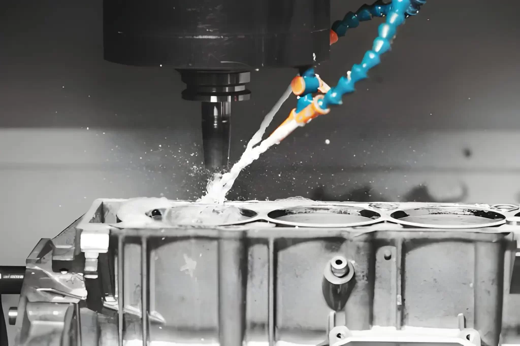
Milling Automotive Engine Component
Deep cavities require special equipment, e.g., ball-nose cutters, which adds to the expense. Therefore, avoid using excessively deep or elaborate cavities. Minimise or reduce depth or geometry.
Limit Threads
Threads increase the machining time and demand special tools. Limit the threaded features or replace them with other methods, such as thread milling, to minimise costs.
Avoid Overly Tight Tolerances
Tight tolerances require more time for machining and tool changes, often resulting in higher scrap production. Try to keep your design as simple as possible.
Standardise Hole Sizes
Off-the-shelf tooling can be used with standard hole sizes to save on set-up time and expense. Use standard thread sizes, such as UNC, UNF, or metric. Simple and planar holes are easy to machine and reduce costs.
Minimise Embossing and Text
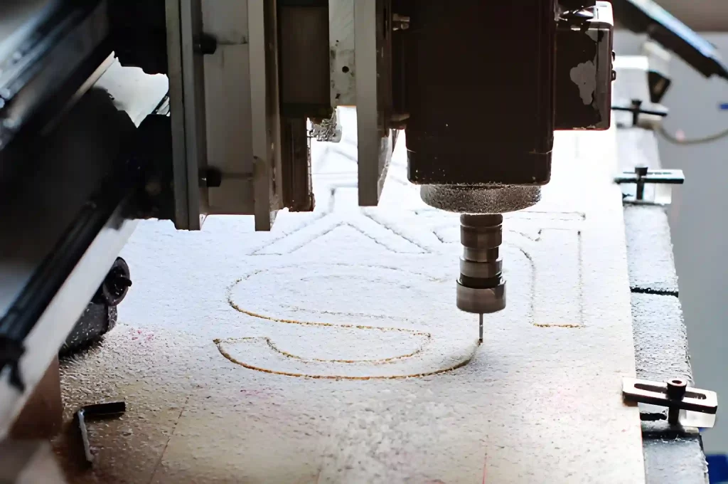
Text Engraving
Embossing or inscribing a text is a more complex process that consumes a significant amount of time during the machining process. These features should only be added where necessary, either functionally or due to branding requirements. These strategies will enable you to reduce CNC machining costs without compromising the quality and functionality of the parts.
Try Prolean Now!
Insights on Hourly Rates of CNC Machining: How Much Does CNC Machining Cost Per Hour?
Many CNC shops typically charge by the hour. The rate depends on your project and the machine used. Every job is unique so prices may vary.
Factors That Affect Hourly Rates
|
Factor |
Details |
|
Type of CNC Machine |
|
|
Tooling and Maintenance |
The cost includes wear and tear of cutting tools, repair, replacement, and regular maintenance. |
|
Machining Speed |
Standard machines complete work quickly but cost more per hour. New-generation machines can save time and reduce costs. |
|
Labour and Setup |
Skilled operators and programmers are needed. Complex parts or multiple setups raise hourly costs. |
|
Overhead and Location |
Electricity, rent, insurance, and shop location affect cost. Shops in developed areas usually charge more. |
Get an Affordable Online CNC Machining Solution with ProLean Tech
At Prolean Tech, you can save time and reduce costs on CNC machining by optimising design and production. Whether you need a few prototypes or larger production runs, we provide solutions to meet your goals efficiently.
Our team of experienced engineers ensures the production of precise, high-quality parts while maintaining services at a reasonable rate. Get your instant quote and see how we can help you streamline your manufacturing process.
0 Comments