In the vast domain of mechanical engineering, joining two components seamlessly is a task that demands precision and understanding. One prominent method used for achieving this is fitting. The basic principle revolves around inserting one component into another, where the former is slightly larger in size. The difference in sizes is purposeful to ensure a tight fit. This article elaborates on interference fitting, its association with engineering fits, and how it stands out in the world of precision engineering.
What are the Fits?
In the realm of mechanical engineering, the term “fits” often pops up. But what does it truly mean? Essentially, the concept of fits captures the relationship between two interlocking mechanical components. Typically, we’re discussing the interaction between a hole and a shaft. Depending on the application and design requirements, this relationship can be precisely defined. Understanding this relationship is essential for designing reliable and functional machines and devices.
The Genesis of Fits & Why it Fits Matters in Engineering?
In the vast majority of scenarios, we’re discussing the fit between a hole and a shaft. The hole represents the female component, typically a cavity or space, while the shaft is the male component, designed to enter or pass through the hole.

Fits in engineering
Interestingly, the concept of fits isn’t something new. From the inception of machinery, engineers and designers have grappled with the challenge of ensuring two components come together seamlessly. Without this precise relationship, a machine could falter, leading to inefficiencies, malfunctions, or even accidents.
The significance of understanding fits is multifold. Firstly, they determine the mechanical efficacy of machinery. A well-calibrated fit can lead to optimal performance, while a misfit can result in inefficiencies, breakdowns, or even hazardous malfunctions. Moreover, in a world where precision engineering is paramount, the importance of fits extends to areas like product longevity, safety, and overall efficiency. Recognizing the vital role of fits in mechanical design and function is crucial for engineers and manufacturers alike.
Understanding Hole and Shaft Basis Systems
In a nutshell, the hole & shaft basis system is a foundational framework that defines the relationship between the basic size and the tolerances of mating components. It zeroes in on either the hole or the shaft as the reference, making one component’s size constant, while the other varies within specified tolerances.
The hole & shaft basis system
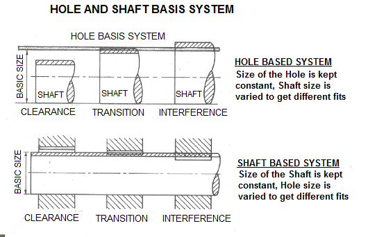
The Hole Basis System
In the hole basis system, the size of the hole remains fixed or standardized. However, the shaft’s size varies based on the type of fit desired. In essence, this system is centered on the premise that holes are more challenging to alter once manufactured compared to shafts.
Advantages of the Hole Basis System:
- Greater flexibility in shaft manufacturing.
- Simplified assembly processes.
- Reduced production costs, given the ease of modifying shafts.
- Facilitates a standardized approach to hole creation.
The Shaft Basis System
Conversely, in the shaft basis system, the shaft’s size is kept constant. Here, it’s the hole that sees variations in its dimensions to achieve the desired fit. This system finds favor when the shaft’s design or material makes alterations difficult post-production.
Shaft basis system
Advantages of the Shaft Basis System:
- Suitable for shafts that are complex or expensive to modify.
- Allows for a wide range of fits using a single shaft size.
- Simplifies the process of designing specialized shafts.
- Encourages a uniform approach to shaft manufacturing.
Choosing Between the Two: Hole and Shaft Basis System
While both systems offer their unique merits, discerning their distinctions is crucial for effective engineering.
Table: Comparing Hole and Shaft Basis Systems
| Criteria | Hole Basis System | Shaft Basis System |
|---|---|---|
| Reference Component | Hole (standardized size) | Shaft (standardized size) |
| Variable Component | Shaft (varied based on fit) | Hole (varied based on fit) |
| Primary Advantages | Simplified hole manufacturing | Specialized shaft design |
| Common Applications | Mass production, general machinery | Specialized equipment, bespoke designs |
The decision to opt for either the hole or shaft basis system hinges on several pivotal considerations:
- Nature of Production: For large-scale, generalized production, the hole basis system might be more advantageous due to its flexibility.
- Component Complexity: For shafts with intricate designs or costly materials, the shaft basis system can be more suitable.
- Cost Implications: If altering the shaft is more economical than modifying the hole, the hole basis system becomes preferable.
- Desired Fit Range: A broader range of fits with a standardized shaft pushes one towards the shaft basis system.
- Machinery Constraints: Sometimes, manufacturing constraints can dictate the choice, especially if certain machinery is better suited for hole or shaft alterations.
What Are the Different Types of Fits?
In the world of mechanical design and manufacturing, the precision with which components come together can make or break a machine’s functionality. This precision is captured in the concept of “fits.” Let’s demystify the different types of fits and dive deep into each of their unique characteristics and applications.
Different types of fits
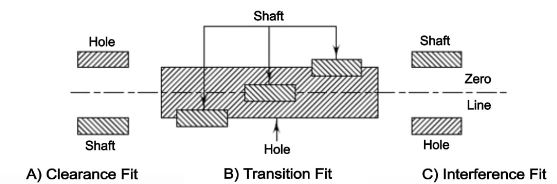
1. Clearance Fit
At the heart of machinery lies the intricate dance of parts moving in harmony. Clearance fit ensures such fluid movement. Here, the relationship between the hole and shaft is such that a gap always exists, allowing for smooth relative motion between the two. This is achieved when the largest possible diameter of the shaft is still smaller than the hole’s smallest possible diameter. As a result, there’s a ‘clearance’ or space that ensures there is no overlapping of the tolerance zones between the two components.
This fit is ideal in scenarios where ease of movement is crucial and interference isn’t desired. Think of the wheels on an axle; you wouldn’t want any restriction there, would you? However, while clearance fits are wonderful for facilitating movement, they aren’t intended for applications requiring a rigid connection.
2. Interference Fit
Contrasting the free-moving world of clearance fits, interference fits step in when the machinery demands a tight, immovable connection between components. As the name suggests, in an interference fit, the shaft interferes with the hole. This is possible because even the smallest diameter of the shaft is larger than the hole’s largest diameter. This ensures an overlap between the tolerance zones, leading to a tight-fitting that requires force during assembly.
These fits are often found in machinery where relative movement between parts can be detrimental, such as in the fitting of a gear onto a shaft. The interference provides a firm grip, ensuring the components act as one. However, this tightness also means that assembly and disassembly can be challenging, sometimes requiring special techniques like heating.
3. Transition Fit
Navigating between the realms of clearance and interference fits is the transition fit. An embodiment of versatility, this fit could lean towards clearance or interference, depending on manufacturing tolerances. When it comes to the transition fit, the shaft’s size might be almost equivalent to the hole, slightly larger, or even slightly smaller.
There’s potential for either slight movement or a touch of tightness, making this fit a jack-of-all-trades. It’s typically employed in scenarios where there’s a need for flexibility, perhaps a component that occasionally needs adjustment. While the transition fit promises adaptability, it also demands precision in manufacturing, given the tight margins it operates within.
Comparative Table: Different Types of Fits
| Criteria | Clearance Fit | Interference Fit | Transition Fit |
|---|---|---|---|
| Interference/Clearance | Always has clearance | Always has interference | Can have either, depending on tolerances |
| Characteristic | Ensured gap between parts | Tight, immovable joint | Either slight movement or slight tightness |
| Application Example | Wheels on an axle | Fitting of a gear onto a shaft | Certain bearing arrangements |
| Assembly Ease | Generally easy | Can be challenging; might need heating | Depends on exact tolerances; might need adjustments |
| Common Uses | Where movement is crucial | Where rigid connections are essential | Where flexibility in fit is beneficial |
Various Standards for Fits
In the vast expanse of machinery design and engineering, the minute details can often have the most profound impact on performance. The precision with which two components come together – often a hole and a shaft – isn’t merely a result of random choices but is guided by meticulously crafted standards. These standards play an instrumental role in ensuring that various components can come together seamlessly, irrespective of where or by whom they were manufactured. Let’s delve deep into understanding these standards and their significance.
The Need for Standards
Before we navigate the standards themselves, it’s crucial to grasp their importance. Why do we need standardized fits?
- Uniformity Across Borders: In our globalized world, a component manufactured in Germany might find its way into machinery in Japan. Standards ensure that irrespective of geographical locations, fits remain consistent.
- Reliability: With set standards, engineers and manufacturers can be confident about the expected results of their designs.
- Efficient Manufacturing: Standards streamline production processes, reducing the need for constant checks and adjustments.
- Safety: Consistency in fits reduces the chances of machinery failures which can lead to accidents.
International Standards
While several organizations worldwide set standards, the International Organization for Standardization (ISO) is widely recognized. Their system for fits, known as the ISO system, is universally adopted in various industries.
- ISO Fits: The ISO system defines fits for mating parts as per their dimensions and tolerances. It provides a comprehensive database, spanning from the smallest to the largest sizes and is based on metric units.
- Categories of Fits: ISO has categorized fits into three primary types – clearance fits, interference fits, and transition fits, each with multiple subcategories based on exact tolerances.
Standards don’t just specify the type of fit but also detail the exact tolerances allowable for that fit. Here’s a simplified representation:
Table: fits and tolerances
| Fit Type | Tolerance (Example) | Application |
|---|---|---|
| Clearance Fit | H7/g6 | Bearings that rotate on a shaft. |
| Interference Fit | H7/p6 | Pressed steel rings on a shaft. |
| Transition Fit | H7/k6 | Stepped pulleys for a drive belt. |
(Note: The above table is a simplified representation. Actual standards have a vast array of combinations, each suited for specific applications.)
CNC Machining for Precise Fits: A Step-by-Step Overview
The transition from an idea on paper to a tangible, perfectly-fitting component through CNC machining is a mesmerizing journey. Here’s a step-by-step overview of how CNC Machining ensures precision for interference fits:
Table: CNC Machining process for Precise Fits
| Step | Action | Importance |
|---|---|---|
| Step 1: Designing with CAD Software | Using Computer-Aided Design (CAD) software, engineers create a digital 3D model of the component. | Ensures the component is designed with precision, keeping in mind the requirements of interference fits. |
| Step 2: Converting Design to Machine Language | The design is converted into specific instructions through Computer-Aided Manufacturing (CAM) software. | Translates the design into a language the CNC machine understands, guiding its actions accurately. |
| Step 3: Setting Up the CNC Machine | The correct tools are loaded into the machine, and raw material (like metal or plastic) is positioned. | Ensures the machine is equipped with the right tools and material for smooth and precise production. |
| Step 4: Machine Calibration | Involves setting the machine’s zero point and configuring its speed and feed rates. | Proper calibration ensures machining occurs within the tight tolerances required for interference fits. |
| Step 5: Commencing the Machining Process | The CNC machine follows the instructions from the CAM software, cutting, drilling, or shaping the raw material. | Transforms the design into a tangible component, ensuring the final product will fit perfectly as intended. |
| Step 6: Quality Control & Inspection | Using precision measuring tools, the component is checked against the original design specifications. | Confirms that the product meets the exact requirements for the interference fit without deviations. |
| Step 7: Post-processing (If Required) | Processes like polishing, heat treatment, or coating might be applied. | Enhances the component’s durability, appearance, or fit as necessary. |
| Step 8: Assembly or Integration | Depending on its purpose, the component might be assembled into a larger system or used as a standalone component. | Ensures the component’s precision benefits the system’s overall functionality or serves its standalone purpose efficiently. |
How to Choose the Right Fit?
Selecting the right fit is crucial for any engineering and design project. The chosen fit can influence the functionality, efficiency, and lifespan of a component within a system. Understanding the various types of fits and their applications can greatly benefit the outcome of any design. Here’s a guide to help you select the most appropriate fit for your needs.
1. Determine the Application’s Requirements
- Functional Needs: Understand the functional requirements of your component. Does it need to rotate freely, slide, or be firmly fixed?
Example*:* A motor shaft that needs to rotate without resistance would require a clearance fit.
- Load Bearing: Components that bear loads, especially under dynamic conditions, often require tighter fits to distribute forces evenly.
Example: For a heavy-duty pulley system, an interference fit might be more appropriate to handle the load without slippage.
- Temperature Fluctuations: If your assembly will experience temperature changes, remember that materials expand and contract differently. This can affect the fit over time.
Example: For an engine part that heats up, a transition fit might be used to account for thermal expansion.
2. Assess Material Properties
Material hardness plays a significant role in determining the fit. Harder materials can handle tighter fits without undergoing deformation. In contrast, softer materials may get damaged or deformed with tight fits. Another consideration is the thermal expansion coefficients of materials. Materials expand and contract at different rates, and choosing a fit without this in mind could lead to malfunction under temperature fluctuations. Additionally, in environments prone to moisture or chemicals, material corrosion can alter the fit. Opting for materials that resist corrosion can help prolong the effective life of the fit.
3. Understand Tolerance and Manufacturing Capabilities
Every manufacturing process comes with a certain level of variability. Recognizing the tolerance levels associated with these processes can guide decisions about how close a fit should be. Not all fits are straightforward to achieve with every manufacturing method. For example, producing very tight interference fits might necessitate the use of advanced CNC machining techniques or specialized tooling.
4. Lifecycle and Maintenance Considerations
Considering the lifespan of a component is crucial. If a component will need frequent replacements, a fit that allows easy disassembly might be more appropriate. Similarly, for systems that require routine maintenance or inspections, it’s essential to ensure that components can be readily accessed without causing damage to them or neighboring parts.
5. Safety and Compliance
Safety should always be a priority. Some industries operate under strict safety regulations, which often dictate the types of fits permissible. Furthermore, in critical applications like aerospace or medical devices, it’s crucial to ensure that the chosen fit adheres to industry standards and certifications.
6. Consult with Experts
Engaging with professionals in the field, especially for crucial applications, is always a wise decision. Engineers or specialists can offer insights based on their expertise and might bring attention to aspects that may have been initially overlooked.
Mastering Precision with Prolean’s CNC Machining for Fits
In the realm of precision engineering, Prolean stands as a beacon of excellence, particularly when we talk about CNC machining services tailored for perfect fits. This is no small feat in an industry where micrometers can make a massive difference. Our dedication to achieving the pinnacle of precision stems from its unwavering commitment to understanding the intricate dynamics of fits in engineering applications.
Harnessing the power of advanced CNC machinery, Prolean has consistently provided solutions that cater to the diverse needs of industries. Whether it’s an interference fit demanding exacting precision or a clearance fit where allowances are a bit more forgiving, our machinery and expertise stand ready to deliver. But what truly sets us apart is their holistic approach to the process. Rather than just focusing on the machining aspect, Prolean places significant emphasis on comprehensive planning, design consultation, and post-production quality checks.
Read More:
- The Ultimate Guide to Waterproof Enclosures
- Center of Rotation: A Comprehensive Guide
- A Comprehensive Guide to Undercut Machining
- The Essential Guide to Runout in Precision Machining
- The Ultimate Guide to Workholding in CNC Machining
Conclusion
The intricate world of engineering fits is a testament to the precision and attention to detail required in modern manufacturing and design. The choice between clearance, interference, transition, and other fits can greatly influence a product’s functionality, safety, and lifespan. From understanding material properties to considering the manufacturing capabilities, numerous factors come into play. While theoretical knowledge provides a foundation, the practical insights from experts in the field further enhance decision-making.
As industries advance and technologies like CNC machining evolve, the importance of selecting the appropriate fit becomes even more pronounced. Ultimately, the right fit not only ensures seamless integration of components but also upholds the integrity and reliability of the entire system.
FAQs
What is interference fitting?
Interference fitting is a method where a component (typically a shaft) is made slightly larger than the receiving component (usually a hole) ensuring a tight fit.
Why are engineering fits important?
They ensure machine components come together perfectly, ensuring optimal function, safety, and longevity.
What’s the difference between hole and shaft basis systems?
In the hole basis system, the hole size remains constant. In the shaft basis system, the shaft size remains consistent.
How has CNC machining impacted engineering fits?
CNC machining offers precision, ensuring that the desired fit, especially interference fits, are achieved flawlessly.
Are there standards for engineering fits?
Yes, organizations like ISO set global standards for fits to maintain consistency across industries.
When is an interference fit used?
Interference fits are ideal for situations where a permanent and tight connection between components is required.

0 Comments