In custom sheet metal fabrication, tolerances determine whether a part fits seamlessly. Engineers and Designers must account for balancing dimensional changes in the product throughout the manufacturing process. The part may lack quality and performance if a variation range is too wide. Conversely, you may need to impose tighter tolerances if the range is too narrow. It not only leads to higher costs but may be challenging to obtain.
If you are contemplating sheet metal thickness tolerance, this guide is for you. So, give it a read, as it covers all the details about custom sheet metal tolerances and how you can achieve them.
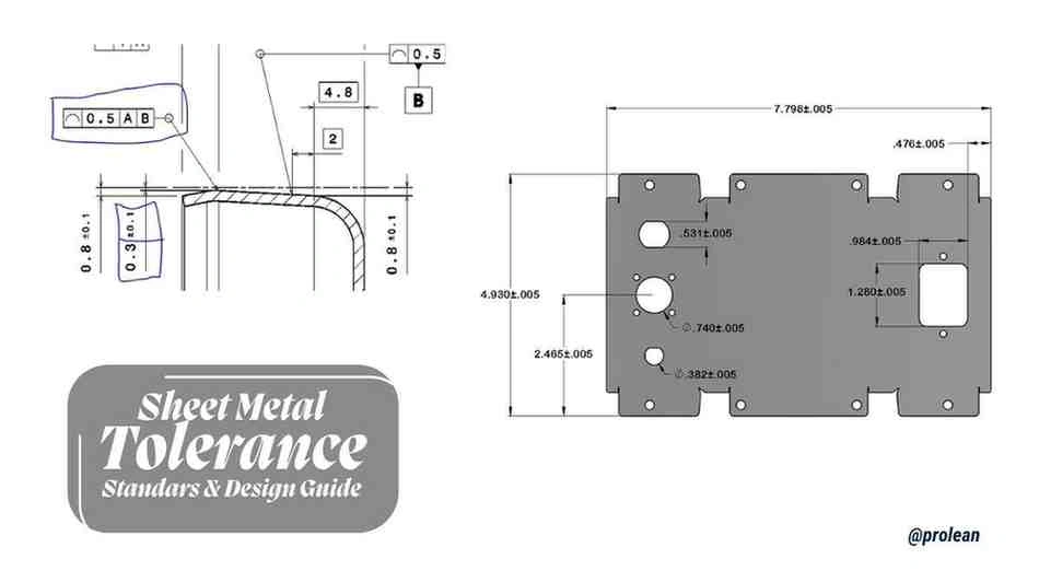
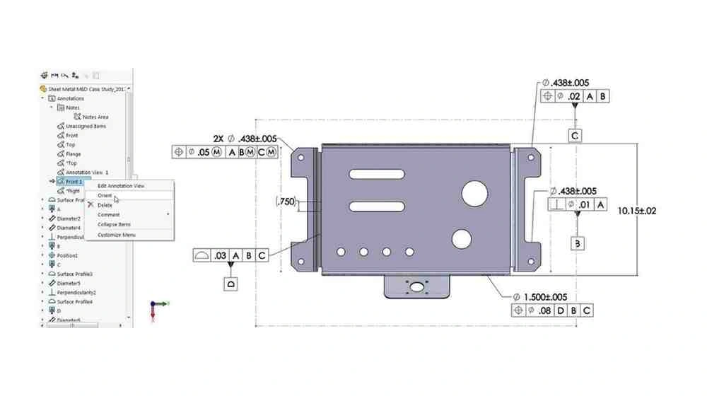
What Is Sheet Metal Tolerance?
Sheet Metal Bending Tolerances (Bend To Bend)
Dimensional tolerances should be set carefully. As mentioned before, tolerances are the permissible limits of measurement deviations in a part. In precision sheet metal fabrication, tolerances help shape parts that fit and function properly without compromising the quality.
Tighter tolerances are relatively expensive as these demand more precise manufacturing techniques. For custom sheet metal fabrication, tolerances typically range from ±0.005″ for high precision to ±0.060″ for less critical parts. These typically depend on the thickness and type of materials.
Why Are Sheet Metal Tolerances Important?
Importance of Sheet Metal Tolerance
Many factors affect how tolerances are set based on the type of material, their thickness, and the method of processing. Even the most minute details, like the texture, hardness, and even the metal purity, can impact the part dimensions.
Thicker sheets have large tolerances due to higher rigidity. The rigidity associated with thicker sheets permits a large margin of error. Tighter tolerances in thinner sheets constrain deformation. Tolerance changes during fabrication are dependent on process control, which assures precise dimensions and fit.
Moreover, thicker sheets are stronger but negatively affect design freedom. Thinner, lighter sheets are easier to bend. Assembly issues may arise with inappropriate thickness choices.
Different materials have different requirements for tolerances. For example:
- Aluminium alloys are softer and typically have a tolerance of up to ±0.1mm, depending on the processing method.
- Stainless steel, being harder, can achieve tighter tolerances of ±0.05mm to ±0.15mm, depending on the fabrication technique.
- Carbon steel’s tolerance typically ranges from ±0.1mm to ±0.2mm based on thickness and processing.
Table 1: Typical metric manufacturing tolerance ranges.
|
Material Thickness (mm) |
Tolerance Range (mm) |
|
0.5 – 1.0 |
±0.1 |
|
1.0 – 2.0 |
±0.15 |
|
2.0 – 3.0 |
±0.2 |
|
3.0 – 5.0 |
±0.25 |
|
5.0 – 8.0 |
±0.3 |
Try Prolean Now!
What Factors Affect Sheet Metal Bending Tolerances?
Your sheet metal fabrication tolerances are influenced by several technical factors. These include:
Materials Specifications, Types, and Thickness
Material Specifications Impact on Tolerance
Material type and thicknesses of sheet metal have a significant impact on allowable tolerances. Generally, thicker metal sheets comprise flexible tolerance levels. In reverse, thinner sheets have tighter tolerances.
Dimensional tolerances achievable for stainless steels and tool steels are rigid and stable in dimension. These tolerances are much tighter than those for mild steel and aluminum alloys.
For instance, stainless steel alloys can achieve tolerances of ±0.005,” whereas aluminium alloys would require ±0.010” due to their high coefficients of thermal expansion and softness properties.
Cutting and Forming Techniques
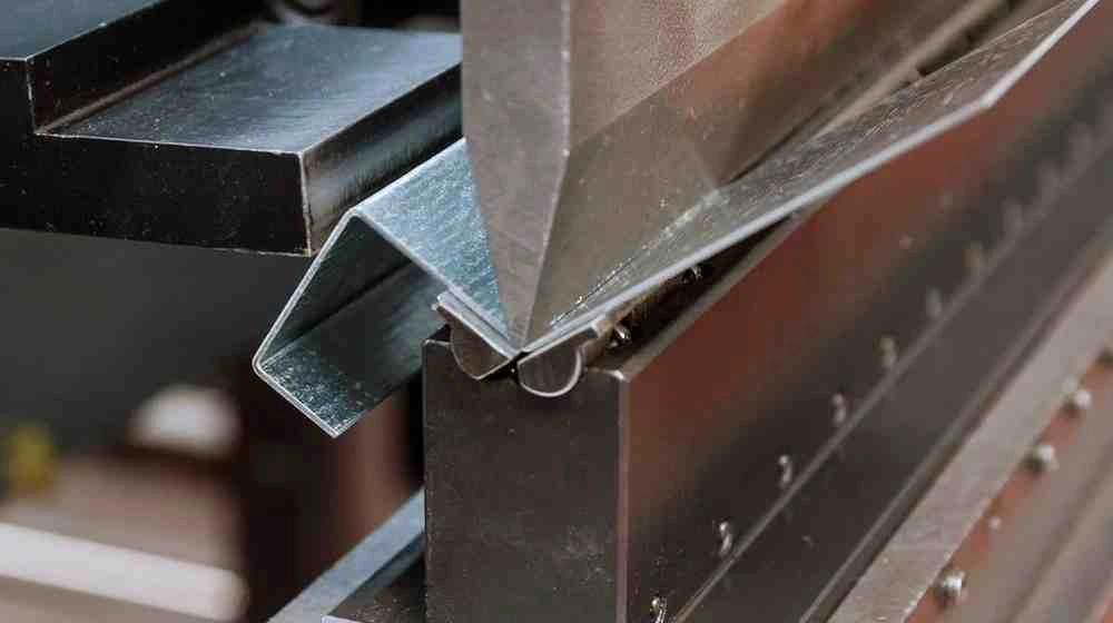
Sheet Metal Forming
Different machining techniques provide various degrees of accuracy. Laser cutting is one of the most accurate methods and can achieve tolerances as tight as ±0.005″ for thin materials, but generally, ±0.010″ to ±0.015″ is more typical. Plasma cutting has a larger tolerance range, typically ±0.030″ to ±0.060″, while waterjet cutting can achieve tolerances in the range of ±0.005″ to ±0.020.
In addition, forming techniques like bending, stamping, and deep drawing entail some additional variables. These include K-factor, springback, and the progress of deformation. Furthermore, the number of bend angles and mechanical properties tend to increase the deviations made from the final expected dimensions. (Get more insights on sheet metal surface finishes.)
Tool and Die Precision
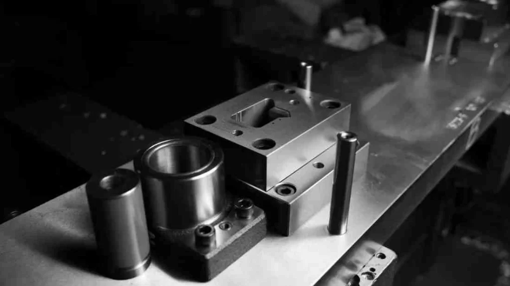
Sheet Metal Tooling
The tool state used in the part fabrication process also influences your part tolerance. For example, precise ground die,s and high-quality carbide tools will give tighter tolerances in the long run. On the other hand, old tools, if not maintained well, can introduce paradoxical errors. Generally, reliable steel dies can be used to gain tighter tolerances.
Mechanical Accuracy and Calibration
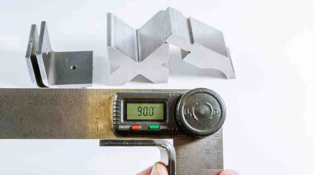
Material Thickness Measurement
The tolerance limits are directly influenced by the capabilities of the machinery. Let’s take an example: an automated press brake and CNC machining centers can achieve an accuracy of ±0.001” when properly calibrated. On the other side, your part dimensions can badly impact more than expected due to minor misalignments. Like a minimal of 0.1° error on a bending machine. To meet near-exact tolerances, you need to regularly inspect your machines in terms of calibration and precise programming.
Operational Skills & Expertise
Consistent accuracy in tolerances also depends on the fabricator’s experience. Skilled machinists always set optimum machine parameters. They can respond earlier to machine errors and carry out preventative checks to mitigate the variation. The lack of precision is further counteracted by process control, real-time control, and automatic control measurement systems.
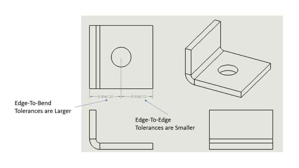
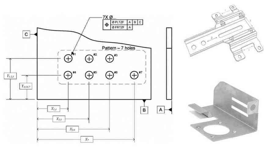
Geometric Constraints and the Complexity of Design
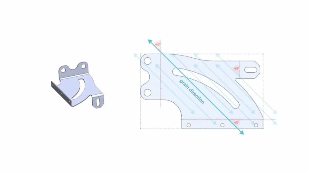
Sheet Metal Complicated Design Part
Simple parts with straight cuts and uniform thicknesses tend to permit tighter tolerances of ±0.010”. On the other side, complicated geometries with multi-bent and deep drawing have a larger variation of tolerances of ±0.030”. These tolerances may lead to a tolerance stacking due to factors like cut distance to bend, placement of holes, and asymmetrical designs.
Material Expansion & Dimensional Stability
Usually, soft materials (particularly aluminum) tend to expand by heat. Even a slight change can affect your part precision. For example, aluminum has a higher thermal expansion coefficient (23 × 10⁻⁶/°C). It undergoes huge size alterations than stainless steel (10-12 × 10⁻⁶/°C), which is relatively harder. Therefore, these changes must be accounted for and compensated during fabrication to achieve tight tolerances.
Try Prolean Now!
Component Sizes for Sheet Metal Parts
Size Distribution of Sheet Metal Part
Here are the minimum and maximum dimensions/sizes for sheet metal types. Please note that these dimensions may vary based on equipment and process capabilities.
Table 02: Minimum and maximum part dimensions.
|
Type |
Inches (in.) |
Millimeters (mm) |
|
Min. Dimensions |
||
|
Flat Part |
0.250 x 0.250 |
6.35 x 6.35 |
|
Formed Part |
0.500 x 0.500 |
12.7 x 12.7 |
|
Max. Dimensions |
||
|
Part Size |
39 x 47 |
990.6 x 1,193.8 |
|
Bend Length |
47 |
1,193.8 |
Sheet Metal Tolerances Industry Standard

Sheet Metal Tolerance Standards
Sheet metal tolerance specifications are unified by definitions from various international standards. The standards have allowed all industrial production sectors to create their quality control systems. Here are a few common standards.
ISO 2768
ISO 2768 specifies general sheet metal tolerances. It groups tolerance classifications under fine (f), medium (m), coarse (c), and very coarse (v). It provides specifications for measuring linear and angular units. Besides, it sets requirements regarding geometric imprecision standards.
ASME Y14.5
ASME Y14.5 is an American standard. Usually, engineering drawing dimensioning and tolerancing standard formats are defined by it. It specifies geometric requirements and GD&T symbols. Moreover, it encompasses a selection of 14 geometric parameters that exist with 05 tolerance regions. ASME Y14.5 is primarily practiced in aerospace and automobile manufacturing settings. Design ambiguities and errors are reduced, and part interchangeability gets validated through its implementation.
DIN 2768
The Deutsches Institut für Normung e.V. is a German standard. It dictates linear dimensions, angular positions, and fundamental geometric constructs. The standard adopts tolerance categories that exactly mirror those found in ISO 2768. DIN 2768 finds its application primarily in machinery and electronics products.
JIS B0405
JIS B0405 is a Japanese Standard. It includes details about straight-line measurement tolerances. It specifies distribution patterns between intercomponent features. Usually, JIS BO405 is followed in automobile and electronics companies. JIS B0405 serves as a guide that allows manufacturers to produce premium-quality items at affordable prices.
Sheet Metal Design Guidelines
When your design is substandard, the chances are higher for getting weak components, production vulnerabilities, and higher manufacturing expenses. To avoid design error, choose the right material and manufacturing method. (Here, in our guide on sheet metal design guidelines, we mentioned various aspects of designing critical part features.)
Bend and Relief Radius
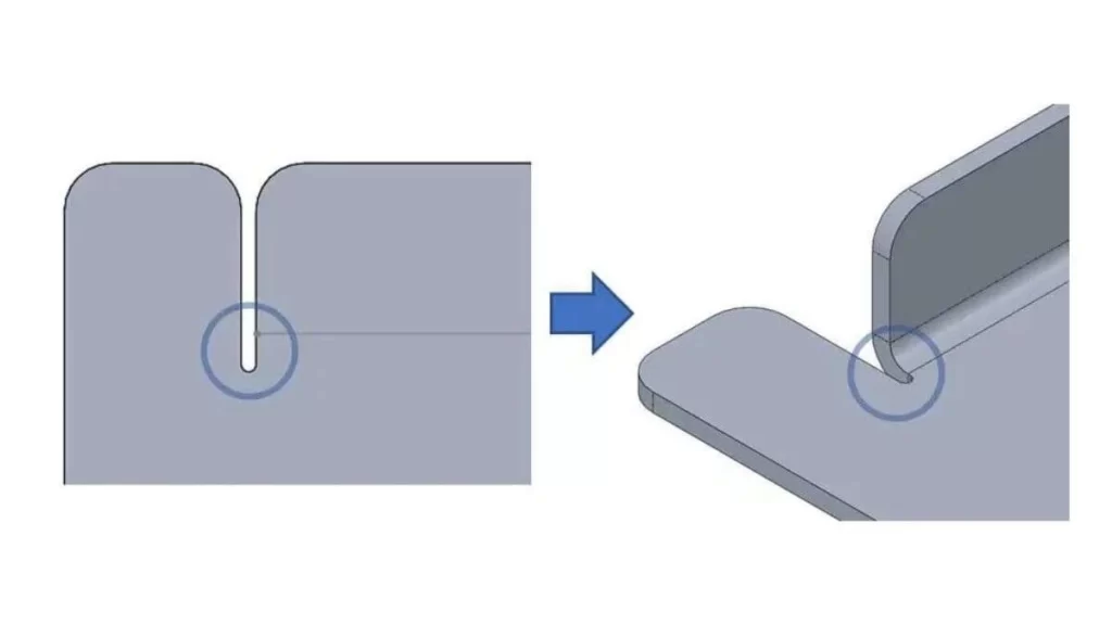
Bend Relief
The bend and relief radius specify how strong and tolerant a part will become. The minimum inside circular shape for bent sheet metal structures corresponds to the bend radius specification. Small relief radius cutouts avoid bending tears by performing the essential function at their locations.
Key Guidelines:
- The material must have a thickness equal to 1 to 1.5 times the smallest bend radius value.
- The fabricator should create matching bending radii throughout the process.
- When handling brittle substances, one needs to alter bending radius distances to prevent material breakage.
- To reduce stress, the relief radius should be set at twice or 1.5 times the material thickness.
Offset Bends
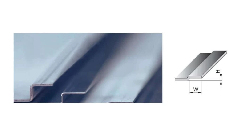
Offset Bend Depiction
The material forms a step feature through multiple bending directions that occur in opposite directions. Multiple bending processes strengthen components while reducing their vulnerable areas.
Key Considerations:
- There must be at least twice the material thickness between two parallel planes.
- The fabrication process becomes convenient when offset bend angles stay below 90 degrees while designing smaller components.
Sheet Metal Curls
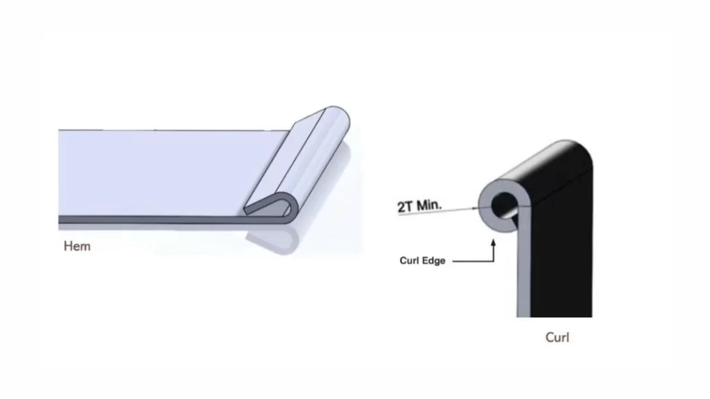
Sheet Metal Curling
Circular rolling techniques increase the strength of sheet material edges. Because they are formed into curved shapes. Introducing sheet metal curls will improve your part safety.
Key Guidelines:
- An outer curvature needs to be at least double the sheet material thickness.
- Holes should be applied to sheets at a distance. These must match twice the material’s thickness with the curl radius to protect the material’s integrity.
Final Thoughts
The blog has covered a vast amount of information on Sheet Metal Tolerances. We provide process, design considerations, and established industry standards. Design manufacturers need to adhere to strict tolerance standards for complex components to improve the precision and performance of parts. As you know, sheet metal fabrication involves multiple procedures. These include cutting, bending, stamping, and punching operations. So, calibrated machines paired with skilled fabricators can help produce the desired tolerances. We understand it’s a bit of a daunting task, but don’t fret.
ProleanTech operates processing facilities that house advanced CNC press brakes, shearing machines, and fiber laser cutters to meet our customers’ requirements. Our extensive manufacturing experience allows us to deliver precise sheet metal service in menial turnover.
Need precise sheet metal fabrication with guaranteed tolerances? Contact our experts today for a free consultation and quote. Let’s bring your designs to life with accuracy and efficiency!
FAQ’s
Q1: What is the tolerance for sheet metal?
Sheet metal tolerances normally depend on the type of material, sheet thickness, and production process. Generic tolerances are usually set within ±0.1 mm to ±0.5 mm. For a more precise and closer one, you may need additional machining processes for quality control.
Q2: What is the ISO standard for sheet metal tolerances?
ISO standards specify the limits for bending, cutting, and assembly. For example, ISO 2768 provides general tolerances for sheet metal parts. ISO 9013 applies to laser-cut parts/components.
Q3: How do custom sheet metal fabrication services handle tolerances?
CNC machining, laser cutting, and precision bending tools are used for custom sheet metal fabrication services. To ensure quality, you need to have strict inspections and accurate quality checks so that standards can be met.
Q4: Can sheet metal tolerances be adjusted for different applications?
Yes, the permissible deviation of dimensional measurements depends on the part’s functional use, material type, and industrial standards. Usually, critical automotive and aerospace parts need precise tolerances. Whereas general-use parts receive adaptable tolerances.
Q5: How can Proleantech ensure that sheet metal parts meet the required tolerances?
Proleantech faculty uses advanced CNC machines and laser cutting for high-precision applications. Our strict quality control measures, including in-house inspections and testing, guarantee that your parts meet exact tolerances and standards.
0 Comments