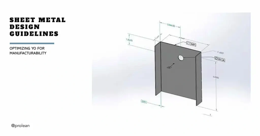
Sheet metal fabrication is a complex manufacturing process that includes cutting, bending, hole punching, embossing, and many other forming operations. As the parts have more features, the complexity of the design also increases. Therefore, you must consider the sheet metal design guidelines to ensure manufacturability.
The sheet metal design guidelines include dimensioning, tolerances, positioning, symbols, and other features in the design. In the design, you must incorporate various rules for bending, punching, cutting, and other operations.
Furthermore, explore the design guidelines for different sheet metal fabrication techniques to optimize your design for manufacturability.
Sheet Metal Bending Rules
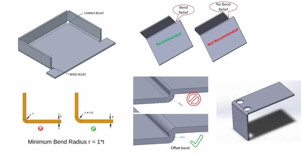
Features of sheet metal bending design
Bending is typically done with a press brake mechanism in a suitable die size. If your sheet metal manufacturing designs has bends, follow the following design rules.
1. Maintain a uniform bend radius, the minimum radius at which a material can be bent without causing damage, cracking, or deforming.
2. The minimum bending radius you should consider while designing is at least equal to the thickness of the worksheet.
Min. bend radius ( r. min) ≥ thickness (t)
3. Bend reliefs are the small cuts or notches near the bend area, which prevent material tearing and distortion. Include bend reliefs if you have long straight bend lines in sheet metal design.
Relief width= 0.5 x thickness (t)
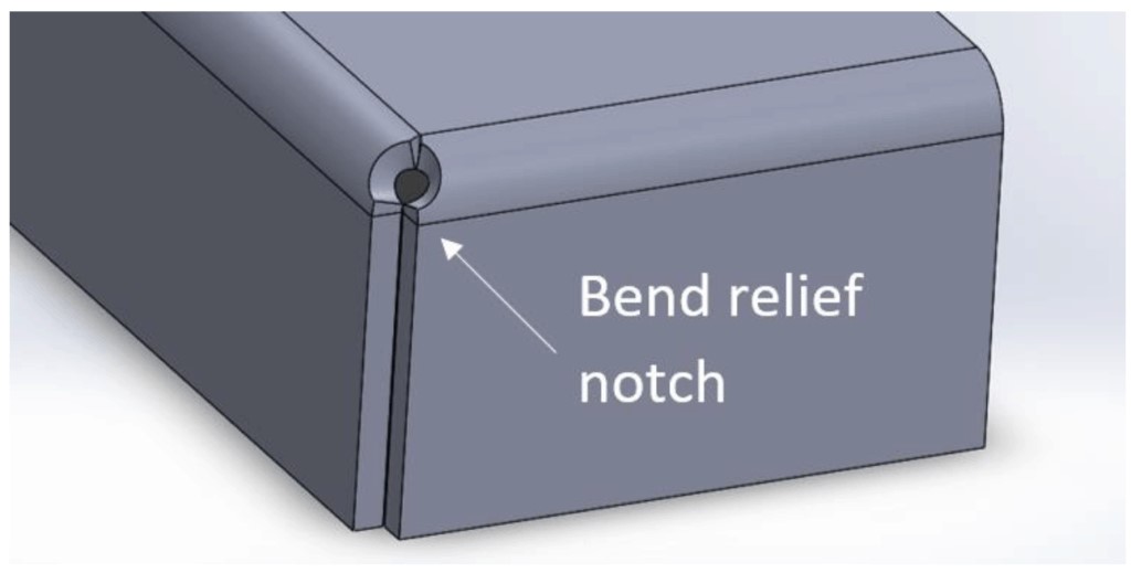
Bend relief notch
4. A consistent bend orientation is important for ease of fabrication.
5. The K-factor of your bending design should be chosen from a K-factor chart based on the material type, bend angle, and operation. It typically ranges from 0.25 to 0.50.
6. If your design has offset bends ( Z-shaped), Maintain flange length (on Both Sides)= 3 x thickness(t)
7. The height of the bend can not be too low or too high, otherwise it results in poor deformation.
Bend height (h)= 2 x thickness(t) + bend radius (r)
8. Does your design have a hole near the bending lines? If yes, you need to maintain a certain spacing between them.
Bend to hole = 2.5 x thickness(t) + bend radius (r)
Sheet Metal Design Guidelines for Hole and Slot Features
Holes and slots are critical features in sheet metal fabrication, they are created with punching, laser cutting, drilling, and other appropriate technologies. The following are some design rules for slots and holes.
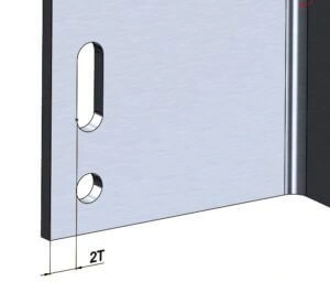
Hole and slot in sheet metal design
1. The minimum hole diameter should be ( Dmin) ≥ the thickness of the sheet metal ( at least equal to sheet thickness).
2. Proper spacing between the two holes center in a sheet panel avoids cracking and material tearing.
Spacing= 2 x thickness (t) + bend radius(r)
3. The minimum distance between the hole or slot and the edge of the sheet should be three times of sheet thickness.
Min. Edge-to-hole distance= 3 x thickness
4. If the custom sheet metal fabrication design has semi-pierced or extruded holes, the distance from the edge or bend to them should be three times of sheet thickness.
Try Prolean Now!
Notches, Tabs, and Fillets Features
Notches are the small cutout sections and tabs are the protruding features on the sheet metal. Consequently, fillets refer to a smooth and rounded transition between two surfaces or along an edge.
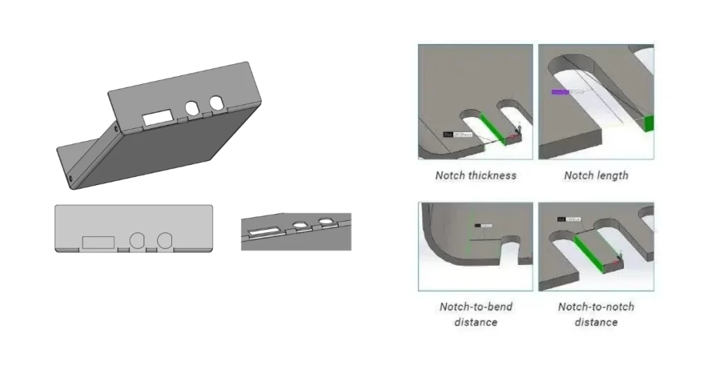
Sheet metal notches and tabs design
- Maximum notch length= 5 x sheet thickness(t)
- V-notch length= 2 x notch width (w)
- Minimum corner radius= 0.5 x sheet thickness(t)
- Maximum tab width= 2 x sheet thickness(t)
- Tab depth ≤ 5 x tab width(w)
- Fillet size 0.5 x sheet thickness (t)
- Min. distance between two tabs= sheet thickness (t)
- Min. distance between two notches= 2x sheet thickness (t)
Hems and Curls Features
Hems are the folded edges back onto themselves and curls are the small hollow rolling edges. Both of these features avoid the sharp edges of sheet metal and make the parts easier to handle.
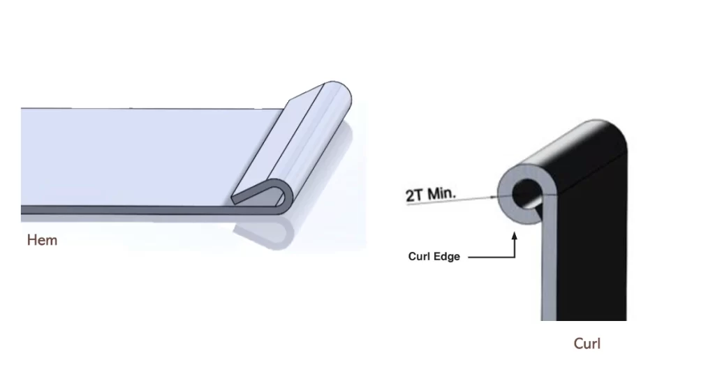
Hem and curl features
- Min. Hem diameter (Inside)= sheet thickness (t)
- Return hem length= 6 x sheet thickness (t)
- Min. Distance between hem/curls to bend = 5 x sheet thickness (t) + bend radius + hem radius
- Min. Curls radius(outside)= 2x sheet thickness (t)
- Min. Curl to bend distance= curl radius + 6 x sheet thickness (t)
CAM Software for Sheet Metal Design Optimization
Computer-aided manufacturing (CAM) software seamlessly transitions from design to production by simulating the fabrication processes. It allows for easy modifications to optimize the designs.
CAM software ensures that each design is both functional and cost-effective. So, sheet metal manufacturers can save time and resources during the fabrication.
Selection of Surface Finishing for Sheet Metal Designs
If you are using CAD software, they must include the roughness level (Ra) and different sheet metal surface finishes options to see how the production will look after the treatment. On the other hand, you must specify the finishing technique and required Ra value on the drawing.
The appearance(colors) is also essential for custom sheet metal projects. You can apply different colors in CAD designs to see the appearance.
Below are the drawing symbols for surface roughness;
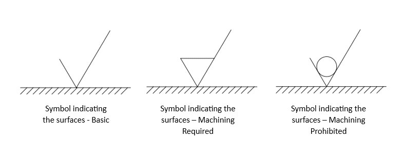
Surface roughness symbols
Furthermore, the common techniques for sheet metal surface finishing are polishing, powder coating, electroplating, metal coating, and anodizing.
Try Prolean Now!
Summing Up
The precision, accuracy, and speed of sheet metal manufacturing depend on the design specifications. Therefore, optimizing your sheet metal drawing according to the design guidelines is essential. It ensures manufacturability and high-quality production.
At ProleanTech, our design engineers help to optimize your drawing according to the sheet metal design guidelines. So, we can streamline the fabrication process and reduce material waste and cost. Our sheet metal fabrication service includes bending, stamping, welding, punching, blanking, deep drawing, embossing, etc. You can leverage advanced technology and sheet metal experience to achieve the parts that perfectly fit your requirements.
FAQs
What are the best tools for sheet metal designs?
You can use Autodesk Inventor, SolidWorks, Siemens NX, etc. to create a computer-aid design(CAD) of sheet metal parts and products. They also help to transition the design into the production phase.
What is meant by sheet metal design guidelines and manufacturability?
Sheet metal design guidelines focus on optimizing designs for ease of manufacturing by considering material thickness, bend radius, tolerances, tooling, etc. It is essential to follow to reduce cost and fabrication errors.
How to design good sheet metal parts?
There are some basic guidelines for sheet metal design, maintain a consistent thickness, use suitable bend radii, and minimize the intricate features.

Wow wonderful format to describe the design rules! Thanks I was looking for design guidelines for my enclosure project !