You may have noticed bent tubular structures in the exhaust of your car or motorcycle, which is a typical application of tube and pipe bending. The bending process can shape tubes made of stainless steel, carbon steel, iron, aluminum, copper, brass, and several other materials into the desired form.
There are several techniques in tube bending that you can choose based on the required number of bends and other design specifications. A high level of customization is available regarding size, geometry, and precision.
The upcoming sections will elaborate on the different tube and pipe bending methods, tube bending tooling, design considerations, applications, and related calculations.
Fundamentals of Tube and Pipe Bending
In the context of fabrication procedures, pipe bending and tube bending are often used interchangeably; the primary difference lies in the level of precision and tooling control. Tube bending involves tighter tolerances and precise tooling, whereas pipe focuses on larger radii and flow rather than tolerances.
Basics of tube bending
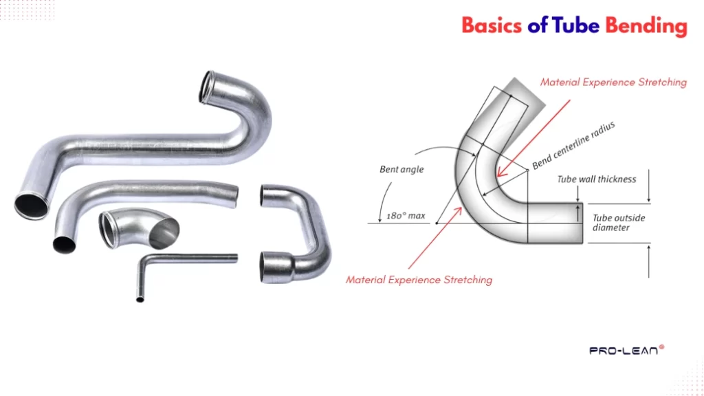
A tube or a pipe is a hollow cylindrical piece defined by centerline radius, nominal diameter, wall thickness, and length. It has extensive uses in fluid control systems and sometimes as structural components.
The deformation happens at the tube wall. When the bending force is applied, the material near the inside wall goes through compression, and the outside surface experiences stretching. This stretching & compression affects the inside and outside bend radius.
Designers and fabricators consider a centerline (neutral axis) as a basis for drawing, tooling, and forming operations. You can see this illustration in the schematic diagram below.
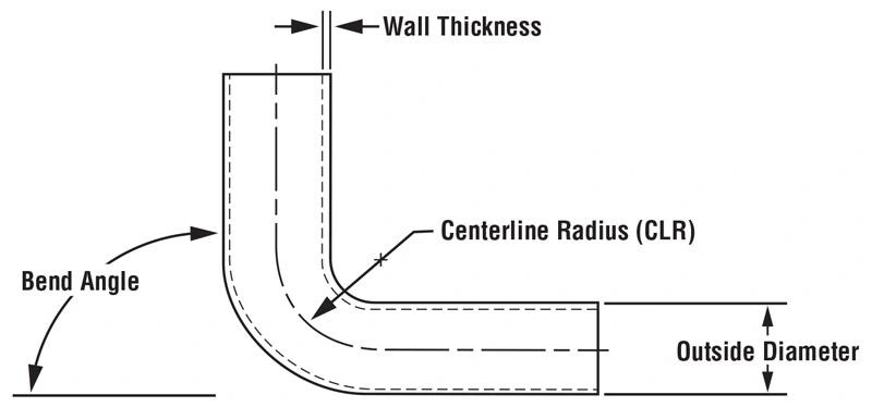
Bending illustration
Bending variables (shown in the diagram above) help determine how the material will behave during deformation and potential dimensional deviations. For instance, a slight error in thickness compromises the accuracy of the bent radius, influencing the performance & fitting.
“If you want to read about bent sheet metal parts also, read a detailed article on Sheet metal bending here.”
Try Prolean Now!
Types of Tube Bending Methods
For tube and pipe bending, there are four different methods: Roll Bending, Rotary Draw Bending, Compression Bending, and Press Bending. Each of these methods differs in bending procedures and has distinct application preferences.
Let’s discuss them briefly.
Rotary Draw Bending
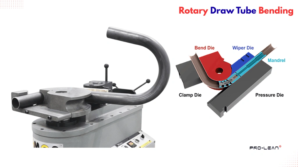
Rotary draw tube bending
This method involves a pressure die, a clamp die, a rotary bend die, a wiper die, and a mandrel. The deformation force is applied through the rotation of the rotary bend die.
Tube bending toolings for rotary draw methods are:
- Clamp Die: It holds the tube so the bend die can draw the tube to bend around the contour
- Wiper Die: It is used to compensate for the gap between the bend and the pressure die, allowing the tube to receive better support while drawing.
- Bend Die: It defines the bend profile; the tube is drawn around this.
- Pressure die: It supports the outer surface, and the die moves along with the bent line as the rotating bent die draws the tube.
- Mandrel: A solid support from inside the tube/pipe to control wall thickness.
Rotary draw bending is precise and repeatable; it is typically used for hydraulic lines, roll cages, instrument tubing, fuel lines in cars & motorcycles, and handrails.
Press Bending

Tube press bending
Press bending, or Ram bending, involves pressing stationary tubes or pipes against a movable roller to achieve the desired bend profile. It is a simple process that does not give greater control over shape & complexity, but is easier and cost-effective to set up.
You can choose this method if the design does not have complex tubing profiles and tight tolerances are not necessary; rather, if you are looking for cost-effective, straightforward solutions—for example, square tube bending and thick & heavy bending.
Roll Bending 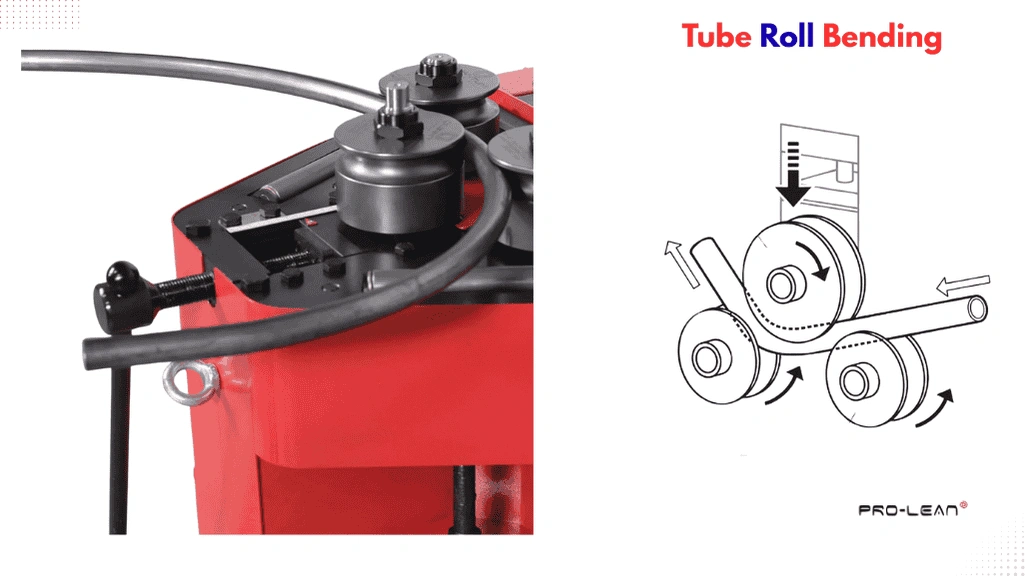
Tube roll bending
It can bend tubes and pipes with larger bending radii, useful in heavy fabrication. The setup involves three mechanical rollers assembled in a pyramid-like orientation. Meanwhile, the bending radius can be fixed by adjusting their positions. As the tube is fed between the top and bottom two rollers, the top roller provides pressure to the tube, and the bottom two rollers provide support.
Choose the roll-bending method when you need long sweeping curves with large bending radii—for instance, HVAC ducting, architectural structures, and frames for a ship hull.
Compression Bending

Tube compression bending
One end of a circular tube or pipe is fixed with a stationary die and clamp, whereas a compression die pushes the tube towards the stationary die from the other end, forming the desired bent angle & radius. This method is typically preferred when the centerline radius is greater than three times the outside diameter.
Compression bending is suitable for simple bending geometries and is cost-effective for high volumes—for instance, simple handrails, furniture frames, and electrical conduits.
Try Prolean Now!
Considerations for Tube Bending Tooling
Tooling directly impacts the quality, accuracy, costing, and efficiency of the bending process. A minor mistake in dies or other tooling accessories can cause defects like wall thickening, wrinkling, local distortion, and even material failure. This is especially critical in the rotary draw process.
The following are the key tooling considerations for efficient, accurate, and defect-free tube bending.
- Mandrel Hardness: Choose mandrel material and hardness level based on tube material; soft mandrel for hard tubes and vice versa.
- Radial Growth: For hard materials, set larger bend radii, typically greater than three times the outer diameter. It helps tooling to compensate for radial growth-related issues.
- Wiper Die: Ensure there is no wear in the contact point of the wiper die and position it at a slight angle relative to the workpiece.
- Clamp Die: A Shorter clamp die can cause cracks, so its length should be three times the tube outer diameter
- Lubrication: Use non-petroleum synthetic lubricants in the gap between the mandrel and the tube inner surface. It reduces friction during bending and also prevents galling.
Tube Bending Calculations
Similar to sheet metal bending calculation, tube bending requires several similar calculations, such as k-factor, bend allowance, springback, and other variables.
Let’s look at the major tube bending formula and major calculations.
Springback & K-factor
Springback is the deviation from the bent line/profile after the bending force is released, due to internal stress and the elastic properties of the material. Therefore, consider an additional 2°–10° bent angle for compensation, depending on material type, tube thickness, and other variables. You can refer to the springback bending tables.
Additionally, the K-factor can be calculated by the given formula: distance from inside tube surface to neutral axis divided by thickness (d/t).
Inside and Outside Radius
The inside radius is the distance between the inner surface of the tube to bend the center. It impacts the compressive strain, and a smaller inside radius can cause material buckling. On the other hand, the outside radius is measured up to the outer surface of the tube.
The tube bending formulas for inside and outside radius are given below.
Inside Radius (Ri)= Centerline Radius(Rc)- Thickness (t)2
Outside Radius(Ro)= Centerline Radius(Rc) + Thickness (t)2
Bend Allowance
You first need to determine the center line radius before the bend allowance calculation. In tube & pipe bending, the centerline-arc approach is preferred, and mid-wall is taken as the reference.
Centerlinee Radius(Rc)= Inside radius (Ri) + Thickness (t)2
Bend Allowance(BA)= π180 x Rc
Flat Centerline Length= L1 +L2 + BA ( L1 and L2 are the length of two tube legs)
Elongation at Outer Surface
Material at the outer surface stretches during tube bending, but what is the exact elongation %? It can be calculated with the given formula:
% Elongation (E)= t/2Rc x 100
How to Bend Steel Tubing?
Steel is one of the common material choices in tubing applications because of its corrosion resistance, durability, and balance of strength and formability. You can bend steel tubes by the methods discussed above. However, rotary bending is the most common choice.
For steel tube bending tooling, choose dies made with hardened tool steels. Subsequently, alloy steel or aluminum bronze for mandrels. Furthermore, consider steel grade, wall thickness, and bendability when working with large radii.
Applications of Tube and Pipe Bending
Tube and Pipe bent parts and products are used across the industries, from home appliances to construction and hydraulic machinery. It allows the fabrication of custom tubing for smooth fluid flow and rigid structures.
Next, let’s look at the tube and pipe bending applications in automotive, construction,
Automotive
- Benefits: Smooth flow paths, durable joints, lightweight, and minimal vibration.
- Examples: Exhaust downpipes, fuel and hydraulic lines, chassis sub-frames, and steering column.
Oil & Gas
- Benefits: Tube bending supports compact designs with minimal weld joints.
- Examples: Feed pipes for refinery and pressure-vessel connections
Industrial HVAC
- Benefits: Easy fittings, efficient air flow, and low maintenance requirements.
- Examples: Refrigerant supply tubes, distribution lines, coil piping.
Medical
- Benefits: High precision, unaffected internal surfaces, no risk of leakage from bending, minimal contamination risk.
- Examples: Instrument tubing, fluid lines for diagnostic equipment, frame for medical carts & furniture.
Architectural & Construction
- Benefits: High mechanical strength, rigid structures, and support for precise curvatures.
- Examples: Handrails, aesthetic facades, structural tubing components.
Read more: Sheet Metal Bending Techniques
Summing Up
Overall, tube and pipe bending is a critical process in manufacturing structural elements and fluid flow systems. Using the right type of technique, you can form complex tubing structures having multiple bends. Rotary draw can be ideal for precise multi-bend tubing, whereas ram/compression bending is best for bending metal tubes with simple geometries and a smaller number of bends.
You must consider several tooling factors and bending calculations to avoid wall thinning, springback inaccuracy, and wrinkling. If you are looking for high-quality tube and sheet metal bending service, ProleanTech provides comprehensive solutions, covering DFM feedback, Finite element analysis (FEA), Tooling, CNC bending, assembly, and Post-processing.
0 Comments