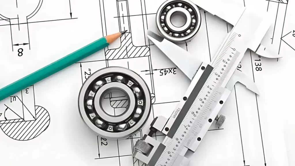
In precision manufacturing, tolerance and allowance are the foundation for producing reliable and functional parts.
Tolerance defines how much a part’s size can vary, while allowance is the planned difference between two mating components. Both directly affect fit, performance, and production costs.
At ProleanTech – Your Cutom Parts Manufacturing Partner, we specialize in applying the right tolerance and allowance strategies for CNC machining and custom part production.
With a team of experienced engineers and advanced tools, we help businesses achieve accurate, cost-effective, and quality-driven results—no matter the complexity of their designs.
This guide unpacks tolerance in engineering, what allowance means in CNC, how both are used in engineering drawings, and why they matter to your business success.
Must Read: CNC Machining Process Explained
What are Tolerances in Engineering?
Tolerance in engineering is a total permissible variation from nominal size on CNC parts.
In simple terms, tolerance is the maximum acceptable deviation from the nominal dimension of a part. A shaft labeled 20 mm ±0.05 mm means that it is acceptable if between 19.95 mm and 20.05 mm. This prevents extremely strict standards that increase the cost and fits very little which causes failures.
- Why it matters: helps machines to run frequent parts
- It also controls interchangeability and guarantees quality in batches.
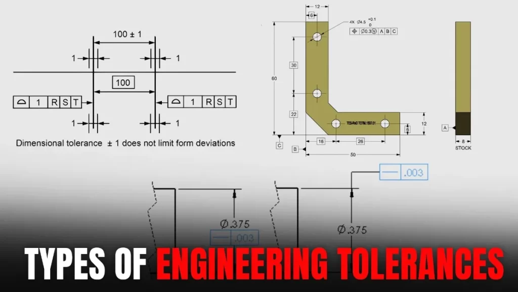
Types of Engineering Tolerances
Engineering tolerance comes in different forms, depending on what aspect of a part you want to control— shape, size, or location. Each type part fit, plays a specific role in ensuring tasks, and performs as an intention.
Below are the main types of tolerance used in engineering and manufacturing.
Types of Tolerances
1. Dimension tolerance
It controls linear shapes such as length, width and diameter. For example, a 10 mm hole may have tolerance of +0.02/–0.00 mm.
2. General tolerance
This tolerance applies when the nuances are not expanded on the picture. Standards (eg ISO 2768) define the default range based on size category.
3. Geometric dimensions and tolerant (GD&t)
GD&T adds control to size, orientation, location and runout.
Why Tolerance Is Vital in Manufacturing?
Proper tolerance in engineering drawing ensures that the parts get the design intentions and work together. It drives:
- Interchangeability — Parts also fit with different batches.
- Cost Control — Excessive tight tolerance that connects machining time is avoided.
- Quality assurance — reduces scrap and warranty failures.
Try Prolean Now!
Standard Tolerancing Strategies in Drawings
The strategy of tolerance in engineering drawings defines how the acceptable variation is presented in part dimensions. The goal is to clarify the information for mechanics and inspectors, ensuring that parts are produced within acceptable boundaries.
Two of the most commonly used strategies are direct limits and plus and minus tolerances.
1. Direct Limits
Engineering Tolerances and Direct Limits
Direct limits tolerance clearly explain the minimum and maximum allowable sizes without showing the base dimensions.
For example, a shaft can be labeled as 26.60–26.90 mm. This method saves the space and avoid confusion when interpreting the size range. It is widely used due to its simplicity.
However, it does not show a nominal (middle) value, which may be required during the quality check or procedure plan. Nevertheless, direct boundaries are particularly helpful in tight production programs where clarity and quick reference are preferences.
2. Plus and Minus Tolerances
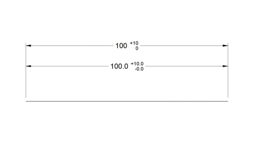
Plus/Minus Dimensional Tolerances
Plus and minus tolerance shows a base size with the upper and lower range of variation, such as 50.00 mm ±0.10 mm.
This format is highly informative and is widely used in CNC machining. This gives a clear central value, allowing engineers to understand the correct target dimension.
This strategy can be unilateral (only positive or only negative deviation) or bilateral (variation on both sides). While it takes a little more space on the drawings, it helps in more detailed inspection and part verification, especially in critical fit.
What did Engineers mean by Allowance?
In CNC and assembly, there is a deliberate difference between mating parts of allowance.
While tolerance defines the acceptable variation,allowance is the designed gap or overlap. For a shaft and hole:
- The clearance allowance ensures free rotation.
- The interference allowance ensures a tight, non-moveable fit.
Together, tolerance and allowance defines how components mate and function together.
What Is the Allowance in CNC?
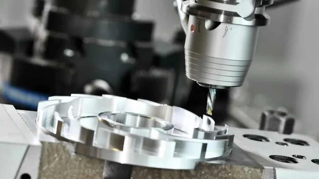
CNC Machining and Allowance
In CNC machining, allowance is the difference between the maximum shaft size and minimum hole size. For systematic design:
- Clearance allowance > 0 (e.g., hole 10.05 mm, shaft 10.00 mm, allowance = 0.05 mm).
- Interference allowance < 0 (e.g., hole 9.95 mm, shaft 10.00 mm, allowance = –0.05 mm).
Allowance guides whether a part slips, fits tightly, or requires force, essential in mechanical design.
Try Prolean Now!
Allowance and Engineering Fits
Understanding how parts fit together is necessary for performance. The concept of allowance intentionally defines the difference of size between intercourse parts, while engineering fits describe the relationship between those parts once assembled.
The correct fit choice depends on the function – whether parts must move freely, fit tightly, or require controlled pressure during the assembly.
There are three main types of engineering fit used in mechanical designs and CNC machining. Each has a different purpose and is chosen based on the role of components.
1. Clearance Fit
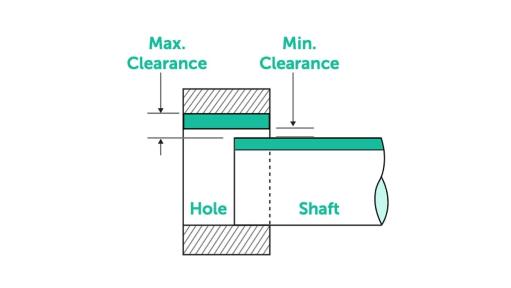
Shaft and Hole Clearance Fit
A clearance fit ensures that there is always place between the shaft and holes. The shaft is deliberately made smaller than the hole, allowing for smooth, easy assembly without any force.
It is fit ideal when parts should be moved independently, such as shafts, slides, or guiding components. Common examples include fan blades, axles or pulleys.
Clearance fits reduces and wears friction, but must be controlled to avoid excessive looseness that could impact accuracy or create vibration.
2. Transition Fit
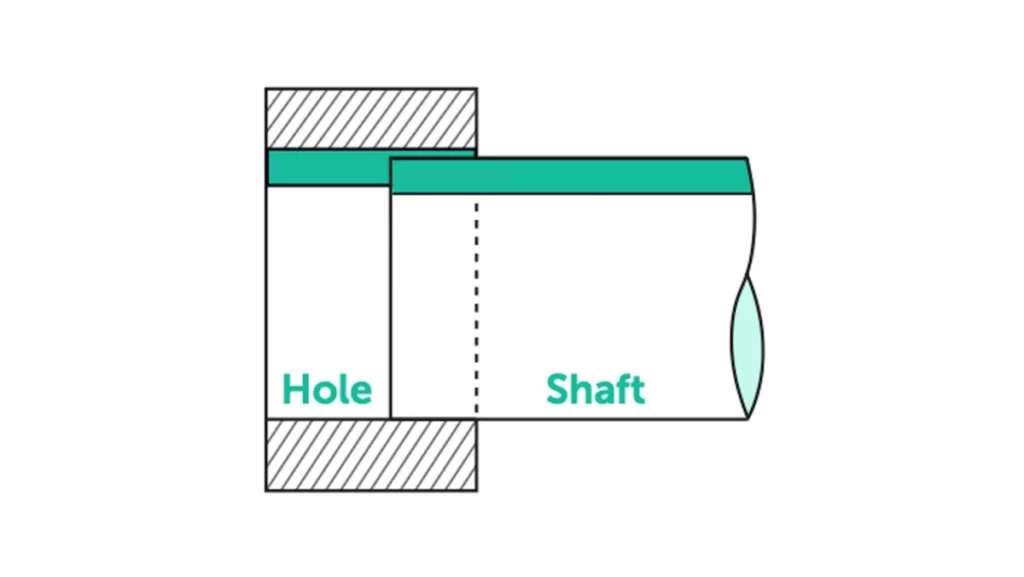
Transition Fit: Hole and Shaft
A transition fit is a compromise between clearance and interference. Depending on the exact dimensions and tolerance applied, it may fit a snug but a movable assembly or a minor press fit.
It may require light pressure or equipment to assemble the parts. This type of fit is used, where accurate alignment is required without permanent locking – such as in gear mounted in shafts, coupling, or mechanical sleeves.
It balances ease of assembly with tight control over movement or play between parts.
3. Interference Fit
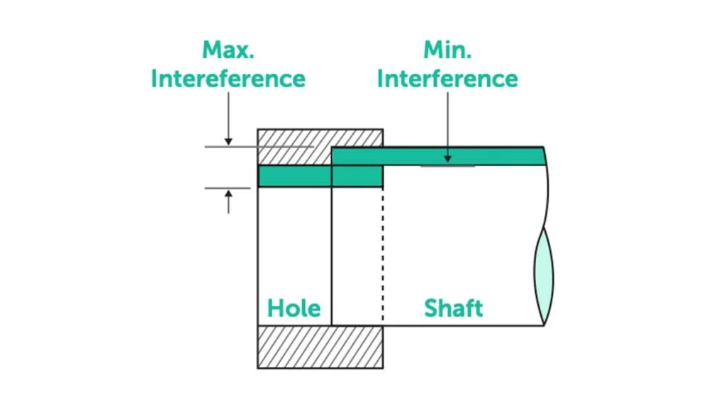
Interference Fit: Hole and Shaft
An interference fit (also known as press fit) occurs when the shaft is intentionally larger than the hole. This requires the force, heat shrinking or suppressing equipment for assembly. Once included, the part will not move relative to each other.
This fit is used when a firm, permanent connection is required – such as in wheels, bearing, race, or structural pin.
The interference is important for fit strength and reliability, but requires accurate machining and accurate allowance control to avoid damage during assembly.
Why Engineering Fits Matter?
The selection of the right fit type is not just a design option – it affects the function, performance and durability of your product. The rotation or sliding components demand clearance for smooth movement.
Load-bearing joints or permanently joined parts require interference fits to handle stress and prevent slippage. The transition fit provides flexibility in the middle.
At ProleanTech, we help customers select ideal tolerance and allowance settings to ensure the right fit every time.
Learn more about how different materials affect design and precision in our guide to Common Materials for CNC Machining.
Why Allowance Matters in Production?
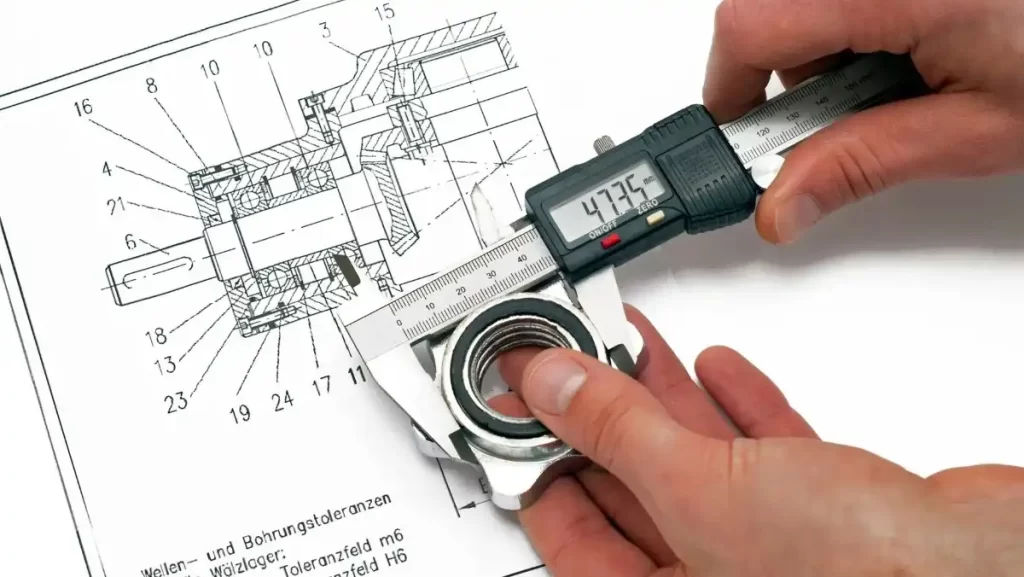
Precision Measurement for Production Allowance
Allowance plays a critical role in how well parts assemble and perform in real-world applications. This is not just about the design – it’s about how strong your parts fit during production and how efficiently your assembly lines operate.
The correct allowance ensures smooth operation, reduces errors, and supports the quality of the product constantly in the batches.
- Assembly Reliability: Prevents the cart or looseness.
- Manufacturing Feasibility: account for machineing variation.
- Product Performance: Ensures the right speed or hardness.
Benefits of Including Tolerance and Allowance in Parts’ Design
Precision Measurement of Part Design
It is not optional to integrate proper tolerance and allowance in your design-it is necessary for efficient, high quality production. These design factor affect everything from costs and speeds to the performance and long -term durability of the part.
When planned correctly, they reduce the risk, increase repetition, and support scalable manufacturing processes. Here are some benefits:
- Low failure rate – good tolerance means less rejection.
- Cost efficiency – A comfort tolerance machine saves time.
- High recurrence – batch parts match firmly.
- Clear specification – helps machineists and engineers to avoid errors.
By combining tolerance and allowances, you design parts that complete the performance goals cost-effectively.
Summary Table: Tolerance vs. Allowance
Allowance = designed fit difference, Tolerance = allowed variation.
Here are the key differences between tolerance and allowance:
| Attribute | Tolerance | Allowance |
| Definition | Permissible variation from a nominal dimension | Intentional difference between mating parts |
| Purpose | Limits variation around nominal | Creates fit difference between parts |
| Variation | ± range (e.g., ±0.04 mm) | Fixed gap or interference (e.g., –0.02 mm) |
| Function | Quality and consistency | Functionality and assembly of mating parts |
| Control | Inspector key | Design engineer key |
| Example | 20 ±0.05 mm | Hole 20.10, shaft 20.00 → +0.10 mm allowance |
Check this guide to understand where tolerance and allowance factor into the machining cycle.: https://proleantech.com/production-cycle-time-in-cnc-machining/
Your Machining and Manufacturing Expert: ProleanTech
ProleanTech: Machining and Manufacturing Expert
Need help with tolerance and allowance, precision parts or engineering guidance? ProleanTech is your go to expert. Our engineers:
- Advise on fits and tolerances based on ISO standards and GD&T.
- Optimize CNC processes to reduce cost and increase yield.
- Offer equipped services—consulting, prototyping and production.
At ProleanTech we know your pain: tight schedules, part failures, assembly delays. We solve it with engineering know how and great service.
Check out: Top 9 CNC Machining Manufacturers in The World
In a Nutshell
Tolerance and allowance are the foundation of precision engineering. Tolerance controls size variation; allowance controls fit. Together they determine how well parts perform and assemble. Use dimension, general and GD&T tolerances wisely.
Choose the right fit type—clearance, transition or interference—based on your product needs. This will give you reliable and cost effective parts.
If your business relies on precision manufacturing, we can help with expert consulting, efficient CNC production and unmatched quality. Contact us now for our China CNC Machining Services and get your quote now!
FAQs
Q1. What is the difference between tolerance and allowance?
Tolerance is an acceptable variation (+/- range), while the allowance is a deliberate size difference (gap or overlap) between intercourse parts.
Q2. What is meant by tolerance in machining?
In machining, tolerance is how much a manufactured part can be distracted by its nominal dimension and is still acceptable.
Q3. How to calculate tolerances?
Subtract minimum from maximum limit. For example, if 10±0.05 mm, tolerance = 0.10 mm.
Q4. What is an example of tolerance?
A hole specified as 15+0.02/–0.00 mm means that it can vary between 15.00 and 15.02 mm.

0 Comments