Slip Fit Tolerance and Geometry Significance
Have you ever tried to fit two metal parts simultaneously, but they didn’t quite align? This is the place where slip fit tolerance helps. This ensures that one part can still slide into another smoothly, while aligning things properly.
Slip fit is a smart way to connect parts to industries such as automotive, aerospace, robotics and tooling. They help machining parts slide together easily without being too loose or too tight.
If your business needs an accurate fitting, ProleanTech is here to help. We provide specialist advice and custom manufacturing services for slip fit tolerances.
In this blog, we will explain what slip fit is, why tolerance matters, and how geometry affects fit and performance.
What Is a Slip Fit?
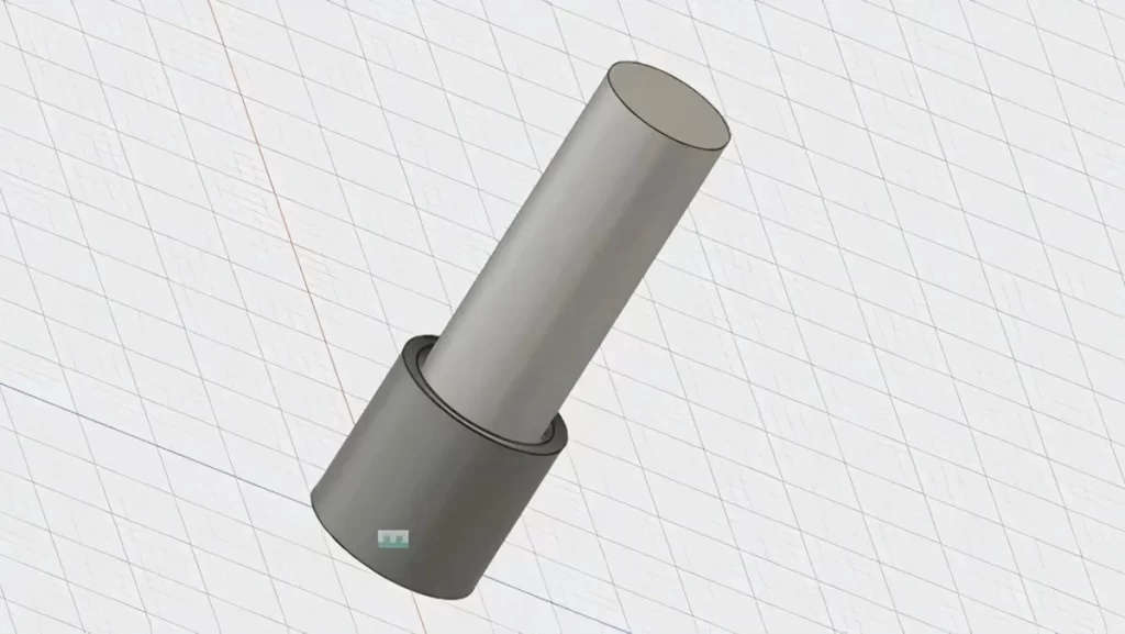
A slip fit is a type of clearance fit that allows a part (such as a pin or shaft) to easily slide into the other (such as a hole) with minimal play. Unlike the press fit, which requires force, slip fit depends on controlled tolerance intervals.
The objective is clear: smooth assembly and decissam, enabling repeatable alignment, and reducing assembly effort without renouncing accuracy.
What is Slip Fit Tolerance?
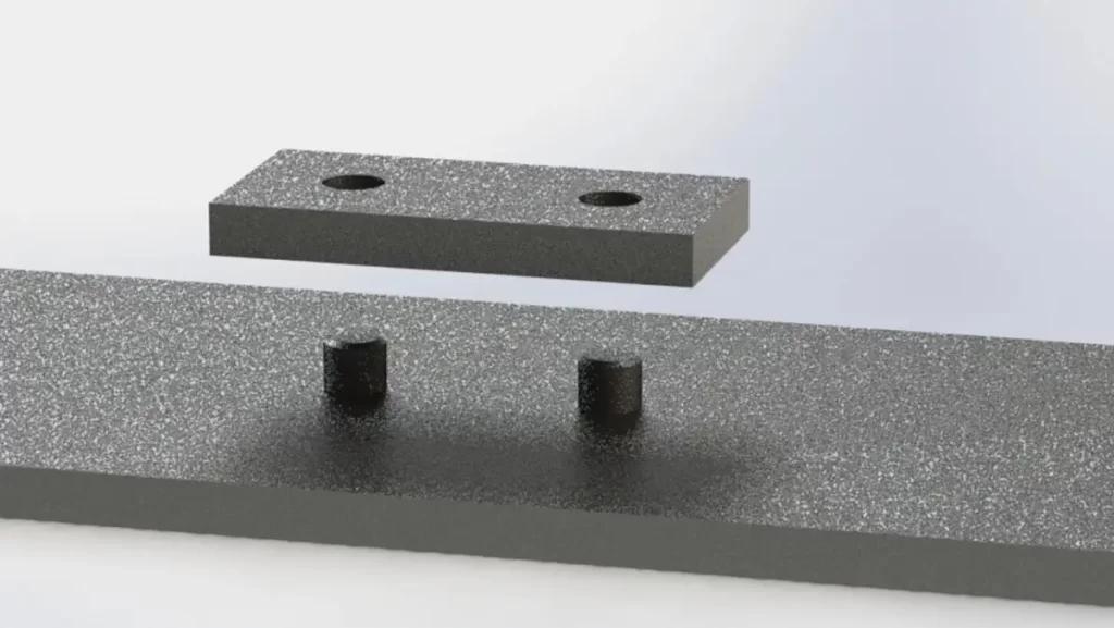
Understanding Slip Fit Tolerance Visually
The slip fit tolerance refers to the allowable difference in size between the shaft and the hole. The shaft is slightly smaller than the hole to allow a smooth slide fit.
This tolerance range is carefully selected on the basis of border function, material type, machining method and application using CNC precision machining techniques.
Slip fit tolerance is designed for:
- Stop binding during assembly
- Allow to move parts without excessive play
- Ensure repeatability in production
- Adjust slight machining or thermal variations
Why Is Tolerance Important?
No two machine parts are exactly the same. The variations in cutting tools, temperatures, and machines may slightly change the size of a part. Tolerances account for these small changes and ensure parts still fit and function.
If you need a better understanding of these concepts, check our related post on: CNC Machining Tolerance.
Slip Fit Tolerance Table
Let’s look at some common slip-fit tolerance ranges. These values vary depending on the fit class (loose, medium, or tight), the part’s size, and application. The ISO system and ANSI standards are commonly used worldwide.
Here is a basic slip fit tolerance table for various shaft sizes:
| Nominal Shaft Diameter (mm) | Hole Tolerance (H7) | Shaft Tolerance (g6) | Clearance (µm) |
| 6 to 10 | +0 / +15 µm | -7 / -20 µm | 7 to 35 µm |
| 10 to 18 | +0 / +18 µm | -8 / -22 µm | 8 to 40 µm |
| 18 to 30 | +0 / +21 µm | -9 / -25 µm | 9 to 46 µm |
| 30 to 50 | +0 / +25 µm | -11 / -30 µm | 11 to 55 µm |
| 50 to 80 | +0 / +30 µm | -13 / -36 µm | 13 to 66 µm |
Note: These values are only examples. See the official ISO 286 or ANSI B4.1 chart for exact slip fit tolerance data.
Fit examples under ISO 286:
- H7/g6 – Loose Slip Fit
- H7/h6 – Close Slip Fit (minimal clearance)
Read More: CNC Machining Explained
Standard H7/g6 or H7/h6 fits provide a baseline, but actual clearance can shift due to machining variation and assembly forces. Collaborate with our precision tolerance experts to confirm real fit performance before production begins.
What are the Types of Tolerances?
To define the accurate fits and to ensure optimal functionality, it is important to understand a variety of tolerances:
1. Dimensional Tolerances
Technical Drawing: Dimensional Tolerances Defined
These tolerances control physical dimensions (length, width, diameter).
- Unilateral Tolerance: Allows variation in only one direction from the nominal size. Example: 10.00 mm +0.05/-0.00 mm.
- Bilateral Tolerance: Allows variation in both directions. Example: 10.00 mm ± 0.05 mm.
- Limit Tolerance: Specifies the upper and lower dimensional limits, such as, 9.95 mm to 10.05 mm.
2. Geometric Tolerances
Technical Drawing with Geometric Tolerances
These govern the shape and positioning of part features..
- Form Tolerances: Straight, flatness, roundness, cylindricity
- Orientation Tolerances: Vertebrality, equality, angularity
- Location Tolerances: Position, concentricity, symmetry
- Runout Tolerances: Control speed stability in rotating parts
Use these tolerance types to control manufacturing quality, especially for parts requiring frequent alignment.
Try Prolean Now!
What Is the Maximum Clearance of a Fit?
The maximum clearance of a slip fit depends on the tolerance range of the hole and shaft.
Formula: Max Clearance = Largest Hole Size – Smallest Shaft Size
Typical values range from:
- 0.0015” to 0.0040” for standard slip fits
- ≤0.0020” for high-precision fits
Exceeding these clearances can lead to poor alignment and potential vibration.
What Are Typical Standard Tolerances?
In manufacturing and engineering, it is practically impossible to obtain the right dimensions. This is where the concept of “tolerance” becomes important, defining permissible variations in the shape or form of a part.
It is necessary to understand specific standard tolerance, contradiction in an assembly, proper fit and overall functionality of components.
Standard machining tolerances vary depending on the process used:
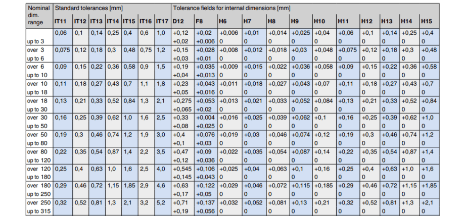
Standard Tolerance Table for Internal Dimensions
You can explore full-scale engineering and manufacturing workflows to see how tolerances are maintained across processes.
Interesting Read: Multi-Axis CNC Machining
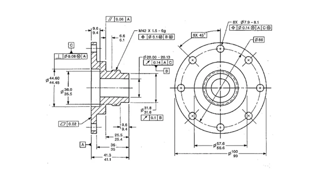
Slip Fit Tolerances and Geometry
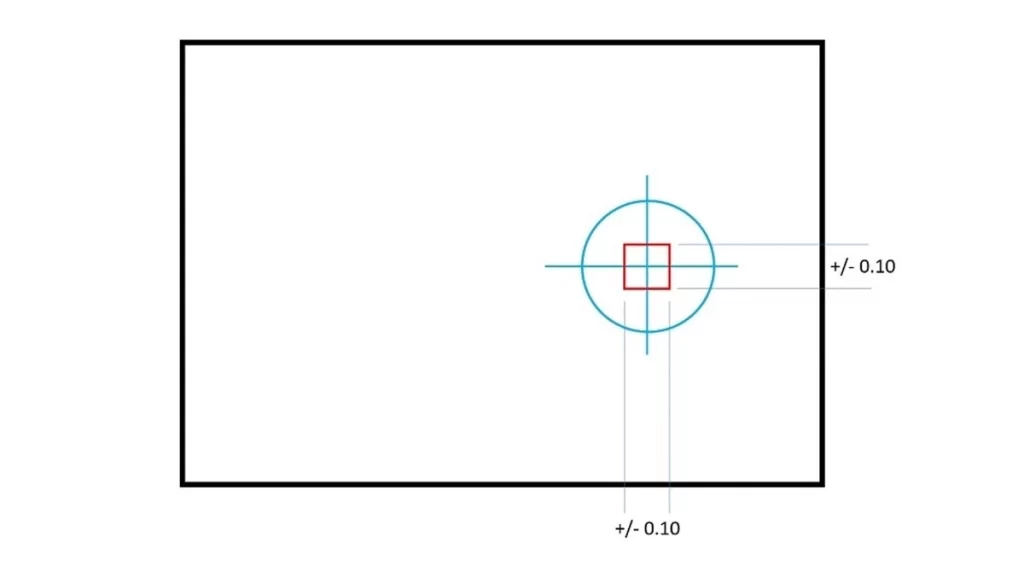
Slip Fit Positional Tolerance Diagram
Slip fit tolerance defines the accepted difference in size between mating parts. These tolerances are important when using dowel pins, shafts, and guides in fixtures and assemblies.
Typical slip fits need to be slightly larger than the hole or shaft. This difference is usually between 0.0005 “to 0.003”, which depends on the size and use of the part.
Designers must also consider:
- Surface finish
- Material behavior under temperature
- Manufacturing precision
These elements at once affect how smoothly components will suit together. ProleanTech offers tight-tolerance machining with expert finish control to make certain best fits every time.
Try Prolean Now!
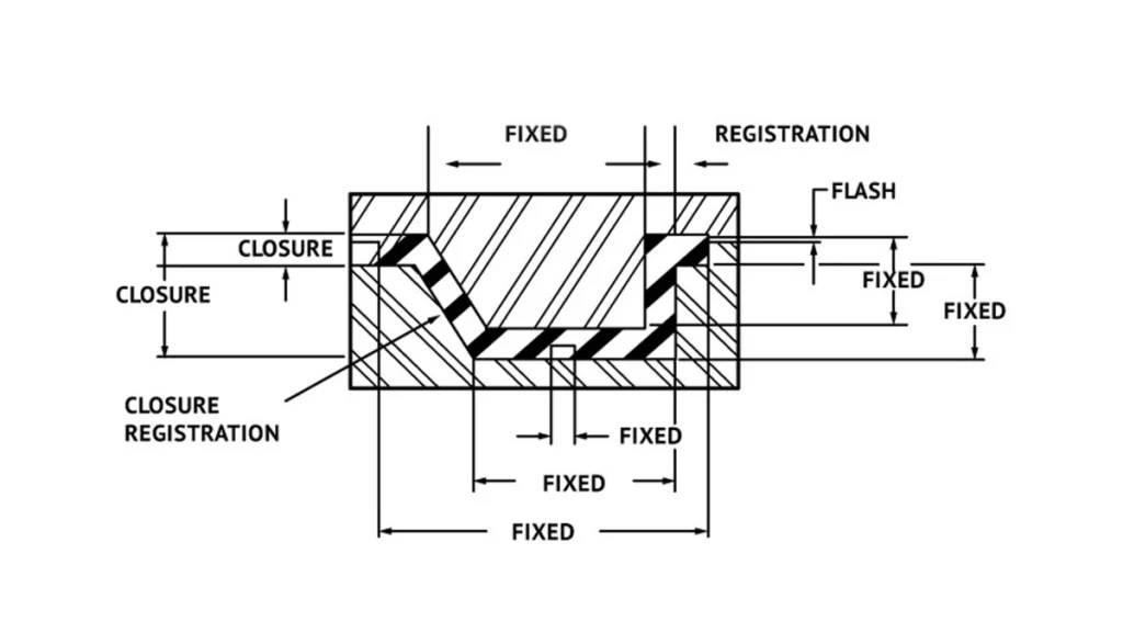
Slip Fit in GD&T Practices
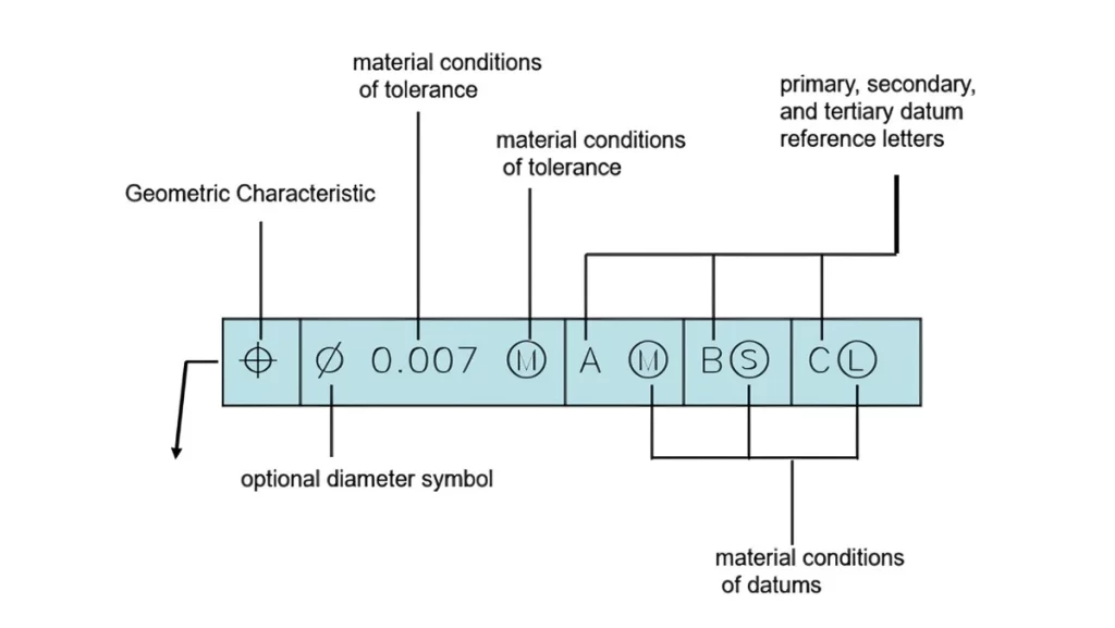
GD&T Feature Control Frame Explained
The use of GD&T with sliding adjustments allows for better control over how parts align and operate. See how this improves the performance of sliding adjustment:
- Datums define reference surfaces
- True position guarantees the alignment between the mating holes
- Cylindricity keeps roundness for soft fitting
Example: Two dowel pins that align a CNC plate must have hole positions defined with tolerance and perpendicularity of the true position to a datum surface.
Why Modern Tolerancing Is Better?
Legacy tolerancing using +/- values creates a square zone of variability, which can misalign parts despite being “in tolerance.”
Instead, modern design uses Geometric Dimensioning and Tolerancing (GD&T) to:
- Control true position of holes
- Maintain perpendicularity and orientation
- Specify form (like cylindricity) for perfect sliding
Use GD&T when you need precision without overengineering.
How Is Slip Fit Achieved in Manufacturing?
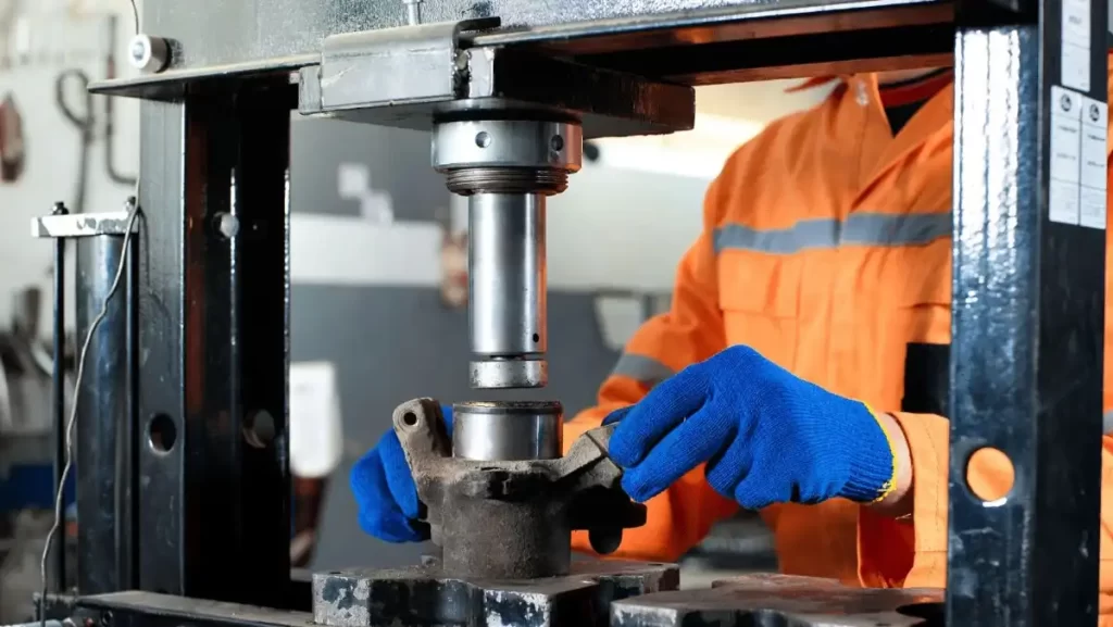
Manufacturing Slip Fit Using Press
To get a proper slip fit, engineers must ensure that the hole is slightly larger than the mating part – just enough to allow smooth insertion without enough game.
For example, a 0.250″dowel pin usually requires a hole diameter between 0.2515″ and 0.253″. This gap makes the required clearance fit while maintaining alignment accuracy.
Manufacturing should maintain strict process control to consistently complete these tolerances. Even slight changes in tooling or material expansion can affect fit quality.
For blind holes, the design should be responsible for air displacement. If there is no way to escape, the stuck air can resist the insertion. To ensure functional slip fits:
- Over-size the hole with accuracy depending on the component dimensions.
- Maintain tight machining tolerances to prevent misalignment.
- Include venting relief or side flats for blind holes.
These steps guarantee smoother assemblies and longer-lasting performance. At ProleanTech, we handle all these factors to deliver perfect slip fits in every batch.
Slip Fit Fundamentals and Use Cases
For a slip fit to function effectively, it must meet three essential conditions.
First, the shaft should always be slightly smaller than the corresponding hole, ensuring smooth insertion without applying force.
Second, the fit should be responsible for natural variations due to machining processes and material properties, which can affect the final dimensions.
Finally, the clearance between the parts should be sufficient to prevent binding, but not so much that it compromises the alignment. This balance continuously ensures assembly and disassembly, especially in components requiring high repeatability.
Here are the common applications:
- CNC fixtures and modular tools
- Mold inserts
- Machine alignment pins
- Bearing housings (non-rotating components)
For design professionals, slip fits mean faster part interchangeability and lower tooling costs.
Tips for Designing with Slip Fit Tolerances
Slip Fit Design CAD Model
An effective slip fit design requires only selecting the shape of a shaft and hole—it demands careful attention to real-world variables like materials, machining limits, and assembly needs.
By following some major design tips, you can ensure smooth assembly, reliable performance, and cost-effective manufacturing.
Let’s find out the most important practices to achieve slip fit tolerance.
- Use Standard Tolerances: Stick with ISO or ANSI standard fits like H7/g6 for predictability and ease of sourcing.
- Consider Material Expansion: Materials like aluminum expand more than steel. Adjust tolerances for thermal variations.
- Include Chamfers or Lead-ins: Eases assembly and prevents jamming of the shaft during insertion.
- Check Machining Capability: Tighter tolerances need precision tools and quality control. Balance function with cost.
- Use Gauge Tools: For consistent quality in production, use Go/No-Go gauges to verify slip fit limits.
ProleanTech uses all these best practices to give you quality parts with fewer errors.
Conclusion
When it comes to mechanical reliability, slip fit tolerance is your secret weapon for precise, cost-effective, and repetitive assembly.
Whether you are an OEM manufacturer or a prototype startup, applying appropriate fit principles can prevent expensive alignment errors and improve productivity.
Our experts at ProleanTech offer world-class CNC Machining Services tailored to your exact tolerancing requirements. We deliver solutions for sectors like aerospace, automotive, industrial tooling, and more.
We specialize in close-tolerance components for aerospace, automotive, medical, and industrial automation sectors. Contact with our experts team today to design better with slip fit.

0 Comments