Sheet metal bend radius
Sheet metal bend radius is a critical design element in sheet metal fabrication. It is the inside radius of a bent sheet, and it determines whether the sheet deforms as designed, provides the expected dimensional accuracy, and doesn’t crack under force.
Notable factors to consider when choosing the bend radius are the workpiece material, bend angle, and springback effect. With the correct accommodation of different bending dynamics, such as the bend diameter and bending allowance in sheet metal, manufacturers can always deliver quality sheet metal parts.
This article shares useful sheet metal bend radius guidelines so that your upcoming projects can always conform to standards and your requirements.
What is Sheet Metal Bend Radius?
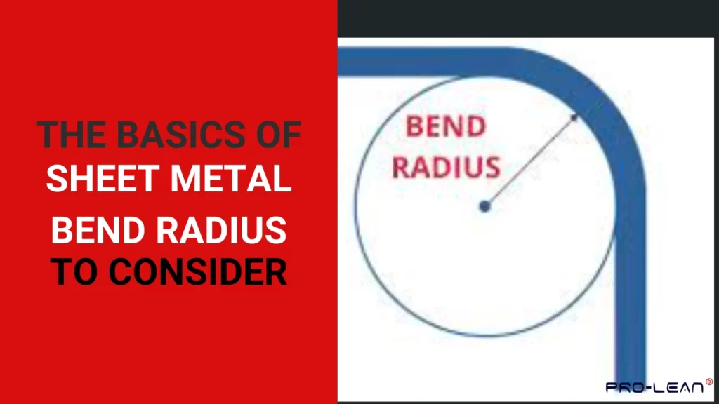
Sheet metal bend radius is the distance between the inner surface of a bent metal sheet to the imaginary center point of the bend.
Bend radius
This measurement is critical because it determines the stress a metal experiences during the bending process. If the bend radius is too small, there is a risk of cracking or even failure at the bend line. This can compromise part integrity and manufacturing efficiency.
Bending design best practices recommend a minimum bend radius for sheet metal, usually as a multiple of the sheet thickness. Different materials have their minimum bend radii.
Why is the (Minimum) Bend Radius Important?
The minimum bend radius matters because getting it wrong gives room for poor part fit, metal cracks, and potential for unnecessary job reworks. Industry best practice has come up with minimum bend radii that save fabricators these issues, and ensure project success all the time.
Other Common Bending Terms and Their Relevance
Apart from the sheet metal bend radius, there are important related terms such as bending direction, bending height, bending tool interference, and bent flange interference.
These terms are defined below:
Bending Direction
Due to the anisotropic behavior of metals, the direction of the bend in relation to the grains matters. If sheet metal bending methods are done along the grains, cracks, tears, and other defects can occur.
Sheet metal fabrication experts bend sheet metal perpendicular to the grain direction to not only prevent these defects but also ensure optimal bend strength.
Bending Height (H)
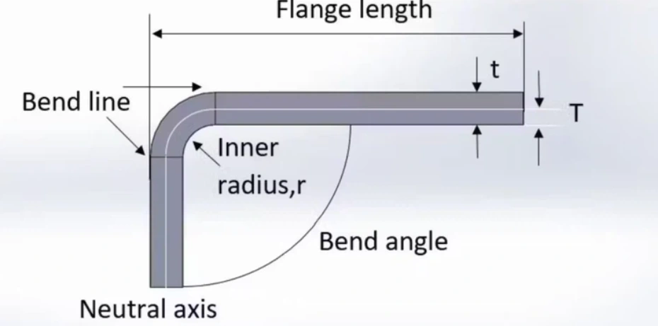
Bending height is the length of the resulting flange after a sheet of metal has been bent. While this length can be as large as necessary, there is a minimum for it. As a rule of thumb, the bending height should be greater than or equal to the sum of the bending radius and 2 times the thickness.
H ≥ 2t + R
Bending Tool Interference
The bending tool requires space to operate, hence the need for bending tool interference consideration. If the features extend to the bending area, the resulting bend radius and other components may not be as designed because the tool’s performance is interfered with.
Features should be at a distance to ensure proper application of custom radius tooling for metal bending. The rule of thumb is similar to that of the bending height – a feature above the bend area should be at least a distance of the bending radius added to 2 times the thickness.
H ≥ 2t + R
Bent Flange Interference
When designing a box or component involving multiple walls, the shared corners should be considered. Since the flanges can easily interfere and affect the design, an allowance (offset) is typically provided.
It might be tempting to provide a large offset to make the bending process simpler. However, welding may be problematic where the gap is too big. A 0.2mm offset is normally enough.

Bending flange interference
What is Sheet Metal Hemming?
Sheet metal hemming is considered a type of sheet metal bending where the sheet is folded back on itself. The bending is usually done to 180 degrees, resulting in a finished edge. Hemming is a common process in the automotive industry, where it helps achieve enhanced aesthetics, strength, and safety for sheet metal parts.
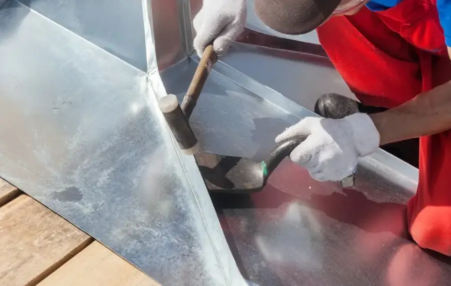
Sheet metal hemming
Factors to Consider in Determining Bend Radius
Determining the correct bend radius is a matter of balancing several variables, including the workpiece material type and thickness, the required bend angle, the sheet metal bending techniques used, and the material’s behavior during bending.
Each of these factors affects the rest. ProleanTech uses effective strategies based on these factors to prevent defects while optimizing tooling setup and minimizing material costs.
Workpiece Material Type and Thickness
This is one of the most critical factors in determining sheet metal bend radius. Since materials have different properties, the capability to bend differs. Ductility is a major property – the level of ductility determines how much a material can bend without cracking.
Consider a comparison between high-strength steel and aluminum. High-strength steel cannot accommodate small bend radii without cracking, but aluminum can.
Bending a thick HSS sheet
According to industry best practices based on material type and thickness, here are some recommendations for minimum bend radius;
- Aluminum: K = 2.0 – bend radius is 2 times the thickness
- Mild Steel: K = 1.5 – bend radius is 1.5 times the thickness
- Stainless Steel: K = 2.0 – bend radius is 2 times the thickness
Where K is a special multiplier also called the bend radius factor.
Bend Angle
The bend angle also influences the ideal bend radius. A larger bend angle means more stress on the material and a subsequent requirement for a larger radius.
Acute bend angles introduce localized stress that can cause cracking in the material unless a large enough bend radius is used.
From best practice, bends more acute than 90° require larger radii. If the bend angle is smaller than 30°, it is advisable to use softer materials, resort to advanced forming techniques, or avoid such an angle altogether.
Acute bend angle
Bend Allowance
This is the measurement or distance on the flat sheet that will account for the bend radius.
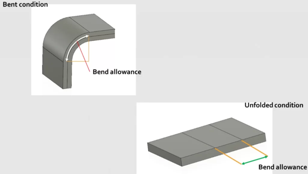
Bend allowance
Understanding the K Factor in Sheet Metal Bending
The K factor in sheet metal fabrication is the ratio of the neutral axis distance to the material thickness. It is a key determinant of a material’s capability to bend and stretch during bending.
Usually between 0.3 and 0.5, this factor is useful during bend deduction and bend allowance calculations, with softer materials having a higher rating.
Springback Effect
Springback is a phenomenon whereby a bent material tends to return to its original shape when the bending force is removed. The extent of this effect depends on the elastic properties of the material.
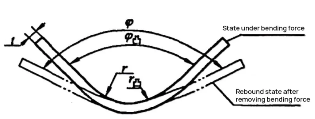
Springback
This effect is equally critical for sheet metal fabrication designs when determining the bend radius. Factors of this effect include the bend angle and material hardness.
Try Prolean Now!
Industry Standard Sheet Metal Bend Radius
The best approach when designing for the minimum bend radius sheet metal is to use the industry standard of 0.030”. This measurement guarantees consistent and high-quality parts.
When to Deviate from the Industry Standard Bend Radius of 0.030
The 0.030” bend radius is recommended for part thicknesses of 0.125″ (⅛”) and below. Designers should deviate from this standard for any part thicker than 0.125″ (⅛”), increasing the radius as it might be necessary (proportionately).
Using larger radii for bigger materials is necessary to prevent cracking or failure.
Deviating from this standard may also be necessary in these other scenarios:
- Bending limitations of specific materials
- Specific functional or aesthetic requirements
- Part assembly constraints
What Is The Rule of Thumb For Bending Sheet Metal
A good rule of thumb in bending sheet metal is to maintain an inside bend radius at least equal to your sheet’s thickness to prevent distortion or cracking.
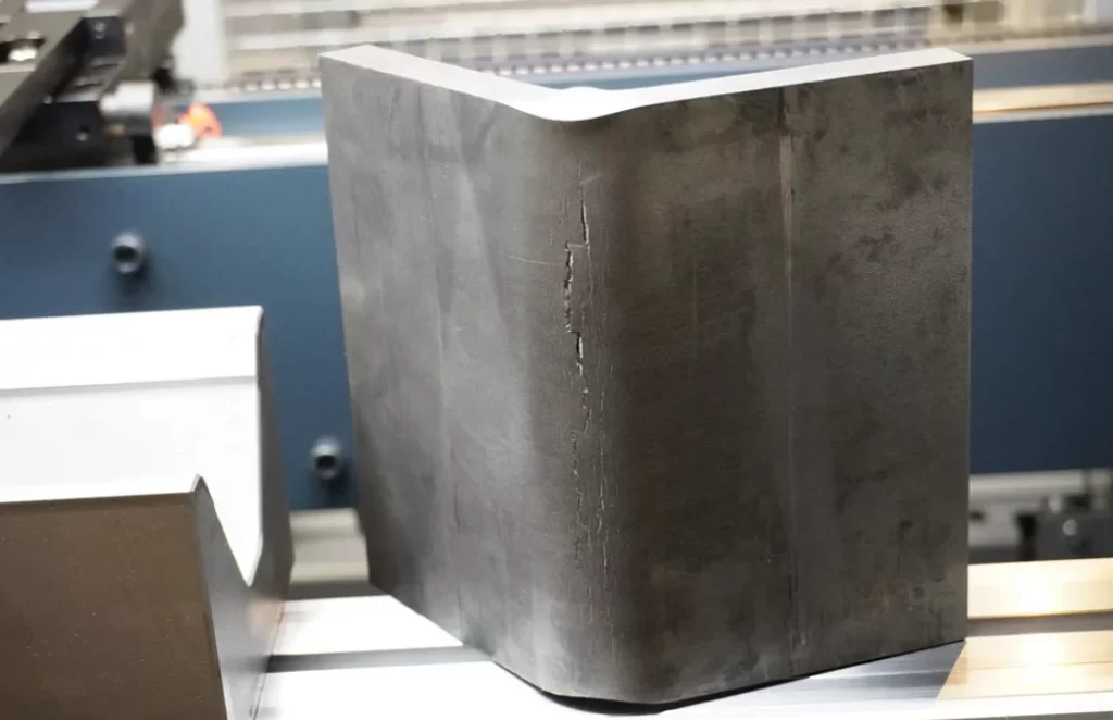
Cracks in bent sheet metal
This baseline provides a reliable starting point for the most common sheet metal materials and applications. However, note that the factors discussed above may determine the bending requirements for specific alloys and tighter tolerances.
Other rules of thumb, as mentioned in other sections of the article, are;
- Bending Height Rule: H ≥ 2t + R
- Bending Tool Interference Rule: H ≥ 2t + R
- Bent Flange Interference Rule: 0.2mm offset for shared corners in box designs
How to Find Bend Radius
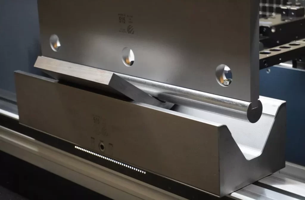
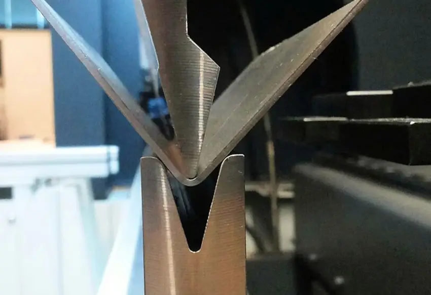
There are three steps to finding the bend radius: Determine the sheet thickness, choose the V-shaped die opening, and calculate the bend radius. So, determining the bend radius for any particular material is a systematic process that takes into account material specifications and tooling setup. Manufacturers usually rely on air bending and V-bending techniques.
There is no big difference between air bending and V-bending. While V-bending forces the sheet material to attain the exact shape of the die, air bending allows for some flexibility.
Manufacturer charts provide reliable guiding ratios for material thickness against V-die opening width. These ratios determine the radii that can be achieved by a material and the bending machine.
Get a quote and learn how experts use charts and best practices to arrive at the optimal bend radius.
Use of Sheet Metal Bend Radius Charts
Since manual calculations can be time-consuming, press brake operators and engineers use sheet metal bend radius charts. One only needs to know the type of material and its thickness. The reference to the table gives the minimum bend radius.
Here is a shortened form of the minimum bend radius reference table.
| Material | 1–6 mm | 6–12 mm | 12–25 mm |
| Aluminum | 1T | 1.5T | 2-3T |
| Steel | 0.8T | 1.2T | 1.5-2.5T |
| Stainless steel | 2T | 2.5T | 3-4T |
Try Prolean Now!
Sheet Metal Bend Radius Calculation Example
Consider a scenario where an 8 mm-thick stainless steel sheet is being bent. Sheet metal bending calculation for the bend radius is required. According to the bending radius reference table shared above, the minimum bending radius would be;
R = 2.5T
= 2.5*8mm
= 20mm
Common Bend Radius Design Mistakes
The most common bend radius design mistakes entail taking the inside bend radius as equal to the material thickness and specifying 0.100″ as the default bend radius without considering the part’s requirements.
These mistakes can easily drive up manufacturing costs and increase lead times.
- Bend Radius Equal to the Thickness: This can cause problems, especially with common materials, because it can trigger the need for custom radius tooling for metal bending.
- 0.100″ as the Default Bend Radius: Standard tooling cannot produce a 0.100″ bend radius. Custom radius tooling for metal bending is expensive.
Conclusion
Careful consideration of the bend radius is the secret to producing quality sheet metal bent parts. By ensuring adherence to the best practices of sheet metal bending, you can always have products that match design requirements.
If you need help in sheet metal design and manufacturing, ProleanTech is the answer. Contact us today for expertly designed and executed sheet metal bending services.

0 Comments