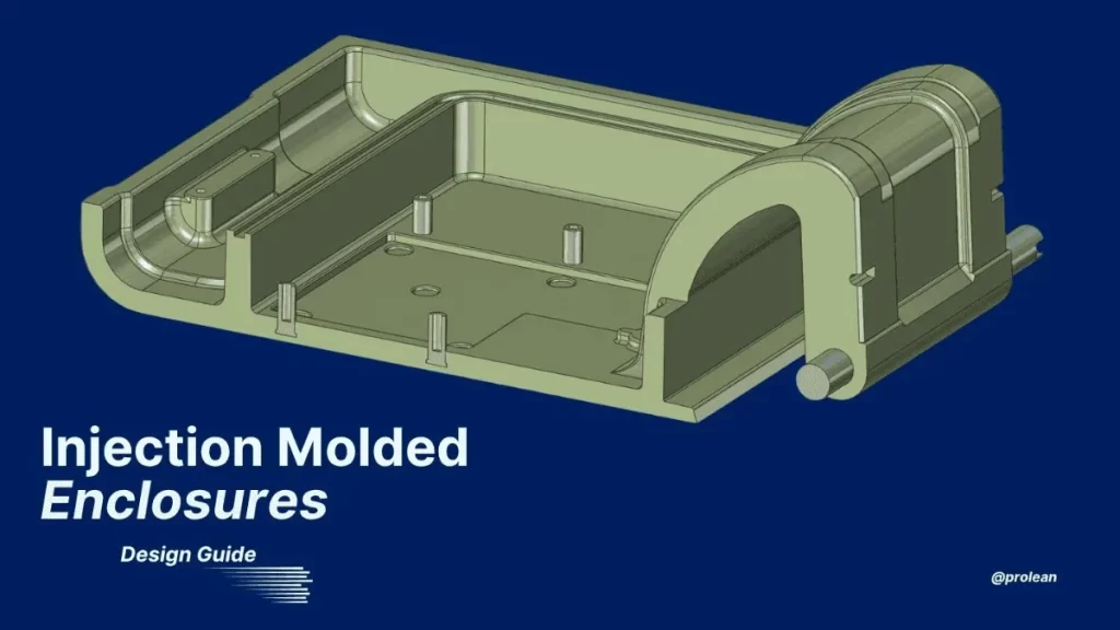
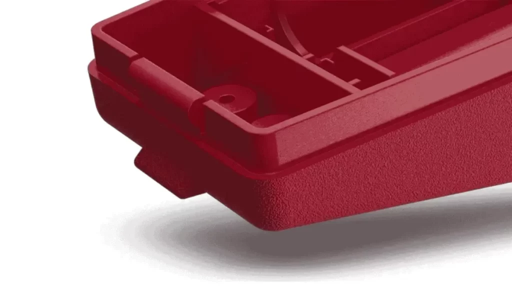
Injection Molded Enclosure
The manufacturing process plays a key role in the final result when creating custom plastic enclosures, whether for electronic enclosure design, industrial tools, or consumer products. Custom Injection molding is one of the most reliable methods for producing durable and accurate enclosures, but it comes with design considerations.
At Prolean Tech, we understand that every product has unique requirements. Whether you’re developing housing for a smart device, an EV charging panel, or a medical unit, your design must balance strength, appearance, and function. That’s why choosing the right material and mold design is essential.
With years of hands-on experience in custom injection molding, our team helps you shape your enclosure designs to meet real-world demands. We aim to support product developers with practical advice and solutions that streamline the path from idea to finished product.
Design Guide for Custom Plastic Enclosures Using Injection Molding
Here’s our practical approach to establishing a product-ready custom injection molded enclosure design.
User Experience and Assembly Fit
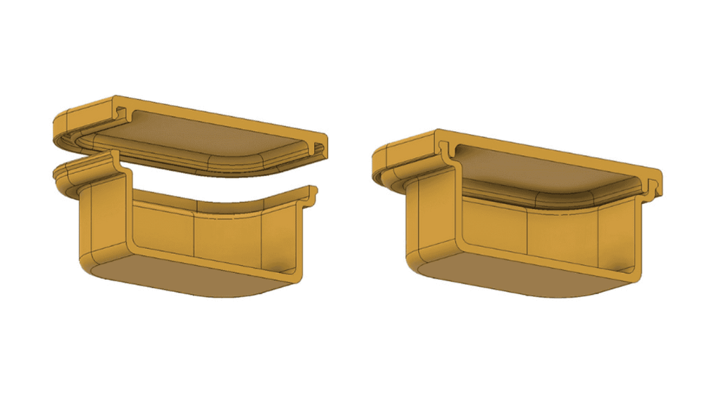
Fitment Test for Enclosure
Understanding the interactions of users is how one begins designing injection molded enclosures. Consider how your customers will open, handle, and get to the product. Will it be wall-mounted? Does it need frequent servicing? These are very essential points to consider before you model a feature.
The primary aim is to design with your end-users’ experience kept in mind – not only for internal parts, but also for how your enclosure integrates with actual applications.
As you make this early consideration, you also need to consider the way internal parts are assembled. Make sure that each feature fits well and is neither loose nor rough.
Determine any zones that may influence usability and product lifespan where alignment, clearance, or interference have an impact. When something appears ambiguous, it’s time to think about prototyping.
Prototype construction allows testing critical areas, particularly where snap fits, mating parts, and hinges are concerned. It will enable your team to measure tolerances and ensure that parts fit and function properly together. This eliminates expensive surprises down the production line, particularly once tooling is underway.
In-Mind Designing with Injection Molding
3D Enclosure Design for Injection Molding
Injection molding is quick, scalable, and precise, provided that the design aligns with manufacturing principles. Every curve, wall, and feature must be mold-ready. It means simplifying things, predicting tool movements, and avoiding problems that may compromise quality or lead to defects. At Prolean Tech, we consider such details early in your design so that your product is not only manufacturable but also efficient in function.
Gate Placement
Solving Gate Problem In Injection Molding
The gate is where molten plastic is introduced into the mould cavity. Although it is a minor feature, the gate position impacts resin flow, appearance, and strength.
Suboptimal gate placement can lead to air traps, weld lines, and sink marks. You should place the gate close to the thicker parts of your part and outside cosmetic areas. Best results can only occur when the gate location is always part of the early mold design process, not an afterthought.
Try Prolean Now!
Wall Thickness and Structural Balance
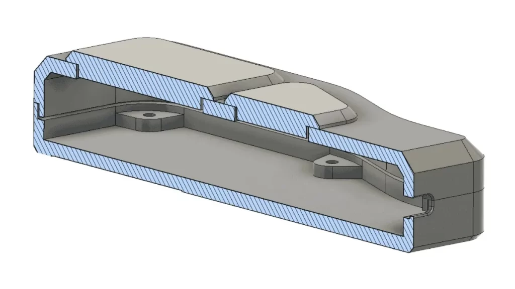
Wall Thickness Arrangement In Injection Molding
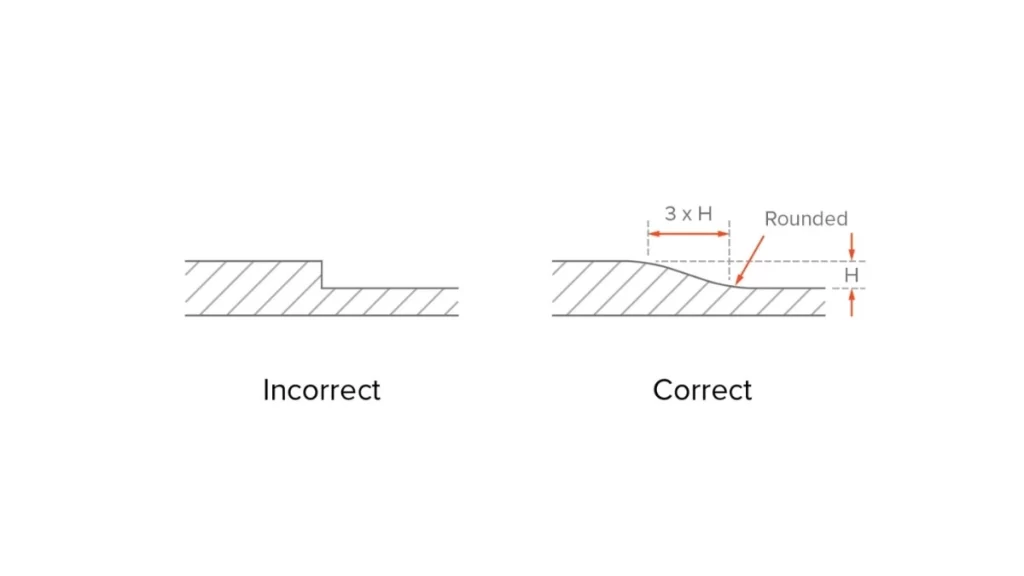
The most critical design element of your enclosure is wall thickness. Consistency of wall thickness promotes equal cooling. Thus, it eliminates injection molding defects like internal stresses and warping, or sink marks. Ideally, you can maintain the walls between 1.5 mm and 3 mm. This gives adequate material for structural integrity with low cycle times.
If your designs require some thick regions, then make the transition smoothly. Steep thickness variations lead to flow issues and nonuniform shrinkage. Additionally, plastics are inefficient when transferring heat; differently warmed walls will give off different cooling rates, causing twisting and cosmetic problems.
Ribs and Bosses for Reinforcement
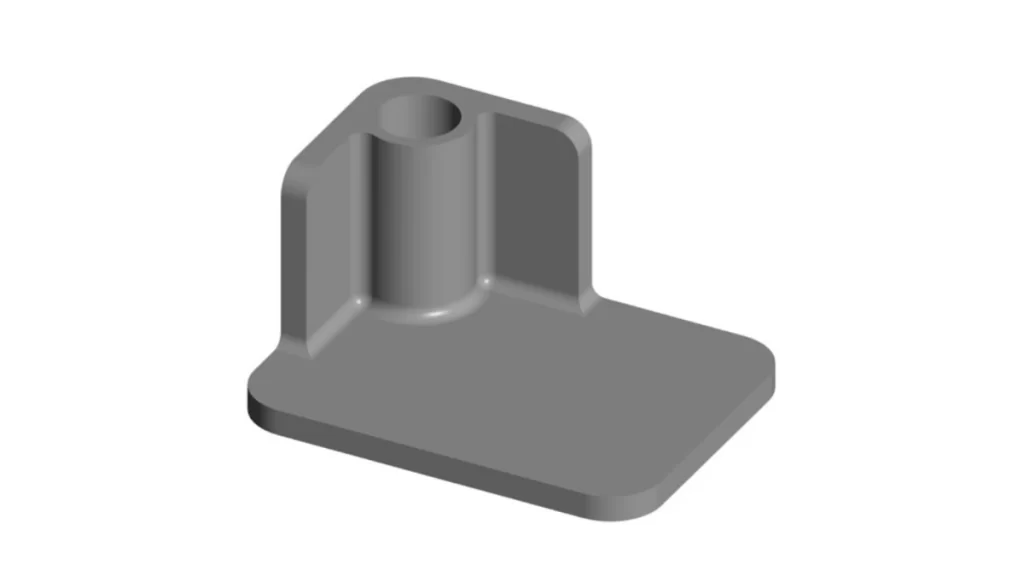
Ribs and Bosses Placements In Molded Enclosure
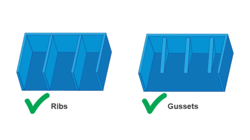
You can use internal ribs to improve the strength of your injection molded enclosures
without much material. These thin vertical structures increase rigidity. Therefore, it reduces part deformation under stress.
Install these features on large flat surfaces or next to mounting points to avoid flexing. Maintain the rib thickness at 50–75% of the adjacent wall and always use a small radius at the bottom of the rib to prevent stress concentration.
Bosses and other features that will bear load, especially those used with screws or fasteners, should be reinforced with ribs to ensure strength and minimize sink marks. These features can be implemented by adding them, helping to minimise sink marks and better distribute the load across the enclosure.
Round Corners to Prevent Failures
Round Corners In Enclosure Design
Sharp corners give a modern look to things. However, they will create weak points. Such areas are subject to stress concentration and may develop cracking with time. Rounded corners also spread stress more evenly and increase material flow during moulding. They also minimize the chance of cosmetic problems and short shots in production.
Therefore, large radii should be used on the internal and external edges. Strength and molten plastic will flow more smoothly, thus achieving the complete and uniform fill.
Addressing Mold Design Constraints
Designing a mold-friendly part is pivotal to cost and consistency. If your enclosure has undercuts or vertical walls without draft, you are likely to cause damage to the mold or create non-ejectable parts. So, you must be smart regarding the parting lines, draft angles, and undercut relief from the start.
Minimizing or Eliminating Undercuts
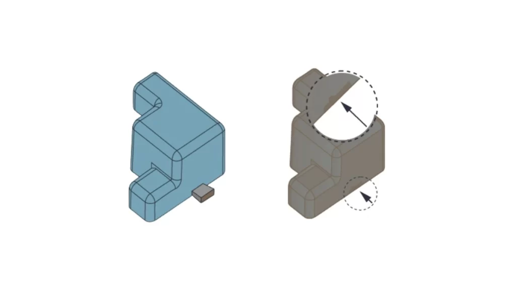
Simplifying Undercuts In Injection Molding
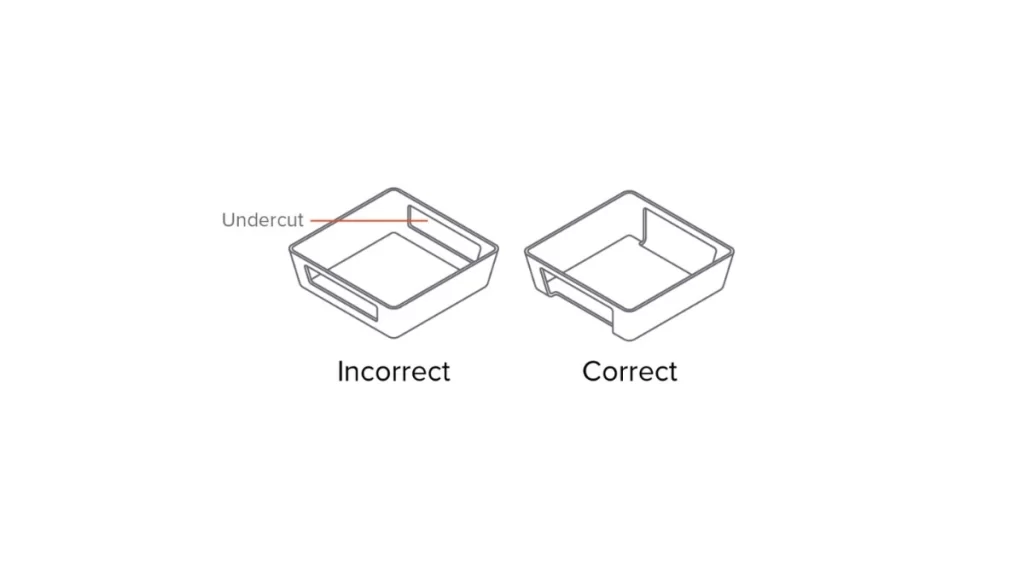
Undercuts are forms that prevent straight ejection from the mold. These are internal clips, side holes, or snap fits. Although undercuts can’t always be avoided, you should design them with collapsible cores or sliders in mind. This incurs tooling costs, so avoid undercuts as much as possible or substitute them with alternative fastening procedures.
At Prolean Tech, we look at your enclosure for undercut risk at the early stages of development. In that way, our team assists you in redesigning the feature with low-cost tooling strategies.
Proper Draft Angle Application
Draft Angles For Injection Molded Enclosure
The draft is the small taper on the vertical wall to eject it from the mold easily. Your piece may get damaged and stuck in the mold with no draft. Plastic enclosures generally perform well with a 3° to 5° draft angle, depending on the part’s geometry and the material used. Apply to all walls, bosses, ribs, and gussets.
Moreover, the draft improves surface finish and reduces the need for high ejection force to a greater degree. The larger the surface slants upwards, the more urgent it is to add a draft.
Try Prolean Now!
Parting Line Placement
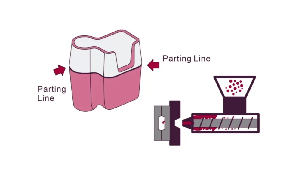
Parting Line In Injection Molding
The parting line is where the mold splits down the line to release the part. This line has to be carefully located to avoid flash, misalignment, and cosmetic issues. It is best at the edge of sharp or symmetric features. Don’t use parting lines on large visible areas, especially if your product has to be highly polished.
Make sure your CAD model describes this line so that the tool makers can design with confidence. Complexity and cost of tooling grow if a parting line affects a filleted surface.
External Factors and Performance Requirements
Plastic enclosures are not developed in silos. They need to perform in real-world circumstances. Is the enclosure for outdoor use? Will it be exposed to vibration, heat, or chemicals? All of these situations require special materials and design choices.
For example, electrical housing insulation is required. Outdoor enclosures may require UV-stable resins/gaskets for water seal. Define your performance requirements early. How you do it, your material and wall thickness selection, and ways of enhancing your walls align with end-use conditions.
Simulation and Testing Are Essential
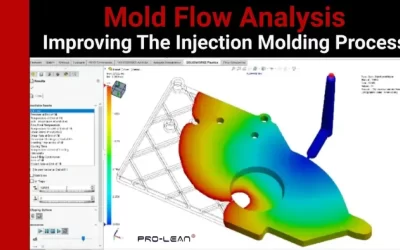
Before you commence mass-scale production, you must evaluate your design via simulation or testing. Regarding injection molding quality control, Finite element analysis (FEA) can help you predict weak points of your enclosure according to stress, vibration, and heat loads. Prototypes can verify fit, form, and assembly function. This will facilitate your design before cutting tooling, saving time and money.
FEA is particularly important in the vicinity of ribbed areas, mounting bosses, and the snap-fit regions. If your design is subject to repetitive stress, you can optimize it by increasing thickness and changing geometry before tooling.
Final Verdict
Overall, you have to understand that product design directly influences manufacturing cost. It isn’t just that an enclosure should be aesthetically pleasing; it must also be manufacturable, functional, and affordably produced. When you practice smart design, you make fewer errors, speed up the tooling, and deliver products better.
Injection molding continues to be the choice of custom plastic electronic enclosures. It provides high efficiency of cycle times, repeatability, and excellent scalability. Success starts with designs that adhere to DFM best practices – features that shape cleanly, fit well, and persist consistently.
At Prolean Tech, we offer in-class injection molding service. We work with you to design better enclosures from day one. Our team gives expert DFM feedback, accurate tooling, and a rapid production turnaround. Once you are ready to custom shape plastic enclosures, we are prepared to help.
Leave manufacturing to Prolean Tech – and get back to engineering. Sign up, upload your designs, and get a quote now. We’ll make your enclosure ideas live with speed, quality, and confidence.
FAQ’s
Q1. What plastic is used for electronic housing?
ABS and polycarbonate are commonly used injection molding materials for electronic housings. ABS is lightweight and strong, making it ideal for most devices. Polycarbonate is selected when more toughness or flame resistance is required. The final choice depends on the strength, heat resistance, and flexibility your product needs.
Q2. How much does it cost to injection mold plastic?
Plastic injection molding cost varies based on the mold and part design. A simple mold can start at around $3,000, while complex ones can go much higher.

0 Comments